CAM Take Photo and Save to MicroSD Card
Learn how to take photos with the ESP32-CAM board and save them to a microSD card using Arduino IDE. When you press the ESP32-CAM RESET button, it wakes up, takes a photo and saves it in the microSD card.
![]() We'll be using the ESP32-CAM board labelled as AI-Thinker module, but other modules should also work by making the correct pin assignment in the code.
The ESP32-CAM board is a $9 device (or less) that combines an ESP32-S chip, an OV2640 camera, a microSD card slot and several GPIO pins.
We'll be using the ESP32-CAM board labelled as AI-Thinker module, but other modules should also work by making the correct pin assignment in the code.
The ESP32-CAM board is a $9 device (or less) that combines an ESP32-S chip, an OV2640 camera, a microSD card slot and several GPIO pins.
![]() For an introduction to the ESP32-CAM, you can follow the next tutorials:
ESP32-CAM Video Streaming and Face Recognition with Arduino IDE
ESP32-CAM Video Streaming Web Server (works with Home Assistant, Node-RED, etc)
ESP32-CAM Troubleshooting Guide
For an introduction to the ESP32-CAM, you can follow the next tutorials:
ESP32-CAM Video Streaming and Face Recognition with Arduino IDE
ESP32-CAM Video Streaming Web Server (works with Home Assistant, Node-RED, etc)
ESP32-CAM Troubleshooting Guide
Watch the Video Tutorial
To learn how to take photos with the ESP32-CAM and save them in the microSD card, you can watch the following video tutorial or keep reading this page for the written instructions and all the resources.
Parts Required
To follow this tutorial you need the following components:
ESP32-CAM with OV2640 read Best ESP32-CAM Dev Boards
MicroSD card
FTDI programmer
Female-to-female jumper wires
5V power supply for ESP32-CAM or power bank (optional)
You can use the preceding links or go directly to MakerAdvisor.com/tools to find all the parts for your projects at the best price!
![]()
Project Overview
Here is a quick overview on how the project works.
![]() The ESP32-CAM is in deep sleep mode
Press the RESET button to wake up the board
The camera takes a photo
The photo is saved in the microSD card with the name: pictureX.jpg, where X corresponds to the picture number
The picture number will be saved in the ESP32 flash memory so that it is not erased during RESET and we can keep track of the number of photos taken.
The ESP32-CAM is in deep sleep mode
Press the RESET button to wake up the board
The camera takes a photo
The photo is saved in the microSD card with the name: pictureX.jpg, where X corresponds to the picture number
The picture number will be saved in the ESP32 flash memory so that it is not erased during RESET and we can keep track of the number of photos taken.
Formatting MicroSD Card
The first thing we recommend doing is formatting your microSD card. You can use the Windows formatter tool or any other microSD formatter software.
1. Insert the microSD card in your computer. Go to My Computer and right click in the SD card. Select Format as shown in figure below.
![Formatting your microSD card Windows]() 2. A new window pops up. Select FAT32, press Start to initialize the formatting process and follow the onscreen instructions.
2. A new window pops up. Select FAT32, press Start to initialize the formatting process and follow the onscreen instructions.
![Formatting your microSD card Windows]() Note: according to the product specifications, the ESP32-CAM should only support 4 GB SD cards. However, we've tested with 16 GB SD card and it works well.
Note: according to the product specifications, the ESP32-CAM should only support 4 GB SD cards. However, we've tested with 16 GB SD card and it works well.
Installing the ESP32 add-on
We'll program the ESP32 board using Arduino IDE. So you need the Arduino IDE installed as well as the ESP32 add-on. You can follow one of the next tutorials to install the ESP32 add-on, if you haven't already:
Installing the ESP32 Board in Arduino IDE (Windows instructions)
Installing the ESP32 Board in Arduino IDE (Mac and Linux instructions)
Take and Save Photo Sketch
Copy the following code to your Arduino IDE.
/*********
Rui Santos
Complete project details at https://RandomNerdTutorials.com/esp32-cam-take-photo-save-microsd-card
IMPORTANT!!!
- Select Board "AI Thinker ESP32-CAM"
- GPIO 0 must be connected to GND to upload a sketch
- After connecting GPIO 0 to GND, press the ESP32-CAM on-board RESET button to put your board in flashing mode
Permission is hereby granted, free of charge, to any person obtaining a copy
of this software and associated documentation files.
The above copyright notice and this permission notice shall be included in all
copies or substantial portions of the Software.
*********/
#include "esp_camera.h"
#include "Arduino.h"
#include "FS.h" // SD Card ESP32
#include "SD_MMC.h" // SD Card ESP32
#include "soc/soc.h" // Disable brownour problems
#include "soc/rtc_cntl_reg.h" // Disable brownour problems
#include "driver/rtc_io.h"
#include <EEPROM.h> // read and write from flash memory
// define the number of bytes you want to access
#define EEPROM_SIZE 1
// Pin definition for CAMERA_MODEL_AI_THINKER
#define PWDN_GPIO_NUM 32
#define RESET_GPIO_NUM -1
#define XCLK_GPIO_NUM 0
#define SIOD_GPIO_NUM 26
#define SIOC_GPIO_NUM 27
#define Y9_GPIO_NUM 35
#define Y8_GPIO_NUM 34
#define Y7_GPIO_NUM 39
#define Y6_GPIO_NUM 36
#define Y5_GPIO_NUM 21
#define Y4_GPIO_NUM 19
#define Y3_GPIO_NUM 18
#define Y2_GPIO_NUM 5
#define VSYNC_GPIO_NUM 25
#define HREF_GPIO_NUM 23
#define PCLK_GPIO_NUM 22
int pictureNumber = 0;
void setup() {
WRITE_PERI_REG(RTC_CNTL_BROWN_OUT_REG, 0); //disable brownout detector
Serial.begin(115200);
//Serial.setDebugOutput(true);
//Serial.println();
camera_config_t config;
config.ledc_channel = LEDC_CHANNEL_0;
config.ledc_timer = LEDC_TIMER_0;
config.pin_d0 = Y2_GPIO_NUM;
config.pin_d1 = Y3_GPIO_NUM;
config.pin_d2 = Y4_GPIO_NUM;
config.pin_d3 = Y5_GPIO_NUM;
config.pin_d4 = Y6_GPIO_NUM;
config.pin_d5 = Y7_GPIO_NUM;
config.pin_d6 = Y8_GPIO_NUM;
config.pin_d7 = Y9_GPIO_NUM;
config.pin_xclk = XCLK_GPIO_NUM;
config.pin_pclk = PCLK_GPIO_NUM;
config.pin_vsync = VSYNC_GPIO_NUM;
config.pin_href = HREF_GPIO_NUM;
config.pin_sscb_sda = SIOD_GPIO_NUM;
config.pin_sscb_scl = SIOC_GPIO_NUM;
config.pin_pwdn = PWDN_GPIO_NUM;
config.pin_reset = RESET_GPIO_NUM;
config.xclk_freq_hz = 20000000;
config.pixel_format = PIXFORMAT_JPEG;
if(psramFound()){
config.frame_size = FRAMESIZE_UXGA; // FRAMESIZE_ + QVGA|CIF|VGA|SVGA|XGA|SXGA|UXGA
config.jpeg_quality = 10;
config.fb_count = 2;
} else {
config.frame_size = FRAMESIZE_SVGA;
config.jpeg_quality = 12;
config.fb_count = 1;
}
// Init Camera
esp_err_t err = esp_camera_init(&config);
if (err != ESP_OK) {
Serial.printf("Camera init failed with error 0x%x", err);
return;
}
//Serial.println("Starting SD Card");
if(!SD_MMC.begin()){
Serial.println("SD Card Mount Failed");
return;
}
uint8_t cardType = SD_MMC.cardType();
if(cardType == CARD_NONE){
Serial.println("No SD Card attached");
return;
}
camera_fb_t * fb = NULL;
// Take Picture with Camera
fb = esp_camera_fb_get();
if(!fb) {
Serial.println("Camera capture failed");
return;
}
// initialize EEPROM with predefined size
EEPROM.begin(EEPROM_SIZE);
pictureNumber = EEPROM.read(0) + 1;
// Path where new picture will be saved in SD Card
String path = "/picture" + String(pictureNumber) +".jpg";
fs::FS &fs = SD_MMC;
Serial.printf("Picture file name: %s\n", path.c_str());
File file = fs.open(path.c_str(), FILE_WRITE);
if(!file){
Serial.println("Failed to open file in writing mode");
}
else {
file.write(fb->buf, fb->len); // payload (image), payload length
Serial.printf("Saved file to path: %s\n", path.c_str());
EEPROM.write(0, pictureNumber);
EEPROM.commit();
}
file.close();
esp_camera_fb_return(fb);
// Turns off the ESP32-CAM white on-board LED (flash) connected to GPIO 4
pinMode(4, OUTPUT);
digitalWrite(4, LOW);
rtc_gpio_hold_en(GPIO_NUM_4);
delay(2000);
Serial.println("Going to sleep now");
delay(2000);
esp_deep_sleep_start();
Serial.println("This will never be printed");
}
void loop() {
}
View raw code
The code starts by including the necessary libraries to use the camera. We also include the libraries needed to interact with the microSD card:
#include "esp_camera.h"
#include "Arduino.h"
#include "FS.h" // SD Card ESP32
#include "SD_MMC.h" // SD Card ESP32
#include "soc/soc.h" // Disable brownour problems
#include "soc/rtc_cntl_reg.h" // Disable brownour problems
#include "driver/rtc_io.h"
#include <EEPROM.h> // read and write from flash memory
And the EEPROM library to save permanent data in the flash memory.
#include <EEPROM.h>
CAM Video Streaming Web Server (works with Home Assistant)
In this project we're going to build an IP surveillance camera with the ESP32-CAM board. The ESP32 camera is going to host a video streaming web server that you can access with any device in your network.
![]() You can integrate this video streaming web server with popular home automation platforms like Home Assistant or Node-RED. In this tutorial, we'll show you how to integrate it with Home Assistant and Node-RED.
You can integrate this video streaming web server with popular home automation platforms like Home Assistant or Node-RED. In this tutorial, we'll show you how to integrate it with Home Assistant and Node-RED.
Watch the Video Tutorial
You can watch the video tutorial or keep reading this page for the written instructions.
Parts Required
To follow this tutorial you need the following components:
ESP32-CAM with OV2640 read Best ESP32-CAM Dev Boards
FTDI programmer
Female-to-female jumper wires
Fake/dummy dome security camera
5V power supply for ESP32-CAM
Optional Home Assistant on Raspberry Pi:
Raspberry Pi Board read Best Raspberry Pi Starter Kits
MicroSD Card 32GB Class10
Raspberry Pi Power Supply (5V 2.5A)
You can use the preceding links or go directly to MakerAdvisor.com/tools to find all the parts for your projects at the best price!
![]()
Introducing the ESP32-CAM
The ESP32-CAM is a very small camera module with the ESP32-S chip that costs less than $10. You can read our getting started guide for the ESP32-CAM and learn how to use the Video Streaming and Face Recognition example.
![]()
Video Streaming Server
Follow the next steps to build a video streaming web server with the ESP32-CAM that you can access on your local network.
1. Install the ESP32 add-on
In this example, we use Arduino IDE to program the ESP32-CAM board. So, you need to have Arduino IDE installed as well as the ESP32 add-on. Follow one of the next tutorials to install the ESP32 add-on, if you haven't already:
Installing the ESP32 Board in Arduino IDE (Windows instructions)
Installing the ESP32 Board in Arduino IDE (Mac and Linux instructions)
2. Video Streaming Web Server Code
After that, copy the code below to your Arduino IDE.
/*********
Rui Santos
Complete project details at https://RandomNerdTutorials.com/esp32-cam-video-streaming-web-server-camera-home-assistant/
IMPORTANT!!!
- Select Board "AI Thinker ESP32-CAM"
- GPIO 0 must be connected to GND to upload a sketch
- After connecting GPIO 0 to GND, press the ESP32-CAM on-board RESET button to put your board in flashing mode
Permission is hereby granted, free of charge, to any person obtaining a copy
of this software and associated documentation files.
The above copyright notice and this permission notice shall be included in all
copies or substantial portions of the Software.
*********/
#include "esp_camera.h"
#include <WiFi.h>
#include "esp_timer.h"
#include "img_converters.h"
#include "Arduino.h"
#include "fb_gfx.h"
#include "soc/soc.h" //disable brownout problems
#include "soc/rtc_cntl_reg.h" //disable brownout problems
#include "esp_http_server.h"
//Replace with your network credentials
const char* ssid = "REPLACE_WITH_YOUR_SSID";
const char* password = "REPLACE_WITH_YOUR_PASSWORD";
#define PART_BOUNDARY "123456789000000000000987654321"
// This project was tested with the AI Thinker Model, M5STACK PSRAM Model and M5STACK WITHOUT PSRAM
#define CAMERA_MODEL_AI_THINKER
//#define CAMERA_MODEL_M5STACK_PSRAM
//#define CAMERA_MODEL_M5STACK_WITHOUT_PSRAM
// Not tested with this model
//#define CAMERA_MODEL_WROVER_KIT
#if defined(CAMERA_MODEL_WROVER_KIT)
#define PWDN_GPIO_NUM -1
#define RESET_GPIO_NUM -1
#define XCLK_GPIO_NUM 21
#define SIOD_GPIO_NUM 26
#define SIOC_GPIO_NUM 27
#define Y9_GPIO_NUM 35
#define Y8_GPIO_NUM 34
#define Y7_GPIO_NUM 39
#define Y6_GPIO_NUM 36
#define Y5_GPIO_NUM 19
#define Y4_GPIO_NUM 18
#define Y3_GPIO_NUM 5
#define Y2_GPIO_NUM 4
#define VSYNC_GPIO_NUM 25
#define HREF_GPIO_NUM 23
#define PCLK_GPIO_NUM 22
#elif defined(CAMERA_MODEL_M5STACK_PSRAM)
#define PWDN_GPIO_NUM -1
#define RESET_GPIO_NUM 15
#define XCLK_GPIO_NUM 27
#define SIOD_GPIO_NUM 25
#define SIOC_GPIO_NUM 23
#define Y9_GPIO_NUM 19
#define Y8_GPIO_NUM 36
#define Y7_GPIO_NUM 18
#define Y6_GPIO_NUM 39
#define Y5_GPIO_NUM 5
#define Y4_GPIO_NUM 34
#define Y3_GPIO_NUM 35
#define Y2_GPIO_NUM 32
#define VSYNC_GPIO_NUM 22
#define HREF_GPIO_NUM 26
#define PCLK_GPIO_NUM 21
#elif defined(CAMERA_MODEL_M5STACK_WITHOUT_PSRAM)
#define PWDN_GPIO_NUM -1
#define RESET_GPIO_NUM 15
#define XCLK_GPIO_NUM 27
#define SIOD_GPIO_NUM 25
#define SIOC_GPIO_NUM 23
#define Y9_GPIO_NUM 19
#define Y8_GPIO_NUM 36
#define Y7_GPIO_NUM 18
#define Y6_GPIO_NUM 39
#define Y5_GPIO_NUM 5
#define Y4_GPIO_NUM 34
#define Y3_GPIO_NUM 35
#define Y2_GPIO_NUM 17
#define VSYNC_GPIO_NUM 22
#define HREF_GPIO_NUM 26
#define PCLK_GPIO_NUM 21
#elif defined(CAMERA_MODEL_AI_THINKER)
#define PWDN_GPIO_NUM 32
#define RESET_GPIO_NUM -1
#define XCLK_GPIO_NUM 0
#define SIOD_GPIO_NUM 26
#define SIOC_GPIO_NUM 27
#define Y9_GPIO_NUM 35
#define Y8_GPIO_NUM 34
#define Y7_GPIO_NUM 39
#define Y6_GPIO_NUM 36
#define Y5_GPIO_NUM 21
#define Y4_GPIO_NUM 19
#define Y3_GPIO_NUM 18
#define Y2_GPIO_NUM 5
#define VSYNC_GPIO_NUM 25
#define HREF_GPIO_NUM 23
#define PCLK_GPIO_NUM 22
#else
#error "Camera model not selected"
#endif
static const char* _STREAM_CONTENT_TYPE = "multipart/x-mixed-replace;boundary=" PART_BOUNDARY;
static const char* _STREAM_BOUNDARY = "\r\n--" PART_BOUNDARY "\r\n";
static const char* _STREAM_PART = "Content-Type: image/jpeg\r\nContent-Length: %u\r\n\r\n";
httpd_handle_t stream_httpd = NULL;
static esp_err_t stream_handler(httpd_req_t *req){
camera_fb_t * fb = NULL;
esp_err_t res = ESP_OK;
size_t _jpg_buf_len = 0;
uint8_t * _jpg_buf = NULL;
char * part_buf[64];
res = httpd_resp_set_type(req, _STREAM_CONTENT_TYPE);
if(res != ESP_OK){
return res;
}
while(true){
fb = esp_camera_fb_get();
if (!fb) {
Serial.println("Camera capture failed");
res = ESP_FAIL;
} else {
if(fb->width > 400){
if(fb->format != PIXFORMAT_JPEG){
bool jpeg_converted = frame2jpg(fb, 80, &_jpg_buf, &_jpg_buf_len);
esp_camera_fb_return(fb);
fb = NULL;
if(!jpeg_converted){
Serial.println("JPEG compression failed");
res = ESP_FAIL;
}
} else {
_jpg_buf_len = fb->len;
_jpg_buf = fb->buf;
}
}
}
if(res == ESP_OK){
size_t hlen = snprintf((char *)part_buf, 64, _STREAM_PART, _jpg_buf_len);
res = httpd_resp_send_chunk(req, (const char *)part_buf, hlen);
}
if(res == ESP_OK){
res = httpd_resp_send_chunk(req, (const char *)_jpg_buf, _jpg_buf_len);
}
if(res == ESP_OK){
res = httpd_resp_send_chunk(req, _STREAM_BOUNDARY, strlen(_STREAM_BOUNDARY));
}
if(fb){
esp_camera_fb_return(fb);
fb = NULL;
_jpg_buf = NULL;
} else if(_jpg_buf){
free(_jpg_buf);
_jpg_buf = NULL;
}
if(res != ESP_OK){
break;
}
//Serial.printf("MJPG: %uB\n",(uint32_t)(_jpg_buf_len));
}
return res;
}
void startCameraServer(){
httpd_config_t config = HTTPD_DEFAULT_CONFIG();
config.server_port = 80;
httpd_uri_t index_uri = {
.uri = "/",
.method = HTTP_GET,
.handler = stream_handler,
.user_ctx = NULL
};
//Serial.printf("Starting web server on port: '%d'\n", config.server_port);
if (httpd_start(&stream_httpd, &config) == ESP_OK) {
httpd_register_uri_handler(stream_httpd, &index_uri);
}
}
void setup() {
WRITE_PERI_REG(RTC_CNTL_BROWN_OUT_REG, 0); //disable brownout detector
Serial.begin(115200);
Serial.setDebugOutput(false);
camera_config_t config;
config.ledc_channel = LEDC_CHANNEL_0;
config.ledc_timer = LEDC_TIMER_0;
config.pin_d0 = Y2_GPIO_NUM;
config.pin_d1 = Y3_GPIO_NUM;
config.pin_d2 = Y4_GPIO_NUM;
config.pin_d3 = Y5_GPIO_NUM;
config.pin_d4 = Y6_GPIO_NUM;
config.pin_d5 = Y7_GPIO_NUM;
config.pin_d6 = Y8_GPIO_NUM;
config.pin_d7 = Y9_GPIO_NUM;
config.pin_xclk = XCLK_GPIO_NUM;
config.pin_pclk = PCLK_GPIO_NUM;
config.pin_vsync = VSYNC_GPIO_NUM;
config.pin_href = HREF_GPIO_NUM;
config.pin_sscb_sda = SIOD_GPIO_NUM;
config.pin_sscb_scl = SIOC_GPIO_NUM;
config.pin_pwdn = PWDN_GPIO_NUM;
config.pin_reset = RESET_GPIO_NUM;
config.xclk_freq_hz = 20000000;
config.pixel_format = PIXFORMAT_JPEG;
if(psramFound()){
config.frame_size = FRAMESIZE_UXGA;
config.jpeg_quality = 10;
config.fb_count = 2;
} else {
config.frame_size = FRAMESIZE_SVGA;
config.jpeg_quality = 12;
config.fb_count = 1;
}
// Camera init
esp_err_t err = esp_camera_init(&config);
if (err != ESP_OK) {
Serial.printf("Camera init failed with error 0x%x", err);
return;
}
// Wi-Fi connection
WiFi.begin(ssid, password);
while (WiFi.status() != WL_CONNECTED) {
delay(500);
Serial.print(".");
}
Serial.println("");
Serial.println("WiFi connected");
Serial.print("Camera Stream Ready! Go to: http://");
Serial.print(WiFi.localIP());
// Start streaming web server
startCameraServer();
}
void loop() {
delay(1);
}
View raw code
Before uploading the code, you need to insert your network credentials in the following variables:
const char* ssid = "REPLACE_WITH_YOUR_SSID";
const char* password = "REPLACE_WITH_YOUR_PASSWORD";
Then, make sure you select the right camera module. In this case, we're using the AI-THINKER Model.
![]() If you're using the same camera module, you don't need to change anything on the code.
#define CAMERA_MODEL_AI_THINKER
Now, you can upload the code to your ESP32-CAM board.
If you're using the same camera module, you don't need to change anything on the code.
#define CAMERA_MODEL_AI_THINKER
Now, you can upload the code to your ESP32-CAM board.
3. Uploading the Code
Connect the ESP32-CAM board to your computer using an FTDI programmer. Follow the next schematic diagram:
![]() Many FTDI programmers have a jumper that allows you to select 3.3V or 5V. Make sure the jumper is in the right place to select 5V.
Important: GPIO 0 needs to be connected to GND so that you're able to upload code.
Many FTDI programmers have a jumper that allows you to select 3.3V or 5V. Make sure the jumper is in the right place to select 5V.
Important: GPIO 0 needs to be connected to GND so that you're able to upload code.
| ESP32-CAM |
FTDI Programmer |
| GND |
GND |
| 5V |
VCC (5V) |
| U0R |
TX |
| U0T |
RX |
| GPIO 0 |
GND |
To upload the code, follow the next steps:
1) Go to Tools > Board and select AI-Thinker ESP32-CAM.
2) Go to Tools > Port and select the COM port the ESP32 is connected to.
3) Then, click the upload button to upload the code.
![]() 4) When you start to see these dots on the debugging window as shown below, press the ESP32-CAM on-board RST button.
4) When you start to see these dots on the debugging window as shown below, press the ESP32-CAM on-board RST button.
![]() After a few seconds, the code should be successfully uploaded to your board.
After a few seconds, the code should be successfully uploaded to your board.
Getting the IP address
After uploading the code, disconnect GPIO 0 from GND. Open the Serial Monitor at a baud rate of 115200. Press the ESP32-CAM on-board Reset button.
The ESP32 IP address should be printed in the Serial Monitor.
![]()
Accessing the Video Streaming Server
Now, you can access your camera streaming server on your local network. Open a browser and type the ESP32-CAM IP address. A page with the current video streaming should load.
![]()
Home Assistant Integration
![]() Having just the ESP32-CAM working via IP might be useful for most people, but you can integrate this project with Home Assistant (or with other home automation platforms). Continue reading to learn how to integrate with Home Assistant.
Having just the ESP32-CAM working via IP might be useful for most people, but you can integrate this project with Home Assistant (or with other home automation platforms). Continue reading to learn how to integrate with Home Assistant.
Prerequisites
You should be familiar with the Raspberry Pi read Getting Started with Raspberry Pi.
Getting Started with Home Assistant on Raspberry Pi
Adding ESP32-CAM to Home Assistant
Open your Home Assistant dashboard and go to the more Settings menu.
![]() Open Configure UI:
Open Configure UI:
![]() Add a new card to your Dashboard:
Add a new card to your Dashboard:
![]() Pick a card of the type Picture.
Pick a card of the type Picture.
![]() In the Image URL field, enter your ESP32-CAM IP address. Then, click the SAVE button and return to the main dashboard.
In the Image URL field, enter your ESP32-CAM IP address. Then, click the SAVE button and return to the main dashboard.
![]() If you're using the configuration file, this is what you need to add.
If you're using the configuration file, this is what you need to add.
![]() After that, Home Assistant can display the ESP32-CAM video streaming.
After that, Home Assistant can display the ESP32-CAM video streaming.
![]()
Taking It Further
To take this project further, you can use one fake dummy camera and place the ESP32-CAM inside.
![]() The ESP32-CAM board fits perfectly into the dummy camera enclosure.
The ESP32-CAM board fits perfectly into the dummy camera enclosure.
![]() You can power it using a 5V power adapter through the ESP32-CAM GND and 5V pins.
You can power it using a 5V power adapter through the ESP32-CAM GND and 5V pins.
![]() Place the surveillance camera in a suitable place.
Place the surveillance camera in a suitable place.
![]() After that, go to the camera IP address or to your Home Assistant dashboard and see in real time what's happening. The following image shows us testing the video streaming camera. Sara is taking a screenshot while I'm filming the camera.
After that, go to the camera IP address or to your Home Assistant dashboard and see in real time what's happening. The following image shows us testing the video streaming camera. Sara is taking a screenshot while I'm filming the camera.
![]() It's impressive what this little $9 ESP32 camera module can do and it's been working reliably. Now, we can use the surveillance camera to see in real time what's happening in my front entrance.
It's impressive what this little $9 ESP32 camera module can do and it's been working reliably. Now, we can use the surveillance camera to see in real time what's happening in my front entrance.
![]()
Tip: Node-RED Integration
The video streaming web server also integrates with Node-RED and Node-RED Dashboard. You just need to create a Template node and add the following:
<div style="margin-bottom: 10px;">
<img src="https://YOUR-ESP32-CAM-IP-ADDRESS" width="650px">
</div>
In the src attribute, you need to type your ESP32-CAM IP address:
<div style="margin-bottom: 10px;">
<img src="https://192.168.1.91" width="650px">
</div>
Troubleshooting
If you're getting any of the following errors, read our ESP32-CAM Troubleshooting Guide: Most Common Problems Fixed
Failed to connect to ESP32: Timed out waiting for packet header
Camera init failed with error 0x20001 or similar
Brownout detector or Guru meditation error
Sketch too big error Wrong partition scheme selected
Board at COMX is not available COM Port Not Selected
Psram error: GPIO isr service is not installed
Weak Wi-Fi Signal
No IP Address in Arduino IDE Serial Monitor
Can't open web server
The image lags/shows lots of latency
![]()
Wrapping Up
In this tutorial we've shown you how to build a simple video streaming web server with the ESP32-CAM board to build an IP camera. The web server we've built can be easily integrated with your home automation platform like Node-RED or Home Assistant.
We hope you've find this tutorial useful. If you don't have an ESP32-CAM yet, you can grab it here.
CAM PIR Motion Detector with Photo Capture (saves to microSD card)
In this project, we're going to make a motion sensor detector with photo capture using an ESP32-CAM. When your PIR sensor detects motion, it wakes up, takes a photo and saves it in the microSD card.
![]() This project is very similar with a previous one, but after so many requests, we added a PIR motion sensor to the circuit. So, when motion is detected a picture is taken and saved on the microSD card.
Other ESP32-CAM projects and tutorials:
ESP32-CAM Video Streaming and Face Recognition with Arduino IDE
ESP32-CAM Video Streaming Web Server (Home Assistant, Node-RED, etc)
ESP32-CAM Take Photo and Save to MicroSD Card
Take Photo, Save to SPIFFS and Display in Web Server
ESP32-CAM Troubleshooting Guide
We have a similar project using a Raspberry Pi and a camera module:
Raspberry Pi Motion Detector with Photo Capture
This project is very similar with a previous one, but after so many requests, we added a PIR motion sensor to the circuit. So, when motion is detected a picture is taken and saved on the microSD card.
Other ESP32-CAM projects and tutorials:
ESP32-CAM Video Streaming and Face Recognition with Arduino IDE
ESP32-CAM Video Streaming Web Server (Home Assistant, Node-RED, etc)
ESP32-CAM Take Photo and Save to MicroSD Card
Take Photo, Save to SPIFFS and Display in Web Server
ESP32-CAM Troubleshooting Guide
We have a similar project using a Raspberry Pi and a camera module:
Raspberry Pi Motion Detector with Photo Capture
Watch the Video Tutorial
You can watch the video tutorial or continue reading for the complete project instructions.
Parts Required
For this project, you'll need the following parts:
ESP32-CAM with OV2640 read Best ESP32-CAM Dev Boards
MicroSD card
PIR motion sensor
2N3904 transistor
FTDI programmer
Female-to-female jumper wires
5V power supply for ESP32-CAM or power bank (optional)
You can use the preceding links or go directly to MakerAdvisor.com/tools to find all the parts for your projects at the best price!
![]()
Project Overview
![]() Here is a quick overview on how the project works.
The ESP32-CAM is in deep sleep mode with external wake up enabled.
When motion is detected, the PIR motion sensor sends a signal to wake up the ESP32.
The ESP32-CAM takes a photo and saves it on the microSD card.
It goes back to deep sleep mode until a new signal from the PIR motion sensor is received.
Recommended reading: ESP32 Deep Sleep with Arduino IDE and Wake Up Sources
Here is a quick overview on how the project works.
The ESP32-CAM is in deep sleep mode with external wake up enabled.
When motion is detected, the PIR motion sensor sends a signal to wake up the ESP32.
The ESP32-CAM takes a photo and saves it on the microSD card.
It goes back to deep sleep mode until a new signal from the PIR motion sensor is received.
Recommended reading: ESP32 Deep Sleep with Arduino IDE and Wake Up Sources
Formatting MicroSD Card
The first thing we recommend doing is formatting your microSD card. You can use the Windows formatter tool or any other microSD formatter software.
1. Insert the microSD card in your computer. Go to My Computer and right click in the SD card. Select Format as shown in figure below.
![Formatting your microSD card Windows]() 2. A new window pops up. Select FAT32, press Start to initialize the formatting process and follow the onscreen instructions.
2. A new window pops up. Select FAT32, press Start to initialize the formatting process and follow the onscreen instructions.
![Formatting your microSD card Windows]() Note: according to the product specifications, the ESP32-CAM should only support 4 GB SD cards. However, we've tested with 16 GB SD card and it works well.
Note: according to the product specifications, the ESP32-CAM should only support 4 GB SD cards. However, we've tested with 16 GB SD card and it works well.
Installing the ESP32 add-on
We'll program the ESP32 board using Arduino IDE. So, you need the Arduino IDE installed as well as the ESP32 add-on:
Installing the ESP32 Board in Arduino IDE (Windows, Mac OS X, Linux)
ESP32-CAM Take Photo with PIR Sketch
Copy the following code to your Arduino IDE.
/*********
Rui Santos
Complete project details at https://RandomNerdTutorials.com/esp32-cam-pir-motion-detector-photo-capture/
IMPORTANT!!!
- Select Board "AI Thinker ESP32-CAM"
- GPIO 0 must be connected to GND to upload a sketch
- After connecting GPIO 0 to GND, press the ESP32-CAM on-board RESET button to put your board in flashing mode
Permission is hereby granted, free of charge, to any person obtaining a copy
of this software and associated documentation files.
The above copyright notice and this permission notice shall be included in all
copies or substantial portions of the Software.
*********/
#include "esp_camera.h"
#include "Arduino.h"
#include "FS.h" // SD Card ESP32
#include "SD_MMC.h" // SD Card ESP32
#include "soc/soc.h" // Disable brownour problems
#include "soc/rtc_cntl_reg.h" // Disable brownour problems
#include "driver/rtc_io.h"
#include <EEPROM.h> // read and write from flash memory
// define the number of bytes you want to access
#define EEPROM_SIZE 1
RTC_DATA_ATTR int bootCount = 0;
// Pin definition for CAMERA_MODEL_AI_THINKER
#define PWDN_GPIO_NUM 32
#define RESET_GPIO_NUM -1
#define XCLK_GPIO_NUM 0
#define SIOD_GPIO_NUM 26
#define SIOC_GPIO_NUM 27
#define Y9_GPIO_NUM 35
#define Y8_GPIO_NUM 34
#define Y7_GPIO_NUM 39
#define Y6_GPIO_NUM 36
#define Y5_GPIO_NUM 21
#define Y4_GPIO_NUM 19
#define Y3_GPIO_NUM 18
#define Y2_GPIO_NUM 5
#define VSYNC_GPIO_NUM 25
#define HREF_GPIO_NUM 23
#define PCLK_GPIO_NUM 22
int pictureNumber = 0;
void setup() {
WRITE_PERI_REG(RTC_CNTL_BROWN_OUT_REG, 0); //disable brownout detector
Serial.begin(115200);
Serial.setDebugOutput(true);
camera_config_t config;
config.ledc_channel = LEDC_CHANNEL_0;
config.ledc_timer = LEDC_TIMER_0;
config.pin_d0 = Y2_GPIO_NUM;
config.pin_d1 = Y3_GPIO_NUM;
config.pin_d2 = Y4_GPIO_NUM;
config.pin_d3 = Y5_GPIO_NUM;
config.pin_d4 = Y6_GPIO_NUM;
config.pin_d5 = Y7_GPIO_NUM;
config.pin_d6 = Y8_GPIO_NUM;
config.pin_d7 = Y9_GPIO_NUM;
config.pin_xclk = XCLK_GPIO_NUM;
config.pin_pclk = PCLK_GPIO_NUM;
config.pin_vsync = VSYNC_GPIO_NUM;
config.pin_href = HREF_GPIO_NUM;
config.pin_sscb_sda = SIOD_GPIO_NUM;
config.pin_sscb_scl = SIOC_GPIO_NUM;
config.pin_pwdn = PWDN_GPIO_NUM;
config.pin_reset = RESET_GPIO_NUM;
config.xclk_freq_hz = 20000000;
config.pixel_format = PIXFORMAT_JPEG;
pinMode(4, INPUT);
digitalWrite(4, LOW);
rtc_gpio_hold_dis(GPIO_NUM_4);
if(psramFound()){
config.frame_size = FRAMESIZE_UXGA; // FRAMESIZE_ + QVGA|CIF|VGA|SVGA|XGA|SXGA|UXGA
config.jpeg_quality = 10;
config.fb_count = 2;
} else {
config.frame_size = FRAMESIZE_SVGA;
config.jpeg_quality = 12;
config.fb_count = 1;
}
// Init Camera
esp_err_t err = esp_camera_init(&config);
if (err != ESP_OK) {
Serial.printf("Camera init failed with error 0x%x", err);
return;
}
Serial.println("Starting SD Card");
delay(500);
if(!SD_MMC.begin()){
Serial.println("SD Card Mount Failed");
//return;
}
uint8_t cardType = SD_MMC.cardType();
if(cardType == CARD_NONE){
Serial.println("No SD Card attached");
return;
}
camera_fb_t * fb = NULL;
// Take Picture with Camera
fb = esp_camera_fb_get();
if(!fb) {
Serial.println("Camera capture failed");
return;
}
// initialize EEPROM with predefined size
EEPROM.begin(EEPROM_SIZE);
pictureNumber = EEPROM.read(0) + 1;
// Path where new picture will be saved in SD Card
String path = "/picture" + String(pictureNumber) +".jpg";
fs::FS &fs = SD_MMC;
Serial.printf("Picture file name: %s\n", path.c_str());
File file = fs.open(path.c_str(), FILE_WRITE);
if(!file){
Serial.println("Failed to open file in writing mode");
}
else {
file.write(fb->buf, fb->len); // payload (image), payload length
Serial.printf("Saved file to path: %s\n", path.c_str());
EEPROM.write(0, pictureNumber);
EEPROM.commit();
}
file.close();
esp_camera_fb_return(fb);
delay(1000);
// Turns off the ESP32-CAM white on-board LED (flash) connected to GPIO 4
pinMode(4, OUTPUT);
digitalWrite(4, LOW);
rtc_gpio_hold_en(GPIO_NUM_4);
esp_sleep_enable_ext0_wakeup(GPIO_NUM_13, 0);
Serial.println("Going to sleep now");
delay(1000);
esp_deep_sleep_start();
Serial.println("This will never be printed");
}
void loop() {
}
View raw code
This code is very similar to one of our previous ESP32-CAM projects, but it enables external wake up on GPIO 13.
esp_sleep_enable_ext0_wakeup(GPIO_NUM_13,0);
To learn more about the code, go to the following project:
ESP32-CAM Take Photo and Save to MicroSD Card
ESP32-CAM Upload Code
To upload code to the ESP32-CAM board, connect it to your computer using an FTDI programmer. Follow the next schematic diagram:
![]() Many FTDI programmers have a jumper that allows you to select 3.3V or 5V. Make sure the jumper is in the right place to select 5V.
Important: GPIO 0 needs to be connected to GND so that you're able to upload code.
Many FTDI programmers have a jumper that allows you to select 3.3V or 5V. Make sure the jumper is in the right place to select 5V.
Important: GPIO 0 needs to be connected to GND so that you're able to upload code.
| ESP32-CAM |
FTDI Programmer |
| GND |
GND |
| 5V |
VCC (5V) |
| U0R |
TX |
| U0T |
RX |
| GPIO 0 |
GND |
To upload the code, follow the next steps:
1) Go to Tools > Board and select AI-Thinker ESP32-CAM.
2) Go to Tools > Port and select the COM port the ESP32 is connected to.
3) Then, click the upload button to upload the code.
![]() 4) When you start to see these dots on the debugging window as shown below, press the ESP32-CAM on-board RST button.
4) When you start to see these dots on the debugging window as shown below, press the ESP32-CAM on-board RST button.
![]() After a few seconds, the code should be successfully uploaded to your board.
After a few seconds, the code should be successfully uploaded to your board.
Schematic Diagram
![]() Assemble all the parts as shown in the following schematic diagram.
Assemble all the parts as shown in the following schematic diagram.
![]() Thanks to David Graff for sharing the schematic diagram for this project
If you prefer, you can follow the Fritzing diagram instead.
Thanks to David Graff for sharing the schematic diagram for this project
If you prefer, you can follow the Fritzing diagram instead.
![]() To prevent problems during upload, we recommend assembling the circuit only after uploading the code.
To prevent problems during upload, we recommend assembling the circuit only after uploading the code.
Demonstration
After uploading de code and assembling the circuit, insert a formatted microSD card and apply power to your circuit you can use a portable charger, for example.
![]() Then, press the reset (RST) button, and it should start working. When it detects motion, it turns on the flash, takes a photo and saves it on the microSD card.
Then, press the reset (RST) button, and it should start working. When it detects motion, it turns on the flash, takes a photo and saves it on the microSD card.
![]() Experiment with this circuit several times to make sure that it is working. Then, insert the microSD card to your computer to see the captured photos.
Experiment with this circuit several times to make sure that it is working. Then, insert the microSD card to your computer to see the captured photos.
![]() Here's an example:
Here's an example:
![]() Now you can finish this project the way you want, you can either use a dummy camera and insert your ESP32-CAM with the PIR motion sensor, or you can build your own enclosure.
Now you can finish this project the way you want, you can either use a dummy camera and insert your ESP32-CAM with the PIR motion sensor, or you can build your own enclosure.
![]() You can also apply the concepts learned in this tutorial in your own projects.
You can also apply the concepts learned in this tutorial in your own projects.
Troublehsooting
If you're getting any of the following errors, read our ESP32-CAM Troubleshooting Guide: Most Common Problems Fixed
Failed to connect to ESP32: Timed out waiting for packet header
Camera init failed with error 0x20001 or similar
Brownout detector or Guru meditation error
Sketch too big error Wrong partition scheme selected
Board at COMX is not available COM Port Not Selected
Psram error: GPIO isr service is not installed
Weak Wi-Fi Signal
No IP Address in Arduino IDE Serial Monitor
Can't open web server
The image lags/shows lots of latency
![]()
Wrapping Up
We hope you've liked this project. For more ESP32-CAM projects you can subscribe to our newsletter. If you don't have an ESP32-CAM yet, you can get one for approximately $6.
If there is any project you'd like to see with the ESP32-CAM or if you'd like to share your project with us, write a comment in the comment's section below.
CAM Video Streaming and Face Recognition with Arduino IDE
This article is a quick getting started guide for the ESP32-CAM board. We'll show you how to setup a video streaming web server with face recognition and detection in less than 5 minutes with Arduino IDE.
![]() Note: in this tutorial we use the example from the arduino-esp32 library. This tutorial doesn't cover how to modify the example.
Related project: ESP32-CAM Video Streaming Web Server (works with Home Assistant and Node-Red)
Note: in this tutorial we use the example from the arduino-esp32 library. This tutorial doesn't cover how to modify the example.
Related project: ESP32-CAM Video Streaming Web Server (works with Home Assistant and Node-Red)
Watch the Video Tutorial
You can watch the video tutorial or keep reading this page for the written instructions.
Parts Required
To follow this tutorial you need the following components:
ESP32-CAM with OV2640 read Best ESP32-CAM Dev Boards
FTDI programmer
Female-to-female jumper wires
You can use the preceding links or go directly to MakerAdvisor.com/tools to find all the parts for your projects at the best price!
![]()
Introducing the ESP32-CAM
![]() The ESP32-CAM is a very small camera module with the ESP32-S chip that costs approximately $10. Besides the OV2640 camera, and several GPIOs to connect peripherals, it also features a microSD card slot that can be useful to store images taken with the camera or to store files to serve to clients.
The ESP32-CAM is a very small camera module with the ESP32-S chip that costs approximately $10. Besides the OV2640 camera, and several GPIOs to connect peripherals, it also features a microSD card slot that can be useful to store images taken with the camera or to store files to serve to clients.
![]() Image source Seeed Studio
The ESP32-CAM doesn't come with a USB connector, so you need an FTDI programmer to upload code through the U0R and U0T pins (serial pins).
Image source Seeed Studio
The ESP32-CAM doesn't come with a USB connector, so you need an FTDI programmer to upload code through the U0R and U0T pins (serial pins).
![]()
Features
Here is a list with the ESP32-CAM features:
The smallest 802.11b/g/n Wi-Fi BT SoC module
Low power 32-bit CPU,can also serve the application processor
Up to 160MHz clock speed, summary computing power up to 600 DMIPS
Built-in 520 KB SRAM, external 4MPSRAM
Supports UART/SPI/I2C/PWM/ADC/DAC
Support OV2640 and OV7670 cameras, built-in flash lamp
Support image WiFI upload
Support TF card
Supports multiple sleep modes
Embedded Lwip and FreeRTOS
Supports STA/AP/STA+AP operation mode
Support Smart Config/AirKiss technology
Support for serial port local and remote firmware upgrades (FOTA)
ESP32-CAM Pinout
The following figure shows the ESP32-CAM pinout (AI-Thinker module).
![]() Image source Seeed Studio
There are three GND pins and two pins for power: either 3.3V or 5V.
GPIO 1 and GPIO 3 are the serial pins. You need these pins to upload code to your board. Additionally, GPIO 0 also plays an important role, since it determines whether the ESP32 is in flashing mode or not. When GPIO 0 is connected to GND, the ESP32 is in flashing mode.
The following pins are internally connected to the microSD card reader:
GPIO 14: CLK
GPIO 15: CMD
GPIO 2: Data 0
GPIO 4: Data 1 (also connected to the on-board LED)
GPIO 12: Data 2
GPIO 13: Data 3
Image source Seeed Studio
There are three GND pins and two pins for power: either 3.3V or 5V.
GPIO 1 and GPIO 3 are the serial pins. You need these pins to upload code to your board. Additionally, GPIO 0 also plays an important role, since it determines whether the ESP32 is in flashing mode or not. When GPIO 0 is connected to GND, the ESP32 is in flashing mode.
The following pins are internally connected to the microSD card reader:
GPIO 14: CLK
GPIO 15: CMD
GPIO 2: Data 0
GPIO 4: Data 1 (also connected to the on-board LED)
GPIO 12: Data 2
GPIO 13: Data 3
Video Streaming Server
Follow the next steps to build a video streaming web server with the ESP32-CAM that you can access on your local network.
Important: Make sure you have your Arduino IDE updated as well as the latest version of the ESP32 add-on.
1. Install the ESP32 add-on
In this example, we use Arduino IDE to program the ESP32-CAM board. So, you need to have Arduino IDE installed as well as the ESP32 add-on. Follow one of the next tutorials to install the ESP32 add-on, if you haven't already:
Installing the ESP32 Board in Arduino IDE (Windows instructions)
Installing the ESP32 Board in Arduino IDE (Mac and Linux instructions)
2. CameraWebServer Example Code
In your Arduino IDE, go to File > Examples > ESP32 > Camera and open the CameraWebServer example.
![]() The following code should load.
The following code should load.
![]() Before uploading the code, you need to insert your network credentials in the following variables:
const char* ssid = "REPLACE_WITH_YOUR_SSID";
const char* password = "REPLACE_WITH_YOUR_PASSWORD";
Then, make sure you select the right camera module. In this case, we're using the AI-THINKER Model.
Before uploading the code, you need to insert your network credentials in the following variables:
const char* ssid = "REPLACE_WITH_YOUR_SSID";
const char* password = "REPLACE_WITH_YOUR_PASSWORD";
Then, make sure you select the right camera module. In this case, we're using the AI-THINKER Model.
![]() So, comment all the other models and uncomment this one:
// Select camera model
//#define CAMERA_MODEL_WROVER_KIT
//#define CAMERA_MODEL_ESP_EYE
//#define CAMERA_MODEL_M5STACK_PSRAM
//#define CAMERA_MODEL_M5STACK_WIDE
#define CAMERA_MODEL_AI_THINKER
If none of these correspond to the camera you're using, you need to add the pin assignment for your specific board in the camera_pins.h tab.
Now, the code is ready to be uploaded to your ESP32.
So, comment all the other models and uncomment this one:
// Select camera model
//#define CAMERA_MODEL_WROVER_KIT
//#define CAMERA_MODEL_ESP_EYE
//#define CAMERA_MODEL_M5STACK_PSRAM
//#define CAMERA_MODEL_M5STACK_WIDE
#define CAMERA_MODEL_AI_THINKER
If none of these correspond to the camera you're using, you need to add the pin assignment for your specific board in the camera_pins.h tab.
Now, the code is ready to be uploaded to your ESP32.
3. ESP32-CAM Upload Code
Connect the ESP32-CAM board to your computer using an FTDI programmer. Follow the next schematic diagram:
![]() Many FTDI programmers have a jumper that allows you to select 3.3V or 5V. Make sure the jumper is in the right place to select 5V.
Important: GPIO 0 needs to be connected to GND so that you're able to upload code.
Many FTDI programmers have a jumper that allows you to select 3.3V or 5V. Make sure the jumper is in the right place to select 5V.
Important: GPIO 0 needs to be connected to GND so that you're able to upload code.
| ESP32-CAM |
FTDI Programmer |
| GND |
GND |
| 5V |
VCC (5V) |
| U0R |
TX |
| U0T |
RX |
| GPIO 0 |
GND |
To upload the code, follow the next steps:
1) Go to Tools > Board and select AI-Thinker ESP32-CAM.
2) Go to Tools > Port and select the COM port the ESP32 is connected to.
3) Then, click the upload button to upload the code.
![]() 4) When you start to see these dots on the debugging window as shown below, press the ESP32-CAM on-board RST button.
4) When you start to see these dots on the debugging window as shown below, press the ESP32-CAM on-board RST button.
![]() After a few seconds, the code should be successfully uploaded to your board.
After a few seconds, the code should be successfully uploaded to your board.
Getting the IP address
After uploading the code, disconnect
GPIO 0 from GND.
Open the Serial Monitor at a baud rate of 115200. Press the ESP32-CAM on-board Reset button.
The ESP32 IP address should be printed in the Serial Monitor.
![]()
Accessing the Video Streaming Server
Now, you can access your camera streaming server on your local network. Open a browser and type the ESP32-CAM IP address. Press the Start Streaming button to start video streaming.
![]() You also have the option to take photos by clicking the Get Still button. Unfortunately, this example doesn't save the photos, but you can modify it to use the on board microSD Card to store the captured photos.
There are also several camera settings that you can play with to adjust the image settings.
Finally, you can do face recognition and detection.
You also have the option to take photos by clicking the Get Still button. Unfortunately, this example doesn't save the photos, but you can modify it to use the on board microSD Card to store the captured photos.
There are also several camera settings that you can play with to adjust the image settings.
Finally, you can do face recognition and detection.
![]() First, you need to enroll a new face. It will make several attempts to save the face. After enrolling a new user, it should detect the face later on (subject 0).
First, you need to enroll a new face. It will make several attempts to save the face. After enrolling a new user, it should detect the face later on (subject 0).
![]() And that's it. Now you have your video streaming web server up and running with face detection and recognition with the example from the library.
And that's it. Now you have your video streaming web server up and running with face detection and recognition with the example from the library.
Troubleshooting
If you're getting any of the following errors, read our ESP32-CAM Troubleshooting Guide: Most Common Problems Fixed
Failed to connect to ESP32: Timed out waiting for packet header
Camera init failed with error 0x20001 or similar
Brownout detector or Guru meditation error
Sketch too big error Wrong partition scheme selected
Board at COMX is not available COM Port Not Selected
Psram error: GPIO isr service is not installed
Weak Wi-Fi Signal
No IP Address in Arduino IDE Serial Monitor
Can't open web server
The image lags/shows lots of latency
![]()
Wrapping Up
The ESP32-CAM provides an inexpensive way to build more advanced home automation projects that feature video, taking photos, and face recognition.
In this tutorial we've tested the CameraWebServer example to test the camera functionalities. Now, the idea is to modify the example or write a completely new code to build other projects. For example, take photos and save them to the microSD card when motion is detected, integrate video streaming in your home automation platform (like Node-RED or Home Assistant), and much more.
We hope you've find this tutorial useful. If you don't have an ESP32-CAM yet, you can grab it here.
MicroPython: Wi-Fi Manager with ESP32 (ESP8266 compatible)
In this tutorial we'll show you how to use Wi-Fi Manager with the ESP32 using MicroPython firmware. Wi-Fi Manager allows you to connect your ESP32 to different Access Points (different networks) without having to hard-code your credentials and upload new code to your board.
![]() This guide is also fully compatible with the ESP8266 board. However, since Wi-Fi manager library uses quite a lot of memory you may encounter a memory error while saving the script to your board. From our experience, restarting the board after uploading the script, removes the error and makes the project work after that. We recommend using the ESP32, but you can also continue this tutorial using an ESP8266 board.
This guide is also fully compatible with the ESP8266 board. However, since Wi-Fi manager library uses quite a lot of memory you may encounter a memory error while saving the script to your board. From our experience, restarting the board after uploading the script, removes the error and makes the project work after that. We recommend using the ESP32, but you can also continue this tutorial using an ESP8266 board.
How Wi-Fi Manager Works
With the Wi-Fi Manager you no longer have to hard-code your network credentials (SSID and password). The ESP32 will set up an Access Point that you can use to configure the network credentials, or it will automatically join to a known saved network.
![]() Here's how the process works:
When the ESP32 boots for the first time, it's set as an Access Point;
You can connect to that Access Point by establishing a connection with the WiFiManager network and going to the IP address 192.164.4.1;
A web page opens that allows you to choose and configure a network;
The ESP32 saves those network credentials so that later it can connect to that network (Station mode);
Once a new SSID and password is set, the ESP32 reboots, it is set to Station mode and tries to connect to the previously saved network;
If it establishes a connection, the process is completed successfully. Otherwise, it will be set up as an Access Point for you to configure new network credentials.
To set up the Wi-Fi Manager on the ESP32 using MicroPython, we'll use the WiFiManager library by tayfunulu. In the library GitHub page, you can find the following diagram that shows an overview on how everything works.
Here's how the process works:
When the ESP32 boots for the first time, it's set as an Access Point;
You can connect to that Access Point by establishing a connection with the WiFiManager network and going to the IP address 192.164.4.1;
A web page opens that allows you to choose and configure a network;
The ESP32 saves those network credentials so that later it can connect to that network (Station mode);
Once a new SSID and password is set, the ESP32 reboots, it is set to Station mode and tries to connect to the previously saved network;
If it establishes a connection, the process is completed successfully. Otherwise, it will be set up as an Access Point for you to configure new network credentials.
To set up the Wi-Fi Manager on the ESP32 using MicroPython, we'll use the WiFiManager library by tayfunulu. In the library GitHub page, you can find the following diagram that shows an overview on how everything works.
![]() Image source
Image source
Prerequisites
To follow this tutorial you need MicroPython firmware installed in your ESP board. You also need an IDE to write and upload the code to your board. We suggest using Thonny IDE or uPyCraft IDE:
Thonny IDE:
Installing and getting started with Thonny IDE
Flashing MicroPython Firmware with esptool.py
uPyCraft IDE:
Getting Started with uPyCraft IDE
Install uPyCraft IDE (Windows, Mac OS X, Linux)
Flash/Upload MicroPython Firmware to ESP32 and ESP8266
Parts Required
For this tutorial you need an ESP32 (or ESP8266 board):
ESP32 DEVKIT DOIT board read ESP32 Development Boards Review and Comparison
Learn more about MicroPython: Grab our MicroPython Programming with ESP32 and ESP8266 eBook.
WiFiManager MicroPython Library
The library to set up Wi-Fi Manager on the ESP32 isn't part of the standard MicroPython library by default. So, you need to upload the following library to your ESP board (save it with this exact name wifimgr.py).
import network
import socket
import ure
import time
ap_ssid = "WifiManager"
ap_password = "tayfunulu"
ap_authmode = 3 # WPA2
NETWORK_PROFILES = 'wifi.dat'
wlan_ap = network.WLAN(network.AP_IF)
wlan_sta = network.WLAN(network.STA_IF)
server_socket = None
def get_connection():
"""return a working WLAN(STA_IF) instance or None"""
# First check if there already is any connection:
if wlan_sta.isconnected():
return wlan_sta
connected = False
try:
# ESP connecting to WiFi takes time, wait a bit and try again:
time.sleep(3)
if wlan_sta.isconnected():
return wlan_sta
# Read known network profiles from file
profiles = read_profiles()
# Search WiFis in range
wlan_sta.active(True)
networks = wlan_sta.scan()
AUTHMODE = {0: "open", 1: "WEP", 2: "WPA-PSK", 3: "WPA2-PSK", 4: "WPA/WPA2-PSK"}
for ssid, bssid, channel, rssi, authmode, hidden in sorted(networks, key=lambda x: x[3], reverse=True):
ssid = ssid.decode('utf-8')
encrypted = authmode > 0
print("ssid: %s chan: %d rssi: %d authmode: %s" % (ssid, channel, rssi, AUTHMODE.get(authmode, '?')))
if encrypted:
if ssid in profiles:
password = profiles[ssid]
connected = do_connect(ssid, password)
else:
print("skipping unknown encrypted network")
else: # open
connected = do_connect(ssid, None)
if connected:
break
except OSError as e:
print("exception", str(e))
# start web server for connection manager:
if not connected:
connected = start()
return wlan_sta if connected else None
def read_profiles():
with open(NETWORK_PROFILES) as f:
lines = f.readlines()
profiles = {}
for line in lines:
ssid, password = line.strip("\n").split(";")
profiles[ssid] = password
return profiles
def write_profiles(profiles):
lines = []
for ssid, password in profiles.items():
lines.append("%s;%s\n" % (ssid, password))
with open(NETWORK_PROFILES, "w") as f:
f.write(''.join(lines))
def do_connect(ssid, password):
wlan_sta.active(True)
if wlan_sta.isconnected():
return None
print('Trying to connect to %s...' % ssid)
wlan_sta.connect(ssid, password)
for retry in range(200):
connected = wlan_sta.isconnected()
if connected:
break
time.sleep(0.1)
print('.', end='')
if connected:
print('\nConnected. Network config: ', wlan_sta.ifconfig())
else:
print('\nFailed. Not Connected to: ' + ssid)
return connected
def send_header(client, status_code=200, content_length=None ):
client.sendall("HTTP/1.0 {} OK\r\n".format(status_code))
client.sendall("Content-Type: text/html\r\n")
if content_length is not None:
client.sendall("Content-Length: {}\r\n".format(content_length))
client.sendall("\r\n")
def send_response(client, payload, status_code=200):
content_length = len(payload)
send_header(client, status_code, content_length)
if content_length > 0:
client.sendall(payload)
client.close()
def handle_root(client):
wlan_sta.active(True)
ssids = sorted(ssid.decode('utf-8') for ssid, *_ in wlan_sta.scan())
send_header(client)
client.sendall("""\
<html>
<h1 style="color: #5e9ca0; text-align: center;">
<span style="color: #ff0000;">
Wi-Fi Client Setup
</span>
</h2>
<form action="configure" method="post">
<table style="margin-left: auto; margin-right: auto;">
<tbody>
""")
while len(ssids):
ssid = ssids.pop(0)
client.sendall("""\
<tr>
<td colspan="2">
<input type="radio" name="ssid" value="{0}" />{0}
</td>
</tr>
""".format(ssid))
client.sendall("""\
<tr>
<td>Password:</td>
<td><input name="password" type="password" /></td>
</tr>
</tbody>
</table>
<p style="text-align: center;">
<input type="submit" value="Submit" />
</p>
</form>
<p> </p>
<hr />
<h5>
<span style="color: #ff0000;">
Your ssid and password information will be saved into the
"%(filename)s" file in your ESP module for future usage.
Be careful about security!
</span>
</h5>
<hr />
<h2 style="color: #2e6c80;">
Some useful infos:
</h2>
<ul>
<li>
Original code from <a href="https://github.com/cpopp/MicroPythonSamples"
target="_blank" rel="noopener">cpopp/MicroPythonSamples</a>.
</li>
<li>
This code available at <a href="https://github.com/tayfunulu/WiFiManager"
target="_blank" rel="noopener">tayfunulu/WiFiManager</a>.
</li>
</ul>
</html>
""" % dict(filename=NETWORK_PROFILES))
client.close()
def handle_configure(client, request):
match = ure.search("ssid=([^&]*)&password=(.*)", request)
if match is None:
send_response(client, "Parameters not found", status_code=400)
return False
# version 1.9 compatibility
try:
ssid = match.group(1).decode("utf-8").replace("%3F", "?").replace("%21", "!")
password = match.group(2).decode("utf-8").replace("%3F", "?").replace("%21", "!")
except Exception:
ssid = match.group(1).replace("%3F", "?").replace("%21", "!")
password = match.group(2).replace("%3F", "?").replace("%21", "!")
if len(ssid) == 0:
send_response(client, "SSID must be provided", status_code=400)
return False
if do_connect(ssid, password):
response = """\
<html>
<center>
<br><br>
<h1 style="color: #5e9ca0; text-align: center;">
<span style="color: #ff0000;">
ESP successfully connected to WiFi network %(ssid)s.
</span>
</h2>
<br><br>
</center>
</html>
""" % dict(ssid=ssid)
send_response(client, response)
time.sleep(1)
wlan_ap.active(False)
try:
profiles = read_profiles()
except OSError:
profiles = {}
profiles[ssid] = password
write_profiles(profiles)
time.sleep(5)
return True
else:
response = """\
<html>
<center>
<h1 style="color: #5e9ca0; text-align: center;">
<span style="color: #ff0000;">
ESP could not connect to WiFi network %(ssid)s.
</span>
</h2>
<br><br>
<form>
<input type="button" value="Go back!" onclick="history.back()"></input>
</form>
</center>
</html>
""" % dict(ssid=ssid)
send_response(client, response)
return False
def handle_not_found(client, url):
send_response(client, "Path not found: {}".format(url), status_code=404)
def stop():
global server_socket
if server_socket:
server_socket.close()
server_socket = None
def start(port=80):
global server_socket
addr = socket.getaddrinfo('0.0.0.0', port)[0][-1]
stop()
wlan_sta.active(True)
wlan_ap.active(True)
wlan_ap.config(essid=ap_ssid, password=ap_password, authmode=ap_authmode)
server_socket = socket.socket()
server_socket.bind(addr)
server_socket.listen(1)
print('Connect to WiFi ssid ' + ap_ssid + ', default password: ' + ap_password)
print('and access the ESP via your favorite web browser at 192.168.4.1.')
print('Listening on:', addr)
while True:
if wlan_sta.isconnected():
wlan_ap.active(False)
return True
client, addr = server_socket.accept()
print('client connected from', addr)
try:
client.settimeout(5.0)
request = b""
try:
while "\r\n\r\n" not in request:
request += client.recv(512)
except OSError:
pass
# Handle form data from Safari on macOS and iOS; it sends \r\n\r\nssid=<ssid>&password=<password>
try:
request += client.recv(1024)
print("Received form data after \\r\\n\\r\\n(i.e. from Safari on macOS or iOS)")
except OSError:
pass
print("Request is: {}".format(request))
if "HTTP" not in request: # skip invalid requests
continue
# version 1.9 compatibility
try:
url = ure.search("(?:GET|POST) /(.*?)(?:\\?.*?)? HTTP", request).group(1).decode("utf-8").rstrip("/")
except Exception:
url = ure.search("(?:GET|POST) /(.*?)(?:\\?.*?)? HTTP", request).group(1).rstrip("/")
print("URL is {}".format(url))
if url == "":
handle_root(client)
elif url == "configure":
handle_configure(client, request)
else:
handle_not_found(client, url)
finally:
client.close()
View raw code
Follow the next set of instructions for the IDE you're using:
A. Upload WiFiManager library with uPyCraft IDE
B. Upload WiFiManager library with Thonny IDE
A. Upload WiFiManager library with uPyCraft IDE
This section shows how to upload a library using uPyCraft IDE. If you're using Thonny IDE, read the next section.
1. Create a new file by pressing the New File button.
2. Copy the WiFiManager library code into that file. The WiFiManager library code can be copied here.
3. After copying the code, save the file by pressing the Save button.
![]() 4. Name this new file wifimgr.py and press ok.
4. Name this new file wifimgr.py and press ok.
![]() 5. Click the Download and Run button.
5. Click the Download and Run button.
![]() The file should be saved on the device folder with the name wifimgr.py as highlighted in the following figure.
The file should be saved on the device folder with the name wifimgr.py as highlighted in the following figure.
![]() Now, you can use the library functionalities in your code by importing the library.
Now, you can use the library functionalities in your code by importing the library.
B. Upload WiFiManager library with Thonny IDE
If you're using Thonny IDE, follow the next steps:
1. Copy the library code to a new file. The WiFiManager library code can be copied here.
2. Save that file as wifimgr.py.
3. Go to Device > Upload current script with the current name.
![]() And that's it. The library was uploaded to your board. To make sure that it was uploaded successfully, in the Shell you can type:
%lsdevice
It should return the files currently saved on your board. One of them should be the wifimgr.py file.
And that's it. The library was uploaded to your board. To make sure that it was uploaded successfully, in the Shell you can type:
%lsdevice
It should return the files currently saved on your board. One of them should be the wifimgr.py file.
![]() After uploading the library to your board, you can use the library functionalities in your code by importing the library.
After uploading the library to your board, you can use the library functionalities in your code by importing the library.
Code Setting Up Wi-Fi Manager with the ESP32
The following code implementes Wi-Fi Manager on the ESP32. We'll add Wi-Fi Manager capabilities to a previous MicroPython Web Server project. By the end of the tutorial, you should be able to implement Wi-Fi Manager in your won projects.
Create a main.py file and copy the following code.
# Complete project details at https://RandomNerdTutorials.com
import wifimgr
from time import sleep
import machine
try:
import usocket as socket
except:
import socket
led = machine.Pin(2, machine.Pin.OUT)
wlan = wifimgr.get_connection()
if wlan is None:
print("Could not initialize the network connection.")
while True:
pass # you shall not pass :D
# Main Code goes here, wlan is a working network.WLAN(STA_IF) instance.
print("ESP OK")
def web_page():
if led.value() == 1:
gpio_state="ON"
else:
gpio_state="OFF"
html = """<html><head> <title>ESP Web Server</title> <meta name="viewport" content="width=device-width, initial-scale=1">
<link rel="icon" href="data:,"> <style>html{font-family: Helvetica; display:inline-block; margin: 0px auto; text-align: center;}
h1{color: #0F3376; padding: 2vh;}p{font-size: 1.5rem;}.button{display: inline-block; background-color: #e7bd3b; border: none;
border-radius: 4px; color: white; padding: 16px 40px; text-decoration: none; font-size: 30px; margin: 2px; cursor: pointer;}
.button2{background-color: #4286f4;}</style></head><body> <h1>ESP Web Server</h2>
<p>GPIO state: <strong>""" + gpio_state + """</strong></p><p><a href="/?led=on"><button>ON</button></a></p>
<p><a href="/?led=off"><button>OFF</button></a></p></body></html>"""
return html
try:
s = socket.socket(socket.AF_INET, socket.SOCK_STREAM)
s.setsockopt(socket.SOL_SOCKET, socket.SO_REUSEADDR, 1)
s.bind(('', 80))
s.listen(5)
except OSError as e:
machine.reset()
while True:
try:
if gc.mem_free() < 102000:
gc.collect()
conn, addr = s.accept()
conn.settimeout(3.0)
print('Got a connection from %s' % str(addr))
request = conn.recv(1024)
conn.settimeout(None)
request = str(request)
print('Content = %s' % request)
led_on = request.find('/?led=on')
led_off = request.find('/?led=off')
if led_on == 6:
print('LED ON')
led.value(1)
if led_off == 6:
print('LED OFF')
led.value(0)
response = web_page()
conn.send('HTTP/1.1 200 OK\n')
conn.send('Content-Type: text/html\n')
conn.send('Connection: close\n\n')
conn.sendall(response)
conn.close()
except OSError as e:
conn.close()
print('Connection closed')
View raw code
How the Code Works
This code is based on a previous ESP32/ESP8266 MicroPython web server project. We've just made a few modifications to add the Wi-Fi Manager.
To add the Wi-Fi Manager, you need to import the library you've previously uploaded to your board.
import wifimgr
The following lines of code, handle the Wi-Fi Manager for you:
wlan = wifimgr.get_connection()
if wlan is None:
print("Could not initialize the network connection.")
while True:
pass # you shall not pass :D
wlan is a working network.WLAN(STA_IF) instance that is initialized by the library. So, you don't need to include that to set your ESP32 as a Station.
When the ESP32 is first set as an Access Point, it leaves a socket open, which results in an error and makes the ESP32 crash. To make sure that doesn't happen, we initialize and bind the socket inside try and except statements.
try:
s = socket.socket(socket.AF_INET, socket.SOCK_STREAM)
s.setsockopt(socket.SOL_SOCKET, socket.SO_REUSEADDR, 1)
s.bind(('', 80))
s.listen(5)
except OSError as e:
machine.reset()
In case, there's a socket left open, we'll get an OS error, and reset the ESP32 with machine.reset(). This will forget the open socket.
When the code runs the second time, the network credentials are already saved, so the ESP32 is not set as an Access Point, there isn't any problem with open sockets, and the code proceeds smoothly.
Testing the WiFiManager
Upload the main.py file to your ESP32. After that, press the ESP32 on-board RST (EN) button to start running the program.
On the Python Shell, you should get a similar message.
![]() That means that the ESP32 was successfully set as an Access Point. Now, you can connect to that Access Point to choose your network and type your credentials. To do that, follow the next steps.
In your computer, or smartphone, open the Wi-Fi settings and connect to the WifiManager network.
That means that the ESP32 was successfully set as an Access Point. Now, you can connect to that Access Point to choose your network and type your credentials. To do that, follow the next steps.
In your computer, or smartphone, open the Wi-Fi settings and connect to the WifiManager network.
![]() The password is tayfunulu. You can change the default SSID and password on the library code.
The password is tayfunulu. You can change the default SSID and password on the library code.
![]() Once you're successfully connected to the WiFiManager network, open a browser and type 192.168.4.1. The following page should load:
Once you're successfully connected to the WiFiManager network, open a browser and type 192.168.4.1. The following page should load:
![]() Select your network, type the password and click Submit. After a few seconds, you should receive a success message.
Select your network, type the password and click Submit. After a few seconds, you should receive a success message.
![]() This message means that your ESP32 is set up as a Wi-Fi Station and it is connected to your local network. Now, to access the ESP32, go again to your Wi-Fi settings in your computer or smartphone and connect again to your network.
In the Python shell, the ESP32 IP address should be printed.
This message means that your ESP32 is set up as a Wi-Fi Station and it is connected to your local network. Now, to access the ESP32, go again to your Wi-Fi settings in your computer or smartphone and connect again to your network.
In the Python shell, the ESP32 IP address should be printed.
![]() Note: in a real world scenario, you'll probably won't have access to the Python shell. In that situation, we recommend printing the IP address on an OLED display.
Open your browser and type that IP address. You'll get access to the following web server and you can control the ESP32 GPIO.
Note: in a real world scenario, you'll probably won't have access to the Python shell. In that situation, we recommend printing the IP address on an OLED display.
Open your browser and type that IP address. You'll get access to the following web server and you can control the ESP32 GPIO.
![]()
Wrapping Up
With the WiFiManager library you no longer have to hard-code your network credentials. The ESP32 sets an Access Point that displays the available Wi-Fi networks. You just need to choose your network and enter your password to set the ESP32 as a Wi-Fi Station.
LoRa Sensor Monitoring with Web Server (Long Range Communication)
In this project, you'll build a sensor monitoring system using a TTGO LoRa32 SX1276 OLED board that sends temperature, humidity and pressure readings via LoRa radio to an ESP32 LoRa receiver. The receiver displays the latest sensor readings on a web server.
![]() With this project you'll learn how to:
Send sensor readings via LoRa radio between two ESP32 boards;
Add LoRa and Wi-Fi capabilities simultaneously to your projects (LoRa + Web Server on the same ESP32 board);
Use the TTGO LoRa32 SX1276 OLED board or similar development boards for IoT projects.
Recommended reading: TTGO LoRa32 SX1276 OLED Board: Getting Started with Arduino IDE
With this project you'll learn how to:
Send sensor readings via LoRa radio between two ESP32 boards;
Add LoRa and Wi-Fi capabilities simultaneously to your projects (LoRa + Web Server on the same ESP32 board);
Use the TTGO LoRa32 SX1276 OLED board or similar development boards for IoT projects.
Recommended reading: TTGO LoRa32 SX1276 OLED Board: Getting Started with Arduino IDE
Watch the Video Demonstration
Watch the video demonstration to see what you're going to build throughout this tutorial.
Project Overview
The following image shows a high-level overview of the project we'll build throughout this tutorial.
![]() The LoRa sender sends BME280 sensor readings via LoRa radio every 10 seconds;
The LoRa receiver gets the readings and displays them on a web server;
You can monitor the sensor readings by accessing the web server;
The LoRa sender and the Lora receiver can be several hundred meters apart depending on their location. So, you can use this project to monitor sensor readings from your fields or greenhouses if they are a bit apart from your house;
The LoRa receiver is running an asynchronous web server and the web page files are saved on the ESP32 filesystem (SPIFFS);
The LoRa receiver also shows the date and time the last readings were received. To get date and time, we use the Network Time Protocol with the ESP32.
For an introduction to LoRa communication: what's LoRa, LoRa frequencies, LoRa applications and more, read our Getting Started ESP32 with LoRa using Arduino IDE.
The LoRa sender sends BME280 sensor readings via LoRa radio every 10 seconds;
The LoRa receiver gets the readings and displays them on a web server;
You can monitor the sensor readings by accessing the web server;
The LoRa sender and the Lora receiver can be several hundred meters apart depending on their location. So, you can use this project to monitor sensor readings from your fields or greenhouses if they are a bit apart from your house;
The LoRa receiver is running an asynchronous web server and the web page files are saved on the ESP32 filesystem (SPIFFS);
The LoRa receiver also shows the date and time the last readings were received. To get date and time, we use the Network Time Protocol with the ESP32.
For an introduction to LoRa communication: what's LoRa, LoRa frequencies, LoRa applications and more, read our Getting Started ESP32 with LoRa using Arduino IDE.
Parts Required
![]() For this project, we'll use the following components:
TTGO LoRa32 SX1276 OLED board (2x): this is an ESP32 development board with a LoRa chip and a built-in OLED. You can use similar boards, or you can use an ESP32 + LoRa chip + OLED separately.
BME280 temperature, humidity and pressure sensor. You should be able to modify this project to use any other sensor.
You'll also need some jumper wires and a breadboard.
You can use the preceding links or go directly to MakerAdvisor.com/tools to find all the parts for your projects at the best price!
For this project, we'll use the following components:
TTGO LoRa32 SX1276 OLED board (2x): this is an ESP32 development board with a LoRa chip and a built-in OLED. You can use similar boards, or you can use an ESP32 + LoRa chip + OLED separately.
BME280 temperature, humidity and pressure sensor. You should be able to modify this project to use any other sensor.
You'll also need some jumper wires and a breadboard.
You can use the preceding links or go directly to MakerAdvisor.com/tools to find all the parts for your projects at the best price!
![]()
Preparing the Arduino IDE
To program the TTGO LoRa32 SX1276 OLED boards we'll use Arduino IDE. To upload files to the ESP32 filesystem, we'll use the ESP32 filesystem uploader plugin.
So, before proceeding, you need to install the ESP32 package and the ESP32 filesystem uploader plugin in your Arduino IDE.
Installing libraries
For this project you need to install several libraries.
LoRa, BME280 and OLED Libraries
The following libraries can be installed through the Arduino Library Manager. Go to Sketch > Include Library> Manage Libraries and search for the library name.
LoRa library: arduino-LoRa library by sandeep mistry
OLED libraries: Adafruit_SSD1306 library and Adafruit_GFX library
BME280 libraries: Adafruit_BME280 library and Adafruit unified sensor library
Asynchronous Web Server Libraries
To build the asynchronous web server, you also need to install the following libraries:
ESPAsyncWebServer library (download ESPAsyncWebServer library)
Async TCP library (download AsyncTCP library)
These libraries are not available to install through the Library Manager. So, you need to unzip the libraries and move them to the Arduino IDE installation libraries folder.
Alternatively, you can go to Sketch > Include Library > Add .ZIP library and select the libraries you've just downloaded.
NTPClient Library
Everytime the LoRa receiver picks up a new a LoRa message, it will request the date and time from an NTP server so that we know when the last packet was received.
For that we'll be using the NTPClient library forked by Taranais. Follow the next steps to install this library in your Arduino IDE:
Click here to download the NTPClient library. You should have a .zip folder in your Downloads
Unzip the .zip folder and you should get NTPClient-master folder
Rename your folder from NTPClient-master to NTPClient
Move the NTPClientfolder to your Arduino IDE installation libraries folder
Finally, re-open your Arduino IDE
Alternatively, you can go to Sketch > Include Library> Add .ZIP library and select the library you've just downloaded.
LoRa Sender
The LoRa Sender is connected to a BME280 sensor and sends temperature, humidity, and pressure readings every 10 seconds. You can change this period of time later in the code.
Recommended reading: ESP32 with BME280 Sensor using Arduino IDE (Pressure, Temperature, Humidity)
LoRa Sender Circuit
The BME280 we're using communicates with the ESP32 using I2C communication protocol. Wire the sensor as shown in the next schematic diagram:
![]()
| BME280 |
ESP32 |
| VIN |
3.3 V |
| GND |
GND |
| SCL |
GPIO 13 |
| SDA |
GPIO 21 |
LoRa Sender Code
The following code reads temperature, humidity and pressure from the BME280 sensor and sends the readings via LoRa radio.
Copy the following code to your Arduino IDE.
/*********
Rui Santos
Complete project details at https://RandomNerdTutorials.com/esp32-lora-sensor-web-server/
Permission is hereby granted, free of charge, to any person obtaining a copy
of this software and associated documentation files.
The above copyright notice and this permission notice shall be included in all
copies or substantial portions of the Software.
*********/
//Libraries for LoRa
#include <SPI.h>
#include <LoRa.h>
//Libraries for OLED Display
#include <Wire.h>
#include <Adafruit_GFX.h>
#include <Adafruit_SSD1306.h>
//Libraries for BME280
#include <Adafruit_Sensor.h>
#include <Adafruit_BME280.h>
//define the pins used by the LoRa transceiver module
#define SCK 5
#define MISO 19
#define MOSI 27
#define SS 18
#define RST 14
#define DIO0 26
//433E6 for Asia
//866E6 for Europe
//915E6 for North America
#define BAND 866E6
//OLED pins
#define OLED_SDA 4
#define OLED_SCL 15
#define OLED_RST 16
#define SCREEN_WIDTH 128 // OLED display width, in pixels
#define SCREEN_HEIGHT 64 // OLED display height, in pixels
//BME280 definition
#define SDA 21
#define SCL 13
TwoWire I2Cone = TwoWire(1);
Adafruit_BME280 bme;
//packet counter
int readingID = 0;
int counter = 0;
String LoRaMessage = "";
float temperature = 0;
float humidity = 0;
float pressure = 0;
Adafruit_SSD1306 display(SCREEN_WIDTH, SCREEN_HEIGHT, &Wire, OLED_RST);
//Initialize OLED display
void startOLED(){
//reset OLED display via software
pinMode(OLED_RST, OUTPUT);
digitalWrite(OLED_RST, LOW);
delay(20);
digitalWrite(OLED_RST, HIGH);
//initialize OLED
Wire.begin(OLED_SDA, OLED_SCL);
if(!display.begin(SSD1306_SWITCHCAPVCC, 0x3c, false, false)) { // Address 0x3C for 128x32
Serial.println(F("SSD1306 allocation failed"));
for(;;); // Don't proceed, loop forever
}
display.clearDisplay();
display.setTextColor(WHITE);
display.setTextSize(1);
display.setCursor(0,0);
display.print("LORA SENDER");
}
//Initialize LoRa module
void startLoRA(){
//SPI LoRa pins
SPI.begin(SCK, MISO, MOSI, SS);
//setup LoRa transceiver module
LoRa.setPins(SS, RST, DIO0);
while (!LoRa.begin(BAND) && counter < 10) {
Serial.print(".");
counter++;
delay(500);
}
if (counter == 10) {
// Increment readingID on every new reading
readingID++;
Serial.println("Starting LoRa failed!");
}
Serial.println("LoRa Initialization OK!");
display.setCursor(0,10);
display.clearDisplay();
display.print("LoRa Initializing OK!");
display.display();
delay(2000);
}
void startBME(){
I2Cone.begin(SDA, SCL, 100000);
bool status1 = bme.begin(0x76, &I2Cone);
if (!status1) {
Serial.println("Could not find a valid BME280_1 sensor, check wiring!");
while (1);
}
}
void getReadings(){
temperature = bme.readTemperature();
humidity = bme.readHumidity();
pressure = bme.readPressure() / 100.0F;
}
void sendReadings() {
LoRaMessage = String(readingID) + "/" + String(temperature) + "&" + String(humidity) + "#" + String(pressure);
//Send LoRa packet to receiver
LoRa.beginPacket();
LoRa.print(LoRaMessage);
LoRa.endPacket();
display.clearDisplay();
display.setCursor(0,0);
display.setTextSize(1);
display.print("LoRa packet sent!");
display.setCursor(0,20);
display.print("Temperature:");
display.setCursor(72,20);
display.print(temperature);
display.setCursor(0,30);
display.print("Humidity:");
display.setCursor(54,30);
display.print(humidity);
display.setCursor(0,40);
display.print("Pressure:");
display.setCursor(54,40);
display.print(pressure);
display.setCursor(0,50);
display.print("Reading ID:");
display.setCursor(66,50);
display.print(readingID);
display.display();
Serial.print("Sending packet: ");
Serial.println(readingID);
readingID++;
}
void setup() {
//initialize Serial Monitor
Serial.begin(115200);
startOLED();
startBME();
startLoRA();
}
void loop() {
getReadings();
sendReadings();
delay(10000);
}
View raw code
How the Code Works
Start by including the necessary libraries for LoRa, OLED display and BME280 sensor.
//Libraries for LoRa
#include <SPI.h>
#include <LoRa.h>
//Libraries for OLED Display
#include <Wire.h>
#include <Adafruit_GFX.h>
#include <Adafruit_SSD1306.h>
//Libraries for BME280
#include <Adafruit_Sensor.h>
#include <Adafruit_BME280.h>
Define the pins used by the LoRa transceiver module. We're using the TTGO LoRa32 SX1276 OLED board V1.0 and these are the pins used by the LoRa chip:
//define the pins used by the LoRa transceiver module
#define SCK 5
#define MISO 19
#define MOSI 27
#define SS 18
#define RST 14
#define DIO0 26
Note: if you're using another LoRa board, check the pins used by the LoRa transceiver chip.
Select the LoRa frequency:
#define BAND 866E6
Define the OLED pins.
#define OLED_SDA 4
#define OLED_SCL 15
#define OLED_RST 16
Define the OLED size.
#define SCREEN_WIDTH 128 // OLED display width, in pixels
#define SCREEN_HEIGHT 64 // OLED display height, in pixels
Define the pins used by the BME280 sensor.
//BME280 definition
#define SDA 21
#define SCL 13
Create an I2C instance for the BME280 sensor and a bme object.
TwoWire I2Cone = TwoWire(1);
Adafruit_BME280 bme;
Create some variables to hold the LoRa message, temperature, humidity, pressure and reading ID.
int readingID = 0;
int counter = 0;
String LoRaMessage = "";
float temperature = 0;
float humidity = 0;
float pressure = 0;
Create a display object for the OLED display.
Adafruit_SSD1306 display(SCREEN_WIDTH, SCREEN_HEIGHT, &Wire, OLED_RST);
setup()
In the setup(), we call several functions that were created previously in the code to initialize the OLED display, the BME280 and the LoRa transceiver module.
void setup() {
Serial.begin(115200);
startOLED();
startBME();
startLoRA();
}
loop()
In the loop(), we call the getReadings() and sendReadings() functions that were also previously created. These functions are responsible for getting readings from the BME280 sensor, and to send those readings via LoRa, respectively.
void loop() {
getReadings();
sendReadings();
delay(10000);
}
getReadings()
Getting sensor readings is as simple as using the readTemperature(), readHumidity(), and readPressure() methods on the bme object:
void getReadings(){
temperature = bme.readTemperature();
humidity = bme.readHumidity();
pressure = bme.readPressure() / 100.0F;
}
sendReadings()
To send the readings via LoRa, we concatenate all the readings on a single variable, LoRaMessage:
void sendReadings() {
LoRaMessage = String(readingID) + "/" + String(temperature) + "&" + String(humidity) + "#" + String(pressure);
Note that each reading is separated with a special character, so the receiver can easily identify each value.
Then, send the packet using the following:
LoRa.beginPacket();
LoRa.print(LoRaMessage);
LoRa.endPacket();
Each time we send a LoRa packet, we increase the readingID variable so that we have an idea on how many packets were sent. You can delete this variable if you want.
readingID++;
The loop() is repeated every 10000 milliseconds (10 seconds). So, new sensor readings are sent every 10 seconds. You can change this delay time if you want.
delay(10000);
Testing the LoRa Sender
Upload the code to your ESP32 LoRa Sender Board.
Go to Tools > Port and select the COM port it is connected to. Then, go to Tools > Board and select the board you're using. In our case, it's the TTGO LoRa32-OLED V1.
![]() Finally, press the upload button.
Finally, press the upload button.
![]() Open the Serial Monitor at a baud rate of 115200. You should get something as shown below.
Open the Serial Monitor at a baud rate of 115200. You should get something as shown below.
![]() The OLED of your board should be displaying the latest sensor readings.
The OLED of your board should be displaying the latest sensor readings.
![]() Your LoRa Sender is ready. Now, let's move on to the LoRa Receiver.
Your LoRa Sender is ready. Now, let's move on to the LoRa Receiver.
LoRa Receiver
The LoRa Receiver gets incoming LoRa packets and displays the received readings on an asynchronous web server. Besides the sensor readings, we also display the last time those readings were received and the RSSI (received signal strength indicator).
The following figure shows the web server we'll build.
![]() As you can see, it contains a background image and styles to make the web page more appealing. There are several ways to display images on an ESP32 web server. We'll store the image on the ESP32 filesystem (SPIFFS). We'll also store the HTML file on SPIFFS.
As you can see, it contains a background image and styles to make the web page more appealing. There are several ways to display images on an ESP32 web server. We'll store the image on the ESP32 filesystem (SPIFFS). We'll also store the HTML file on SPIFFS.
Organizing your Files
To build the web server you need three different files: the Arduino sketch, the HTML file and the image. The HTML file and the image should be saved inside a folder called data inside the Arduino sketch folder, as shown below.
![]()
Creating the HTML File
Create an index.html file with the following content or download all the project files here:
<!DOCTYPE HTML><html>
<head>
<meta name="viewport" content="width=device-width, initial-scale=1">
<link rel="icon" href="data:,">
<title>ESP32 (LoRa + Server)</title>
<link rel="stylesheet" href="https://use.fontawesome.com/releases/v5.7.2/css/all.css" integrity="sha384-fnmOCqbTlWIlj8LyTjo7mOUStjsKC4pOpQbqyi7RrhN7udi9RwhKkMHpvLbHG9Sr" crossorigin="anonymous">
<style>
body {
margin: 0;
font-family: Arial, Helvetica, sans-serif;
text-align: center;
}
header {
margin: 0;
padding-top: 5vh;
padding-bottom: 5vh;
overflow: hidden;
background-image: url(winter);
background-size: cover;
color: white;
}
h2 {
font-size: 2.0rem;
}
p { font-size: 1.2rem; }
.units { font-size: 1.2rem; }
.readings { font-size: 2.0rem; }
</style>
</head>
<body>
<header>
<h2>ESP32 (LoRa + Server)</h2>
<p><strong>Last received packet:<br/><span>%TIMESTAMP%</span></strong></p>
<p>LoRa RSSI: <span>%RSSI%</span></p>
</header>
<main>
<p>
<i style="color:#059e8a;"></i> Temperature: <span>%TEMPERATURE%</span>
<sup>°C</sup>
</p>
<p>
<i style="color:#00add6;"></i> Humidity: <span>%HUMIDITY%</span>
<sup>%</sup>
</p>
<p>
<i style="color:#e8c14d;"></i> Pressure: <span>%PRESSURE%</span>
<sup>hpa</sup>
</p>
</main>
<script>
setInterval(updateValues, 10000, "temperature");
setInterval(updateValues, 10000, "humidity");
setInterval(updateValues, 10000, "pressure");
setInterval(updateValues, 10000, "rssi");
setInterval(updateValues, 10000, "timestamp");
function updateValues(value) {
var xhttp = new XMLHttpRequest();
xhttp.onreadystatechange = function() {
if (this.readyState == 4 && this.status == 200) {
document.getElementById(value).innerHTML = this.responseText;
}
};
xhttp.open("GET", "/" + value, true);
xhttp.send();
}
</script>
</body>
</html>
View raw code
We've also included the CSS styles on the HTML file as well as some JavaScript that is responsible for updating the sensor readings automatically.
Something important to notice are the placeholders. The placeholders go between % signs: %TIMESTAMP%, %TEMPERATURE%, %HUMIDITY%, %PRESSURE% and %RSSI%.
These placeholders will then be replaced with the actual values by the Arduino code.
The styles are added between the <style> and </style> tags.
<style>
body {
margin: 0;
font-family: Arial, Helvetica, sans-serif;
text-align: center;
}
header {
margin: 0;
padding-top: 10vh;
padding-bottom: 5vh;
overflow: hidden;
width: 100%;
background-image: url(winter.jpg);
background-size: cover;
color: white;
}
h2 {
font-size: 2.0rem;
}
p { font-size: 1.2rem; }
.units { font-size: 1.2rem; }
.readings { font-size: 2.0rem; }
</style>
If you want a different image for your background, you just need to modify the following line to include your image's name. In our case, it is called winter.jpg.
background-image: url(winter.jpg);
The JavaScript goes between the <scritpt> and </script> tags.
<script>
setInterval(updateValues("temperature"), 5000);
setInterval(updateValues("humidity"), 5000);
setInterval(updateValues("pressure"), 5000);
setInterval(updateValues("rssi"), 5000);
setInterval(updateValues("timeAndDate"), 5000);
function updateValues(value) {
console.log(value);
var xhttp = new XMLHttpRequest();
xhttp.onreadystatechange = function() {
if (this.readyState == 4 && this.status == 200) {
document.getElementById(value).innerHTML = this.responseText;
}
};
xhttp.open("GET", "/" + value, true);
xhttp.send();
}
</script>
We won't explain in detail how the HTML and CSS works, but a good place to learn is the W3Schools website.
LoRa Receiver Arduino Sketch
Copy the following code to your Arduino IDE or download all the project files here. Then, you need to type your network credentials (SSID and password) to make it work.
/*********
Rui Santos
Complete project details at https://RandomNerdTutorials.com/esp32-lora-sensor-web-server/
Permission is hereby granted, free of charge, to any person obtaining a copy
of this software and associated documentation files.
The above copyright notice and this permission notice shall be included in all
copies or substantial portions of the Software.
*********/
// Import Wi-Fi library
#include <WiFi.h>
#include "ESPAsyncWebServer.h"
#include <SPIFFS.h>
//Libraries for LoRa
#include <SPI.h>
#include <LoRa.h>
//Libraries for OLED Display
#include <Wire.h>
#include <Adafruit_GFX.h>
#include <Adafruit_SSD1306.h>
// Libraries to get time from NTP Server
#include <NTPClient.h>
#include <WiFiUdp.h>
//define the pins used by the LoRa transceiver module
#define SCK 5
#define MISO 19
#define MOSI 27
#define SS 18
#define RST 14
#define DIO0 26
//433E6 for Asia
//866E6 for Europe
//915E6 for North America
#define BAND 866E6
//OLED pins
#define OLED_SDA 4
#define OLED_SCL 15
#define OLED_RST 16
#define SCREEN_WIDTH 128 // OLED display width, in pixels
#define SCREEN_HEIGHT 64 // OLED display height, in pixels
// Replace with your network credentials
const char* ssid = "REPLACE_WITH_YOUR_SSID";
const char* password = "REPLACE_WITH_YOUR_PASSWORD";
// Define NTP Client to get time
WiFiUDP ntpUDP;
NTPClient timeClient(ntpUDP);
// Variables to save date and time
String formattedDate;
String day;
String hour;
String timestamp;
// Initialize variables to get and save LoRa data
int rssi;
String loRaMessage;
String temperature;
String humidity;
String pressure;
String readingID;
// Create AsyncWebServer object on port 80
AsyncWebServer server(80);
Adafruit_SSD1306 display(SCREEN_WIDTH, SCREEN_HEIGHT, &Wire, OLED_RST);
// Replaces placeholder with DHT values
String processor(const String& var){
//Serial.println(var);
if(var == "TEMPERATURE"){
return temperature;
}
else if(var == "HUMIDITY"){
return humidity;
}
else if(var == "PRESSURE"){
return pressure;
}
else if(var == "TIMESTAMP"){
return timestamp;
}
else if (var == "RRSI"){
return String(rssi);
}
return String();
}
//Initialize OLED display
void startOLED(){
//reset OLED display via software
pinMode(OLED_RST, OUTPUT);
digitalWrite(OLED_RST, LOW);
delay(20);
digitalWrite(OLED_RST, HIGH);
//initialize OLED
Wire.begin(OLED_SDA, OLED_SCL);
if(!display.begin(SSD1306_SWITCHCAPVCC, 0x3c, false, false)) { // Address 0x3C for 128x32
Serial.println(F("SSD1306 allocation failed"));
for(;;); // Don't proceed, loop forever
}
display.clearDisplay();
display.setTextColor(WHITE);
display.setTextSize(1);
display.setCursor(0,0);
display.print("LORA SENDER");
}
//Initialize LoRa module
void startLoRA(){
int counter;
//SPI LoRa pins
SPI.begin(SCK, MISO, MOSI, SS);
//setup LoRa transceiver module
LoRa.setPins(SS, RST, DIO0);
while (!LoRa.begin(BAND) && counter < 10) {
Serial.print(".");
counter++;
delay(500);
}
if (counter == 10) {
// Increment readingID on every new reading
Serial.println("Starting LoRa failed!");
}
Serial.println("LoRa Initialization OK!");
display.setCursor(0,10);
display.clearDisplay();
display.print("LoRa Initializing OK!");
display.display();
delay(2000);
}
void connectWiFi(){
// Connect to Wi-Fi network with SSID and password
Serial.print("Connecting to ");
Serial.println(ssid);
WiFi.begin(ssid, password);
while (WiFi.status() != WL_CONNECTED) {
delay(500);
Serial.print(".");
}
// Print local IP address and start web server
Serial.println("");
Serial.println("WiFi connected.");
Serial.println("IP address: ");
Serial.println(WiFi.localIP());
display.setCursor(0,20);
display.print("Access web server at: ");
display.setCursor(0,30);
display.print(WiFi.localIP());
display.display();
}
// Read LoRa packet and get the sensor readings
void getLoRaData() {
Serial.print("Lora packet received: ");
// Read packet
while (LoRa.available()) {
String LoRaData = LoRa.readString();
// LoRaData format: readingID/temperature&soilMoisture#batterylevel
// String example: 1/27.43&654#95.34
Serial.print(LoRaData);
// Get readingID, temperature and soil moisture
int pos1 = LoRaData.indexOf('/');
int pos2 = LoRaData.indexOf('&');
int pos3 = LoRaData.indexOf('#');
readingID = LoRaData.substring(0, pos1);
temperature = LoRaData.substring(pos1 +1, pos2);
humidity = LoRaData.substring(pos2+1, pos3);
pressure = LoRaData.substring(pos3+1, LoRaData.length());
}
// Get RSSI
rssi = LoRa.packetRssi();
Serial.print(" with RSSI ");
Serial.println(rssi);
}
// Function to get date and time from NTPClient
void getTimeStamp() {
while(!timeClient.update()) {
timeClient.forceUpdate();
}
// The formattedDate comes with the following format:
// 2018-05-28T16:00:13Z
// We need to extract date and time
formattedDate = timeClient.getFormattedDate();
Serial.println(formattedDate);
// Extract date
int splitT = formattedDate.indexOf("T");
day = formattedDate.substring(0, splitT);
Serial.println(day);
// Extract time
hour = formattedDate.substring(splitT+1, formattedDate.length()-1);
Serial.println(hour);
timestamp = day + " " + hour;
}
void setup() {
// Initialize Serial Monitor
Serial.begin(115200);
startOLED();
startLoRA();
connectWiFi();
if(!SPIFFS.begin()){
Serial.println("An Error has occurred while mounting SPIFFS");
return;
}
// Route for root / web page
server.on("/", HTTP_GET, [](AsyncWebServerRequest *request){
request->send(SPIFFS, "/index.html", String(), false, processor);
});
server.on("/temperature", HTTP_GET, [](AsyncWebServerRequest *request){
request->send_P(200, "text/plain", temperature.c_str());
});
server.on("/humidity", HTTP_GET, [](AsyncWebServerRequest *request){
request->send_P(200, "text/plain", humidity.c_str());
});
server.on("/pressure", HTTP_GET, [](AsyncWebServerRequest *request){
request->send_P(200, "text/plain", pressure.c_str());
});
server.on("/timestamp", HTTP_GET, [](AsyncWebServerRequest *request){
request->send_P(200, "text/plain", timestamp.c_str());
});
server.on("/rssi", HTTP_GET, [](AsyncWebServerRequest *request){
request->send_P(200, "text/plain", String(rssi).c_str());
});
server.on("/winter", HTTP_GET, [](AsyncWebServerRequest *request){
request->send(SPIFFS, "/winter.jpg", "image/jpg");
});
// Start server
server.begin();
// Initialize a NTPClient to get time
timeClient.begin();
// Set offset time in seconds to adjust for your timezone, for example:
// GMT +1 = 3600
// GMT +8 = 28800
// GMT -1 = -3600
// GMT 0 = 0
timeClient.setTimeOffset(0);
}
void loop() {
// Check if there are LoRa packets available
int packetSize = LoRa.parsePacket();
if (packetSize) {
getLoRaData();
getTimeStamp();
}
}
View raw code
How the Code Works
You start by including the necessary libraries. You need libraries to:
build the asynchronous web server;
access the ESP32 filesystem (SPIFFS);
communicate with the LoRa chip;
control the OLED display;
get date and time from an NTP server.
// Import Wi-Fi library
#include <WiFi.h>
#include "ESPAsyncWebServer.h"
#include <SPIFFS.h>
//Libraries for LoRa
#include <SPI.h>
#include <LoRa.h>
//Libraries for OLED Display
#include <Wire.h>
#include <Adafruit_GFX.h>
#include <Adafruit_SSD1306.h>
// Libraries to get time from NTP Server
#include <NTPClient.h>
#include <WiFiUdp.h>
Define the pins used by the LoRa transceiver module.
#define SCK 5
#define MISO 19
#define MOSI 27
#define SS 18
#define RST 14
#define DIO0 26
Note: if you're using another LoRa board, check the pins used by the LoRa transceiver chip.
Define the LoRa frequency:
//433E6 for Asia
//866E6 for Europe
//915E6 for North America
#define BAND 866E6
Set up the OLED pins:
#define OLED_SDA 4
#define OLED_SCL 15
#define OLED_RST 16
#define SCREEN_WIDTH 128 // OLED display width, in pixels
#define SCREEN_HEIGHT 64 // OLED display height, in pixels
Enter your network credentials in the following variables so that the ESP32 can connect to your local network.
const char* ssid = "REPLACE_WITH_YOUR_SSID";
const char* password = "REPLACE_WITH_YOUR_PASSWORD";
Define an NTP Client to get date and time:
WiFiUDP ntpUDP;
NTPClient timeClient(ntpUDP);
Create variables to save date and time:
String formattedDate;
String day;
String hour;
String timestamp;
More variables to store the sensor readings received via LoRa radio.
int rssi;
String loRaMessage;
String temperature;
String humidity;
String pressure;
String readingID;
Create an AsyncWebServer object called server on port 80.
AsyncWebServer server(80);
Create an object called display for the OLED display:
AsyncWebServer server(80);
processor()
The processor() function is what will attribute values to the placeholders we've created on the HTML file.
It accepts as argument the placeholder and should return a String that will replace that placeholder.
For example, if it finds the TEMPERATURE placeholder, it will return the temperature String variable.
// Replaces placeholder with DHT values
String processor(const String& var){
//Serial.println(var);
if(var == "TEMPERATURE"){
return temperature;
}
else if(var == "HUMIDITY"){
return humidity;
}
else if(var == "PRESSURE"){
return pressure;
}
else if(var == "TIMESTAMP"){
return timestamp;
}
else if (var == "RRSI"){
return String(rssi);
}
return String();
}
setup()
In the setup(), you initialize the OLED display, the LoRa communication, and connect to Wi-Fi.
void setup() {
// Initialize Serial Monitor
Serial.begin(115200);
startOLED();
startLoRA();
connectWiFi();
You also initialize SPIFFS:
if(!SPIFFS.begin()){
Serial.println("An Error has occurred while mounting SPIFFS");
return;
}
Async Web Server
The ESPAsyncWebServer library allows us to configure the routes where the server will be listening for incoming HTTP requests.
For example, when a request is received on the route URL, we send the index.html file that is saved in the ESP32 SPIFFS:
server.on("/", HTTP_GET, [](AsyncWebServerRequest *request){
request->send(SPIFFS, "/index.html", String(), false, processor);
});
As mentioned previously, we added a bit of Javascript to the HTML file that is responsible for updating the web page every 10 seconds. When that happens, it makes a request on the /temperature, /humidity, /pressure, /timestamp, /rssi URLs.
So, we need to handle what happens when we receive those requests. We simply need to send the temperature, humidity, pressure, timestamp and rssi variables. The variables should be sent in char format, that's why we use the .c_str() method.
server.on("/temperature", HTTP_GET, [](AsyncWebServerRequest *request){
request->send_P(200, "text/plain", temperature.c_str());
});
server.on("/humidity", HTTP_GET, [](AsyncWebServerRequest *request){
request->send_P(200, "text/plain", humidity.c_str());
});
server.on("/pressure", HTTP_GET, [](AsyncWebServerRequest *request){
request->send_P(200, "text/plain", pressure.c_str());
});
server.on("/timestamp", HTTP_GET, [](AsyncWebServerRequest *request){
request->send_P(200, "text/plain", timestamp.c_str());
});
server.on("/rssi", HTTP_GET, [](AsyncWebServerRequest *request){
request->send_P(200, "text/plain", String(rssi).c_str());
});
Because we included an image in the web page, we'll get a request asking for the image. So, we need to send the image that is saved on the ESP32 SPIFFS.
server.on("/winter", HTTP_GET, [](AsyncWebServerRequest *request){
request->send(SPIFFS, "/winter.jpg", "image/jpg");
});
Finally, start the web server.
server.begin();
NTPClient
Still in the setup(), create an NTP client to get the time from the internet.
timeClient.begin();
The time is returned in GMT format, so if you need to adjust for your timezone, you can use the following:
// Set offset time in seconds to adjust for your timezone, for example:
// GMT +1 = 3600
// GMT +8 = 28800
// GMT -1 = -3600
// GMT 0 = 0
timeClient.setTimeOffset(0);
loop()
In the loop(), we listen for incoming LoRa packets:
int packetSize = LoRa.parsePacket();
If a new LoRa packet is available, we call the getLoRaData() and getTimeStamp() functions.
if (packetSize) {
getLoRaData();
getTimeStamp();
}
The getLoRaData() function receives the LoRa message and splits it to get the different readings.
The getTimeStamp() function gets the time and date from the internet at the moment we receive the packet.
Uploading Code and Files
After inserting your network credentials, save your sketch. Then, in your Arduino IDE go to Sketch > Show Sketch Folder, and create a folder called data. Inside that folder, you should have the HTML file and the image file.
After making sure you have all the needed files in the right directories, go to Tools and select ESP32 Data Sketch Upload.
![]() After a few seconds, the files should be successfully uploaded to SPIFFS.
Note: if you don't see the ESP32 Sketch Data Upload option that means you don't have the ESP32 filesystem uploader plugin installed (how to install the ESP32 filesystem uploader plugin).
Now, upload the sketch to your board.
After a few seconds, the files should be successfully uploaded to SPIFFS.
Note: if you don't see the ESP32 Sketch Data Upload option that means you don't have the ESP32 filesystem uploader plugin installed (how to install the ESP32 filesystem uploader plugin).
Now, upload the sketch to your board.
![]() Open the Serial Monitor at a baud rate of 115200.
You should get the ESP32 IP address, and you should start receiving LoRa packets from the sender.
Open the Serial Monitor at a baud rate of 115200.
You should get the ESP32 IP address, and you should start receiving LoRa packets from the sender.
![]() You should also get the IP address displayed on the OLED.
You should also get the IP address displayed on the OLED.
![]()
Demonstration
Open a browser and type your ESP32 IP address. You should see the web server with the latest sensor readings.
![]() With these boards we were able to get a stable LoRa communication up to 180 meters (590 ft) in open field. These means that we can have the sender and receiver 180 meters apart and we're still able to get and check the readings on the web server.
With these boards we were able to get a stable LoRa communication up to 180 meters (590 ft) in open field. These means that we can have the sender and receiver 180 meters apart and we're still able to get and check the readings on the web server.
![]() Getting a stable communication at a distance of 180 meters with such low cost boards and without any further customization is really impressive.
However, in a previous project using an RFM95 SX1276 LoRa transceiver chip with an home made antenna, we got better results: more than 250 meters with many obstacles in between.
Getting a stable communication at a distance of 180 meters with such low cost boards and without any further customization is really impressive.
However, in a previous project using an RFM95 SX1276 LoRa transceiver chip with an home made antenna, we got better results: more than 250 meters with many obstacles in between.
![]() The communication range will really depend on your environment, the LoRa board you're using and many other variables.
The communication range will really depend on your environment, the LoRa board you're using and many other variables.
Wrapping Up
You can take this project further and build an off-the-grid monitoring system by adding solar panels and deep sleep to your LoRa sender. The following articles might help you do that:
ESP32 Deep Sleep with Arduino IDE and Wake Up Sources
Power ESP32 with Solar Panels
ESP32 with Built-in SX1276 LoRa and SSD1306 OLED Display (Review)
You may also want to access your sensor readings from anywhere or plot them on a chart:
Visualize Your Sensor Readings from Anywhere in the World (ESP32 + MySQL + PHP)
ESP32 Plot Sensor Readings in Real Time Charts Web Server
We hope you've found this project interesting. If you'd like to see more projects using LoRa radio, let us know in the comments' section.
CAM Take Photo and Display in Web Server
Learn how to build a web server with the ESP32-CAM board that allows you to send a command to take a photo and visualize the latest captured photo in your browser saved in SPIFFS. We also added the option to rotate the image if necessary.
![]() We have other ESP32-CAM projects in our blog that you might like. In fact you can take this project further, by adding a PIR sensor to take a photo when motion is detected, a physical pushbutton to take a photo, or also include video streaming capabilities in another URL path.
Other ESP32-CAM projects and tutorials:
ESP32-CAM PIR Motion Detector with Photo Capture (saves to microSD card)
ESP32-CAM Video Streaming and Face Recognition with Arduino IDE
ESP32-CAM Video Streaming Web Server (Home Assistant, Node-RED, etc)
ESP32-CAM Take Photo and Save to MicroSD Card
ESP32-CAM Troubleshooting Guide
We have other ESP32-CAM projects in our blog that you might like. In fact you can take this project further, by adding a PIR sensor to take a photo when motion is detected, a physical pushbutton to take a photo, or also include video streaming capabilities in another URL path.
Other ESP32-CAM projects and tutorials:
ESP32-CAM PIR Motion Detector with Photo Capture (saves to microSD card)
ESP32-CAM Video Streaming and Face Recognition with Arduino IDE
ESP32-CAM Video Streaming Web Server (Home Assistant, Node-RED, etc)
ESP32-CAM Take Photo and Save to MicroSD Card
ESP32-CAM Troubleshooting Guide
Watch the Video Demonstration
Watch the following video demonstration to see what you're going to build throughout this tutorial.
Parts Required
To follow this project, you need the following parts:
ESP32-CAM with OV2640 (read board overview) read Best ESP32-CAM Dev Boards
Female-to-female jumper wires
FTDI programmer
5V power supply or power bank
You can use the preceding links or go directly to MakerAdvisor.com/tools to find all the parts for your projects at the best price!
![]()
Project Overview
The following image shows the web server we'll build in this tutorial.
![]() When you access the web server, you'll see three buttons:
ROTATE: depending on your ESP32-CAM orientation, you might need to rotate the photo;
CAPTURE PHOTO: when you click this button, the ESP32-CAM takes a new photo and saves it in the ESP32 SPIFFS. Please wait at least 5 seconds before refreshing the web page to ensure the ESP32-CAM takes and stores the photo;
REFRESH PAGE: when you click this button, the web page refreshes and it's updated with the latest photo.
Note: as mentioned previously the latest photo captured is stored in the ESP32 SPIFFS, so even if you restart your board, you can always access the last saved photo.
When you access the web server, you'll see three buttons:
ROTATE: depending on your ESP32-CAM orientation, you might need to rotate the photo;
CAPTURE PHOTO: when you click this button, the ESP32-CAM takes a new photo and saves it in the ESP32 SPIFFS. Please wait at least 5 seconds before refreshing the web page to ensure the ESP32-CAM takes and stores the photo;
REFRESH PAGE: when you click this button, the web page refreshes and it's updated with the latest photo.
Note: as mentioned previously the latest photo captured is stored in the ESP32 SPIFFS, so even if you restart your board, you can always access the last saved photo.
Installing the ESP32 add-on
We'll program the ESP32 board using Arduino IDE. So, you need the Arduino IDE installed as well as the ESP32 add-on:
Installing the ESP32 Board in Arduino IDE (Windows, Mac OS X, Linux)
Installing Libraries
To build the web server, we'll use the ESPAsyncWebServer library. This library also requires the AsyncTCP Library to work properly. Follow the next steps to install those libraries.
Installing the ESPAsyncWebServer library
Follow the next steps to install the ESPAsyncWebServer library:
Click here to download the ESPAsyncWebServer library. You should have a .zip folder in your Downloads folder
Unzip the .zip folder and you should get ESPAsyncWebServer-master folder
Rename your folder from ESPAsyncWebServer-master to ESPAsyncWebServer
Move the ESPAsyncWebServer folder to your Arduino IDE installation libraries folder
Alternatively, after downloading the library, you can go to Sketch > Include Library > Add .ZIP library and select the library you've just downloaded.
Installing the Async TCP Library for ESP32
The ESPAsyncWebServer library requires the AsyncTCP library to work. Follow the next steps to install that library:
Click here to download the AsyncTCP library. You should have a .zip folder in your Downloads folder
Unzip the .zip folder and you should get AsyncTCP-master folder
Rename your folder from AsyncTCP-master to AsyncTCP
Move the AsyncTCP folder to your Arduino IDE installation libraries folder
Finally, re-open your Arduino IDE
Alternatively, after downloading the library, you can go to Sketch > Include Library > Add .ZIP library and select the library you've just downloaded.
ESP32-CAM Take and Display Photo Web Server Sketch
Copy the following code to your Arduino IDE. This code builds a web server that allows you to take a photo with your ESP32-CAM and display the last photo taken. Depending on the orientation of your ESP32-CAM, you may want to rotate the picture, so we also included that feature.
/*********
Rui Santos
Complete project details at https://RandomNerdTutorials.com/esp32-cam-take-photo-display-web-server/
IMPORTANT!!!
- Select Board "AI Thinker ESP32-CAM"
- GPIO 0 must be connected to GND to upload a sketch
- After connecting GPIO 0 to GND, press the ESP32-CAM on-board RESET button to put your board in flashing mode
The above copyright notice and this permission notice shall be included in all
copies or substantial portions of the Software.
*********/
#include "WiFi.h"
#include "esp_camera.h"
#include "esp_timer.h"
#include "img_converters.h"
#include "Arduino.h"
#include "soc/soc.h" // Disable brownour problems
#include "soc/rtc_cntl_reg.h" // Disable brownour problems
#include "driver/rtc_io.h"
#include <ESPAsyncWebServer.h>
#include <StringArray.h>
#include <SPIFFS.h>
#include <FS.h>
// Replace with your network credentials
const char* ssid = "REPLACE_WITH_YOUR_SSID";
const char* password = "REPLACE_WITH_YOUR_PASSWORD";
// Create AsyncWebServer object on port 80
AsyncWebServer server(80);
boolean takeNewPhoto = false;
// Photo File Name to save in SPIFFS
#define FILE_PHOTO "/photo.jpg"
// OV2640 camera module pins (CAMERA_MODEL_AI_THINKER)
#define PWDN_GPIO_NUM 32
#define RESET_GPIO_NUM -1
#define XCLK_GPIO_NUM 0
#define SIOD_GPIO_NUM 26
#define SIOC_GPIO_NUM 27
#define Y9_GPIO_NUM 35
#define Y8_GPIO_NUM 34
#define Y7_GPIO_NUM 39
#define Y6_GPIO_NUM 36
#define Y5_GPIO_NUM 21
#define Y4_GPIO_NUM 19
#define Y3_GPIO_NUM 18
#define Y2_GPIO_NUM 5
#define VSYNC_GPIO_NUM 25
#define HREF_GPIO_NUM 23
#define PCLK_GPIO_NUM 22
const char index_html[] PROGMEM = R"rawliteral(
<!DOCTYPE HTML><html>
<head>
<meta name="viewport" content="width=device-width, initial-scale=1">
<style>
body { text-align:center; }
.vert { margin-bottom: 10%; }
.hori{ margin-bottom: 0%; }
</style>
</head>
<body>
<div>
<h2>ESP32-CAM Last Photo</h2>
<p>It might take more than 5 seconds to capture a photo.</p>
<p>
<button onclick="rotatePhoto();">ROTATE</button>
<button onclick="capturePhoto()">CAPTURE PHOTO</button>
<button onclick="location.reload();">REFRESH PAGE</button>
</p>
</div>
<div><img src="saved-photo" width="70%"></div>
</body>
<script>
var deg = 0;
function capturePhoto() {
var xhr = new XMLHttpRequest();
xhr.open('GET', "/capture", true);
xhr.send();
}
function rotatePhoto() {
var img = document.getElementById("photo");
deg += 90;
if(isOdd(deg/90)){ document.getElementById("container").className = "vert"; }
else{ document.getElementById("container").className = "hori"; }
img.style.transform = "rotate(" + deg + "deg)";
}
function isOdd(n) { return Math.abs(n % 2) == 1; }
</script>
</html>)rawliteral";
void setup() {
// Serial port for debugging purposes
Serial.begin(115200);
// Connect to Wi-Fi
WiFi.begin(ssid, password);
while (WiFi.status() != WL_CONNECTED) {
delay(1000);
Serial.println("Connecting to WiFi...");
}
if (!SPIFFS.begin(true)) {
Serial.println("An Error has occurred while mounting SPIFFS");
ESP.restart();
}
else {
delay(500);
Serial.println("SPIFFS mounted successfully");
}
// Print ESP32 Local IP Address
Serial.print("IP Address: http://");
Serial.println(WiFi.localIP());
// Turn-off the 'brownout detector'
WRITE_PERI_REG(RTC_CNTL_BROWN_OUT_REG, 0);
// OV2640 camera module
camera_config_t config;
config.ledc_channel = LEDC_CHANNEL_0;
config.ledc_timer = LEDC_TIMER_0;
config.pin_d0 = Y2_GPIO_NUM;
config.pin_d1 = Y3_GPIO_NUM;
config.pin_d2 = Y4_GPIO_NUM;
config.pin_d3 = Y5_GPIO_NUM;
config.pin_d4 = Y6_GPIO_NUM;
config.pin_d5 = Y7_GPIO_NUM;
config.pin_d6 = Y8_GPIO_NUM;
config.pin_d7 = Y9_GPIO_NUM;
config.pin_xclk = XCLK_GPIO_NUM;
config.pin_pclk = PCLK_GPIO_NUM;
config.pin_vsync = VSYNC_GPIO_NUM;
config.pin_href = HREF_GPIO_NUM;
config.pin_sscb_sda = SIOD_GPIO_NUM;
config.pin_sscb_scl = SIOC_GPIO_NUM;
config.pin_pwdn = PWDN_GPIO_NUM;
config.pin_reset = RESET_GPIO_NUM;
config.xclk_freq_hz = 20000000;
config.pixel_format = PIXFORMAT_JPEG;
if (psramFound()) {
config.frame_size = FRAMESIZE_UXGA;
config.jpeg_quality = 10;
config.fb_count = 2;
} else {
config.frame_size = FRAMESIZE_SVGA;
config.jpeg_quality = 12;
config.fb_count = 1;
}
// Camera init
esp_err_t err = esp_camera_init(&config);
if (err != ESP_OK) {
Serial.printf("Camera init failed with error 0x%x", err);
ESP.restart();
}
// Route for root / web page
server.on("/", HTTP_GET, [](AsyncWebServerRequest * request) {
request->send_P(200, "text/html", index_html);
});
server.on("/capture", HTTP_GET, [](AsyncWebServerRequest * request) {
takeNewPhoto = true;
request->send_P(200, "text/plain", "Taking Photo");
});
server.on("/saved-photo", HTTP_GET, [](AsyncWebServerRequest * request) {
request->send(SPIFFS, FILE_PHOTO, "image/jpg", false);
});
// Start server
server.begin();
}
void loop() {
if (takeNewPhoto) {
capturePhotoSaveSpiffs();
takeNewPhoto = false;
}
delay(1);
}
// Check if photo capture was successful
bool checkPhoto( fs::FS &fs ) {
File f_pic = fs.open( FILE_PHOTO );
unsigned int pic_sz = f_pic.size();
return ( pic_sz > 100 );
}
// Capture Photo and Save it to SPIFFS
void capturePhotoSaveSpiffs( void ) {
camera_fb_t * fb = NULL; // pointer
bool ok = 0; // Boolean indicating if the picture has been taken correctly
do {
// Take a photo with the camera
Serial.println("Taking a photo...");
fb = esp_camera_fb_get();
if (!fb) {
Serial.println("Camera capture failed");
return;
}
// Photo file name
Serial.printf("Picture file name: %s\n", FILE_PHOTO);
File file = SPIFFS.open(FILE_PHOTO, FILE_WRITE);
// Insert the data in the photo file
if (!file) {
Serial.println("Failed to open file in writing mode");
}
else {
file.write(fb->buf, fb->len); // payload (image), payload length
Serial.print("The picture has been saved in ");
Serial.print(FILE_PHOTO);
Serial.print(" - Size: ");
Serial.print(file.size());
Serial.println(" bytes");
}
// Close the file
file.close();
esp_camera_fb_return(fb);
// check if file has been correctly saved in SPIFFS
ok = checkPhoto(SPIFFS);
} while ( !ok );
}
View raw code
How the Code Works
First, include the required libraries to work with the camera, to build the web server and to use SPIFFS.
#include "WiFi.h"
#include "esp_camera.h"
#include "esp_timer.h"
#include "img_converters.h"
#include "Arduino.h"
#include "soc/soc.h" // Disable brownout problems
#include "soc/rtc_cntl_reg.h" // Disable brownout problems
#include "driver/rtc_io.h"
#include <ESPAsyncWebServer.h>
#include <StringArray.h>
#include <SPIFFS.h>
#include <FS.h>
Next, write your network credentials in the following variables, so that the ESP32-CAM can connect to your local network.
const char* ssid = "REPLACE_WITH_YOUR_SSID";
const char* password = "REPLACE_WITH_YOUR_PASSWORD";
Create an AsyncWebServer object on port 80.
AsyncWebServer server(80);
The takeNewPhoto boolean variable indicates when it's time to take a new photo.
boolean takeNewPhoto = false;
Then, define the path and name of the photo to be saved in SPIFFS.
#define FILE_PHOTO "/photo.jpg"
Next, define the camera pins for the ESP32-CAM AI THINKER module.
#define PWDN_GPIO_NUM 32
#define RESET_GPIO_NUM -1
#define XCLK_GPIO_NUM 0
#define SIOD_GPIO_NUM 26
#define SIOC_GPIO_NUM 27
#define Y9_GPIO_NUM 35
#define Y8_GPIO_NUM 34
#define Y7_GPIO_NUM 39
#define Y6_GPIO_NUM 36
#define Y5_GPIO_NUM 21
#define Y4_GPIO_NUM 19
#define Y3_GPIO_NUM 18
#define Y2_GPIO_NUM 5
#define VSYNC_GPIO_NUM 25
#define HREF_GPIO_NUM 23
#define PCLK_GPIO_NUM 22
Building the Web Page
Next, we have the HTML to build the web page:
const char index_html[] PROGMEM = R"rawliteral(
<!DOCTYPE HTML><html>
<head>
<meta name="viewport" content="width=device-width, initial-scale=1">
<style>
body { text-align:center; }
.vert { margin-bottom: 10%; }
.hori{ margin-bottom: 0%; }
</style>
</head>
<body>
<div>
<h2>ESP32-CAM Last Photo</h2>
<p>It might take more than 5 seconds to capture a photo.</p>
<p>
<button onclick="rotatePhoto();">ROTATE</button>
<button onclick="capturePhoto()">CAPTURE PHOTO</button>
<button onclick="location.reload();">REFRESH PAGE</button>
</p>
</div>
<div><img src="saved-photo" width="70%"></div>
</body>
<script>
var deg = 0;
function capturePhoto() {
var xhr = new XMLHttpRequest();
xhr.open('GET', "/capture", true);
xhr.send();
}
function rotatePhoto() {
var img = document.getElementById("photo");
deg += 90;
if(isOdd(deg/90)){ document.getElementById("container").className = "vert"; }
else{ document.getElementById("container").className = "hori"; }
img.style.transform = "rotate(" + deg + "deg)";
}
function isOdd(n) { return Math.abs(n % 2) == 1; }
</script>
</html>)rawliteral";
We won't go into much detail on how this HTML works. We'll just take a quick overview.
Basically, create three buttons: ROTATE; CAPTURE PHOTO and REFRESH PAGE. Each photo calls a different JavaScript function: rotatePhoto(), capturePhoto() and reload().
<button onclick="rotatePhoto();">ROTATE</button>
<button onclick="capturePhoto()">CAPTURE PHOTO</button>
<button onclick="location.reload();">REFRESH PAGE</button>
The capturePhoto() function sends a request on the /capture URL to the ESP32, so it takes a new photo.
function capturePhoto() {
var xhr = new XMLHttpRequest();
xhr.open('GET', "/capture", true);
xhr.send();
}
The rotatePhoto() function rotates the photo.
function rotatePhoto() {
var img = document.getElementById("photo");
deg += 90;
if(isOdd(deg/90)){ document.getElementById("container").className = "vert"; }
else{ document.getElementById("container").className = "hori"; }
img.style.transform = "rotate(" + deg + "deg)";
}
function isOdd(n) { return Math.abs(n % 2) == 1; }
We're not sure what's the best way to rotate a photo with JavaScript. This method works perfectly, but there may be better ways to do this. If you have any suggestion please share with us.
Finally, the following section displays the photo.
<div><img src="saved-photo" width="70%"></div>
When, you click the REFRESH button, it will load the latest image.
setup()
In the setup(), initialize a Serial communication:
Serial.begin(115200);
Connect the ESP32-CAM to your local network:
WiFi.begin(ssid, password);
while (WiFi.status() != WL_CONNECTED) {
delay(1000);
Serial.println("Connecting to WiFi...");
}
Initialize SPIFFS:
if (!SPIFFS.begin(true)) {
Serial.println("An Error has occurred while mounting SPIFFS");
ESP.restart();
}
else {
delay(500);
Serial.println("SPIFFS mounted successfully");
}
Print the ESP32-CAM local IP address:
Serial.print("IP Address: http://");
Serial.println(WiFi.localIP());
The lines that follow, configure and initialize the camera with the right settings.
Handle the Web Server
Next, we need to handle what happens when the ESP32-CAM receives a request on a URL.
When the ESP32-CAM receives a request on the root / URL, we send the HTML text to build the web page.
server.on("/", HTTP_GET, [](AsyncWebServerRequest * request) {
request->send_P(200, "text/html", index_html);
});
When we press the CAPTURE button on the web server, we send a request to the ESP32 /capture URL. When that happens, we set the takeNewPhoto variable to true, so that we know it is time to take a new photo.
server.on("/capture", HTTP_GET, [](AsyncWebServerRequest * request) {
takeNewPhoto = true;
request->send_P(200, "text/plain", "Taking Photo");
});
In case there's a request on the /saved-photo URL, send the photo saved in SPIFFS to a connected client:
server.on("/saved-photo", HTTP_GET, [](AsyncWebServerRequest * request) {
request->send(SPIFFS, FILE_PHOTO, "image/jpg", false);
});
Finally, start the web server.
server.begin();
loop()
In the loop(), if the takeNewPhoto variable is True, we call the capturePhotoSaveSpiffs() to take a new photo and save it to SPIFFS. Then, set the takeNewPhoto variable to false.
void loop() {
if (takeNewPhoto) {
capturePhotoSaveSpiffs();
takeNewPhoto = false;
}
delay(1);
}
Take a Photo
There are two other functions in the sketch: checkPhoto() and capturePhotoSaveSpiffs().
The checkPhoto() function checks if the photo was successfully saved to SPIFFS.
bool checkPhoto( fs::FS &fs ) {
File f_pic = fs.open( FILE_PHOTO );
unsigned int pic_sz = f_pic.size();
return ( pic_sz > 100 );
}
The capturePhotoSaveSpiffs() function takes a photo and saves it to SPIFFS.
void capturePhotoSaveSpiffs( void ) {
camera_fb_t * fb = NULL; // pointer
bool ok = 0; // Boolean indicating if the picture has been taken correctly
do {
// Take a photo with the camera
Serial.println("Taking a photo...");
fb = esp_camera_fb_get();
if (!fb) {
Serial.println("Camera capture failed");
return;
}
// Photo file name
Serial.printf("Picture file name: %s\n", FILE_PHOTO);
File file = SPIFFS.open(FILE_PHOTO, FILE_WRITE);
// Insert the data in the photo file
if (!file) {
Serial.println("Failed to open file in writing mode");
}
else {
file.write(fb->buf, fb->len); // payload (image), payload length
Serial.print("The picture has been saved in ");
Serial.print(FILE_PHOTO);
Serial.print(" - Size: ");
Serial.print(file.size());
Serial.println(" bytes");
}
// Close the file
file.close();
esp_camera_fb_return(fb);
// check if file has been correctly saved in SPIFFS
ok = checkPhoto(SPIFFS);
} while ( !ok );
}
This function was based on this sketch by dualvim.
ESP32-CAM Upload Code
To upload code to the ESP32-CAM board, connect it to your computer using an FTDI programmer. Follow the next schematic diagram:
![]() Important: GPIO 0 needs to be connected to GND so that you're able to upload code.
Many FTDI programmers have a jumper that allows you to select 3.3V or 5V. Make sure the jumper is in the right place to select 5V.
Important: GPIO 0 needs to be connected to GND so that you're able to upload code.
Many FTDI programmers have a jumper that allows you to select 3.3V or 5V. Make sure the jumper is in the right place to select 5V.
| ESP32-CAM |
FTDI Programmer |
| GND |
GND |
| 5V |
VCC (5V) |
| U0R |
TX |
| U0T |
RX |
| GPIO 0 |
GND |
To upload the code, follow the next steps:
1) Go to Tools > Board and select AI-Thinker ESP32-CAM.
2) Go to Tools > Port and select the COM port the ESP32 is connected to.
3) Then, click the upload button to upload the code.
![]() 4) When you start to see these dots on the debugging window as shown below, press the ESP32-CAM on-board RST button.
4) When you start to see these dots on the debugging window as shown below, press the ESP32-CAM on-board RST button.
![]() After a few seconds, the code should be successfully uploaded to your board.
After a few seconds, the code should be successfully uploaded to your board.
Demonstration
Open your browser and type the ESP32-CAM IP Address. Then, click the CAPTURE PHOTO to take a new photo and wait a few seconds for the photo to be saved in SPIFFS.
Then, if you press the REFRESH PAGE button, the page will update with the latest saved photo. If you need to adjust the image orientation, you can always use the ROTATE button to do it so.
![]() In your Arduino IDE Serial Monitor window, you should see similar messages:
In your Arduino IDE Serial Monitor window, you should see similar messages:
![]()
Troublehsooting
If you're getting any of the following errors, read our ESP32-CAM Troubleshooting Guide: Most Common Problems Fixed
Failed to connect to ESP32: Timed out waiting for packet header
Camera init failed with error 0x20001 or similar
Brownout detector or Guru meditation error
Sketch too big error Wrong partition scheme selected
Board at COMX is not available COM Port Not Selected
Psram error: GPIO isr service is not installed
Weak Wi-Fi Signal
No IP Address in Arduino IDE Serial Monitor
Can't open web server
The image lags/shows lots of latency
![]()
Wrapping Up
We hope you've found this example useful. We've tried to keep it as simple as possible so it is easy for you to modify and include it in your own projects. You can combine this example with the ESP32-CAM PIR Motion Detector with Photo Capture to capture and display a new photo when motion is detected.
For more ESP32-CAM projects you can subscribe to our newsletter. If you don't have an ESP32-CAM yet, you can get one for approximately $6.
TTGO LoRa32 SX1276 OLED Board: Getting Started with Arduino IDE
The TTGO LoRa32 SX1276 OLED is an ESP32 development board with a built-in LoRa chip and an SSD1306 0.96 inch OLED display. In this guide, we'll show you how to: send and receive LoRa packets (point to point communication) and use the OLED display with Arduino IDE.
![]() For an introduction to LoRa communication, read: ESP32 with LoRa using Arduino IDE.
For an introduction to LoRa communication, read: ESP32 with LoRa using Arduino IDE.
TTGO LoRa32 SX1276 OLED Overview
The TTGO LoRa32 SX1276 OLED is a development board with an ESP32, a built-in LoRa chip and an SSD1306 OLED display. This is the OLED model display we use in most of our electronics projects (Guide for OLED display with ESP32).
![]() The board also features several GPIOs to connect peripherals, PRG (BOOT) and RST buttons, and a lithium battery connector. For a more in-depth overview of this board, read: TTGO LoRa32 SX1276 OLED Review.
The board also features several GPIOs to connect peripherals, PRG (BOOT) and RST buttons, and a lithium battery connector. For a more in-depth overview of this board, read: TTGO LoRa32 SX1276 OLED Review.
Where to buy?
You can go to the TTGO LoRa32 SX1276 OLED page on Maker Advisor to find the best price at different stores. To complete this tutorial, you'll need two TTGO LoRa32 boards.
![]()
TTGO LoRa32 SX1276 OLED
The following figure shows the TTGO LoRa32 OLED board pinout.
![]() The OLED displays communicates using I2C communication protocol. It is internally connected to the ESP32 on the following pins:
The OLED displays communicates using I2C communication protocol. It is internally connected to the ESP32 on the following pins:
|
OLED (built-in) |
ESP32 |
| SDA |
GPIO 4 |
| SCL |
GPIO 15 |
| RST |
GPIO 16 |
The SX1276 LoRa chip communicates via SPI communication protocol, and it is internally connected to the ESP32 on the following GPIOs:
| SX1276 LoRa |
ESP32 |
| MISO |
GPIO 19 |
| MOSI |
GPIO 27 |
| SCK |
GPIO 5 |
| CS |
GPIO 18 |
| IRQ |
GPIO 26 |
| RST |
GPIO 14 |
Recommended reading: ESP32 Pinout Reference Guide
Install ESP32 Boards on Arduino IDE
To program the TTGO LoRa32 board, we'll use Arduino IDE. So, you must have Arduino IDE installed as well as the ESP32 add-on. Follow the next guide to install the ESP32 package on Arduino IDE, if you haven't already:
Installing the ESP32 Board in Arduino IDE (Windows, Mac OS X, Linux)
Installing OLED Libraries
There are several libraries available to control the OLED display with the ESP32. In this tutorial we'll use two Adafruit libraries: Adafruit_SSD1306 library and Adafruit_GFX library.
Follow the next steps to install those libraries.
1. Open your Arduino IDE and go to Sketch > Include Library > Manage Libraries. The Library Manager should open.
2. Type SSD1306 in the search box and install the SSD1306 library from Adafruit.
![]() 3. After installing the SSD1306 library from Adafruit, type GFX in the search box and install the library.
3. After installing the SSD1306 library from Adafruit, type GFX in the search box and install the library.
![]()
Installing LoRa Library
There are several libraries available to easily send and receive LoRa packets with the ESP32. In this example we'll be using the arduino-LoRa library by sandeep mistry.
Open your Arduino IDE, and go to Sketch > Include Library > Manage Libraries and search for LoRa. Select the LoRa library highlighted in the figure below, and install it.
![]() After installing the libraries, restart your Arduino IDE.
After installing the libraries, restart your Arduino IDE.
LoRa Sender Sketch
Copy the following code to your Arduino IDE. This code sends a hello message followed by a counter via LoRa every 10 seconds. It also displays the counter on the OLED display.
/*********
Rui Santos
Complete project details at https://RandomNerdTutorials.com/ttgo-lora32-sx1276-arduino-ide/
*********/
//Libraries for LoRa
#include <SPI.h>
#include <LoRa.h>
//Libraries for OLED Display
#include <Wire.h>
#include <Adafruit_GFX.h>
#include <Adafruit_SSD1306.h>
//define the pins used by the LoRa transceiver module
#define SCK 5
#define MISO 19
#define MOSI 27
#define SS 18
#define RST 14
#define DIO0 26
//433E6 for Asia
//866E6 for Europe
//915E6 for North America
#define BAND 866E6
//OLED pins
#define OLED_SDA 4
#define OLED_SCL 15
#define OLED_RST 16
#define SCREEN_WIDTH 128 // OLED display width, in pixels
#define SCREEN_HEIGHT 64 // OLED display height, in pixels
//packet counter
int counter = 0;
Adafruit_SSD1306 display(SCREEN_WIDTH, SCREEN_HEIGHT, &Wire, OLED_RST);
void setup() {
//initialize Serial Monitor
Serial.begin(115200);
//reset OLED display via software
pinMode(OLED_RST, OUTPUT);
digitalWrite(OLED_RST, LOW);
delay(20);
digitalWrite(OLED_RST, HIGH);
//initialize OLED
Wire.begin(OLED_SDA, OLED_SCL);
if(!display.begin(SSD1306_SWITCHCAPVCC, 0x3c, false, false)) { // Address 0x3C for 128x32
Serial.println(F("SSD1306 allocation failed"));
for(;;); // Don't proceed, loop forever
}
display.clearDisplay();
display.setTextColor(WHITE);
display.setTextSize(1);
display.setCursor(0,0);
display.print("LORA SENDER ");
display.display();
Serial.println("LoRa Sender Test");
//SPI LoRa pins
SPI.begin(SCK, MISO, MOSI, SS);
//setup LoRa transceiver module
LoRa.setPins(SS, RST, DIO0);
if (!LoRa.begin(BAND)) {
Serial.println("Starting LoRa failed!");
while (1);
}
Serial.println("LoRa Initializing OK!");
display.setCursor(0,10);
display.print("LoRa Initializing OK!");
display.display();
delay(2000);
}
void loop() {
Serial.print("Sending packet: ");
Serial.println(counter);
//Send LoRa packet to receiver
LoRa.beginPacket();
LoRa.print("hello ");
LoRa.print(counter);
LoRa.endPacket();
display.clearDisplay();
display.setCursor(0,0);
display.println("LORA SENDER");
display.setCursor(0,20);
display.setTextSize(1);
display.print("LoRa packet sent.");
display.setCursor(0,30);
display.print("Counter:");
display.setCursor(50,30);
display.print(counter);
display.display();
counter++;
delay(10000);
}
View raw code
How the code works
Start by including the libraries to interact with the LoRa chip.
#include <SPI.h>
#include <LoRa.h>
Then, include the libraries to interface with the I2C OLED display.
#include <Wire.h>
#include <Adafruit_GFX.h>
#include <Adafruit_SSD1306.h>
Define the pins used by the LoRa transceiver module:
#define SCK 5
#define MISO 19
#define MOSI 27
#define SS 18
#define RST 14
#define DIO0 26
Select the LoRa frequency:
#define BAND 866E6
Define the OLED pins.
#define OLED_SDA 4
#define OLED_SCL 15
#define OLED_RST 16
Define the OLED size.
#define SCREEN_WIDTH 128 // OLED display width, in pixels
#define SCREEN_HEIGHT 64 // OLED display height, in pixels
Create a counter variable to keep track of the number of LoRa packets sent.
int counter = 0;
Create an Adafruit_SSD1306 object called display.
Adafruit_SSD1306 display(SCREEN_WIDTH, SCREEN_HEIGHT, &Wire, OLED_RST);
setup()
In the setup(), to start using the OLED you need to do a manual reset via software using the RST pin. To do this reset, you need to declare the RST pin as an output, set it to LOW for a few milliseconds and then, set it to HIGH again.
pinMode(OLED_RST, OUTPUT);
digitalWrite(OLED_RST, LOW);
delay(20);
digitalWrite(OLED_RST, HIGH);
Start an I2C communication using the defined OLED_SDA and OLED_SCL pins using Wire.begin().
Wire.begin(OLED_SDA, OLED_SCL);
After that, initialize the display with the following parameters. The parameters set as false ensure that the library doesn't use the default I2C pins and use the pins defined in the code (GPIO 4 and GPIO 15).
if(!display.begin(SSD1306_SWITCHCAPVCC, 0x3c, false, false)) { // Address 0x3C for 128x32
Serial.println(F("SSD1306 allocation failed"));
for(;;); // Don't proceed, loop forever
}
Then, you can use the methods from the Adafruit library to interact with the OLED display. To learn more you can read our tutorial about the I2C OLED display with the ESP32.
Write the message LORA SENDER to the display.
display.clearDisplay();
display.setTextColor(WHITE);
display.setTextSize(1);
display.setCursor(0,0);
display.print("LORA SENDER ");
display.display();
Initialize the serial monitor for debugging purposes.
Serial.begin(115200);
Serial.println("LoRa Sender Test");
Define the SPI pins used by the LoRa chip.
SPI.begin(SCK, MISO, MOSI, SS);
And set up the LoRa transceiver module.
LoRa.setPins(SS, RST, DIO0);
Finally, initialize the LoRa transceiver module using the begin() method on the LoRa object and pass the frequency as argument.
if (!LoRa.begin(BAND)) {
Serial.println("Starting LoRa failed!");
while (1);
}
If we succeed in initializing the display, we write a success message on the OLED display.
display.setCursor(0,10);
display.print("LoRa Initializing OK!");
display.display();
loop()
In the loop() is where we'll send the packets. You initialize a packet with the beginPacket() method.
LoRa.beginPacket();
You write data into the packet using the print() method. As you can see in the following two lines, we're sending a hello message followed by the counter.
LoRa.print("hello ");
LoRa.print(counter);
Then, close the packet with the endPacket() method.
LoRa.endPacket();
Next, write the counter on the OLED display
display.clearDisplay();
display.setCursor(0,0);
display.println("LORA SENDER");
display.setCursor(0,20);
display.setTextSize(1);
display.print("LoRa packet sent.");
display.setCursor(0,30);
display.print("Counter:");
display.setCursor(50,30);
display.print(counter);
display.display();
After this, the counter message is incremented by one in every loop, which happens every 10 seconds.
counter++;
delay(10000);
Testing the LoRa Sender
Upload the code to your board. You need to select the right board and COM port you're using.
To select the board, in the Arduino IDE, go to Tools > Board and select the TTGO LoRa32-OLED V1 board.
![]() After uploading the code to your board, it should start sending LoRa packets.
After uploading the code to your board, it should start sending LoRa packets.
![]()
LoRa Receiver Sketch
Now, upload the receiver sketch to another TTGO LoRa32 OLED board. This sketch listens for LoRa packets within its range and prints the content of the packets on the OLED, as well as the RSSI (relative received signal strength).
/*********
Rui Santos
Complete project details at https://RandomNerdTutorials.com/ttgo-lora32-sx1276-arduino-ide/
*********/
//Libraries for LoRa
#include <SPI.h>
#include <LoRa.h>
//Libraries for OLED Display
#include <Wire.h>
#include <Adafruit_GFX.h>
#include <Adafruit_SSD1306.h>
//define the pins used by the LoRa transceiver module
#define SCK 5
#define MISO 19
#define MOSI 27
#define SS 18
#define RST 14
#define DIO0 26
//433E6 for Asia
//866E6 for Europe
//915E6 for North America
#define BAND 866E6
//OLED pins
#define OLED_SDA 4
#define OLED_SCL 15
#define OLED_RST 16
#define SCREEN_WIDTH 128 // OLED display width, in pixels
#define SCREEN_HEIGHT 64 // OLED display height, in pixels
Adafruit_SSD1306 display(SCREEN_WIDTH, SCREEN_HEIGHT, &Wire, OLED_RST);
String LoRaData;
void setup() {
//initialize Serial Monitor
Serial.begin(115200);
//reset OLED display via software
pinMode(OLED_RST, OUTPUT);
digitalWrite(OLED_RST, LOW);
delay(20);
digitalWrite(OLED_RST, HIGH);
//initialize OLED
Wire.begin(OLED_SDA, OLED_SCL);
if(!display.begin(SSD1306_SWITCHCAPVCC, 0x3c, false, false)) { // Address 0x3C for 128x32
Serial.println(F("SSD1306 allocation failed"));
for(;;); // Don't proceed, loop forever
}
display.clearDisplay();
display.setTextColor(WHITE);
display.setTextSize(1);
display.setCursor(0,0);
display.print("LORA RECEIVER ");
display.display();
Serial.println("LoRa Receiver Test");
//SPI LoRa pins
SPI.begin(SCK, MISO, MOSI, SS);
//setup LoRa transceiver module
LoRa.setPins(SS, RST, DIO0);
if (!LoRa.begin(BAND)) {
Serial.println("Starting LoRa failed!");
while (1);
}
Serial.println("LoRa Initializing OK!");
display.setCursor(0,10);
display.println("LoRa Initializing OK!");
display.display();
}
void loop() {
//try to parse packet
int packetSize = LoRa.parsePacket();
if (packetSize) {
//received a packet
Serial.print("Received packet ");
//read packet
while (LoRa.available()) {
LoRaData = LoRa.readString();
Serial.print(LoRaData);
}
//print RSSI of packet
int rssi = LoRa.packetRssi();
Serial.print(" with RSSI ");
Serial.println(rssi);
// Dsiplay information
display.clearDisplay();
display.setCursor(0,0);
display.print("LORA RECEIVER");
display.setCursor(0,20);
display.print("Received packet:");
display.setCursor(0,30);
display.print(LoRaData);
display.setCursor(0,40);
display.print("RSSI:");
display.setCursor(30,40);
display.print(rssi);
display.display();
}
}
View raw code
This sketch is very similar with the previous one. We just need to modify some lines to receive LoRa packets instead of sending.
In the loop(), we check if there are new packets to receive using the parsePacket() method.
int packetSize = LoRa.parsePacket();
If there's a new packet, we'll read its content. To read the incoming data, use the readString() method. The data received is saved on the LoRaData variable.
if (packetSize) {
//received a packet
Serial.print("Received packet ");
//read packet
while (LoRa.available()) {
LoRaData = LoRa.readString();
Serial.print(LoRaData);
}
We also get the RSSI of the received packet by using the packetRSSI() method.
int rssi = LoRa.packetRssi();
Finally, display the received message, as well as the RSSI.
display.clearDisplay();
display.setCursor(0,0);
display.print("LORA RECEIVER");
display.setCursor(0,20);
display.print("Received packet:");
display.setCursor(0,30);
display.print(LoRaData);
display.setCursor(0,40);
display.print("RSSI:");
display.setCursor(30,40);
display.print(rssi);
display.display();
Testing the LoRa Receiver
Upload the code to your board. Don't forget you need to select the TTGO LoRa32-OLED V1 in the Boards menu.
After uploading the code, it should start receiving the LoRa packets from the other board.
![]()
Wrapping Up
This article was a quick getting started guide for the TTGO LoRa32 board how to: send LoRa packets in point to point communication and use the OLED display.
Now, the idea is to combine what you've learned here to build IoT projects. LoRa can be specially useful if you want to receive sensor readings that are not covered by your wi-fi network and are several meters apart. Additionally, you can also connect your board to the TTN (The Things Network).
EXTREME POWER SAVING (0A) with Microcontroller External Wake Up: Latching Power Circuit
In this tutorial, we'll show you how to build an Auto Power Off circuit (Latching Power Circuit) on a custom PCB, which is extremely useful to save power in your electronics projects.
![]() An Auto Power Off Circuit or also called Latching Power Circuit allows you to cut off power completely when a microcontroller is not executing any task, which is great to make batteries last longer in your electronics projects.
An Auto Power Off Circuit or also called Latching Power Circuit allows you to cut off power completely when a microcontroller is not executing any task, which is great to make batteries last longer in your electronics projects.
Watch the Video Tutorial
You can watch the video tutorial or continue reading for the complete project instructions.
Resources
You can find all the resources needed to build this project in the links below (or you can visit the GitHub project):
Example Sketch (for Arduino IDE)
Schematic Diagram
Gerber Files
EasyEDA project files to edit the PCB
Click here to download all the files
Auto Power Off PCB
We wrote a guide some time ago about assembling the latching power circuit on a breadboard, but it's more practical to have it on a dedicated PCB (shown in the following figure) if you plan to use it in multiple projects.
![]() The PCB we'll build is very versatile and it can be used with an ESP32, ESP32-CAM, ESP8266, Arduino or any other microcontroller.
The PCB we'll build is very versatile and it can be used with an ESP32, ESP32-CAM, ESP8266, Arduino or any other microcontroller.
![]() You can power it with a battery, rechargeable batteries + solar panels, or any voltage source.
You can power it with a battery, rechargeable batteries + solar panels, or any voltage source.
![]() It can be turned on by different triggers for example from a pushbutton press, motion detected by a PIR sensor, a magnetic reed switch, or any other digital sensor.
It can be turned on by different triggers for example from a pushbutton press, motion detected by a PIR sensor, a magnetic reed switch, or any other digital sensor.
![]()
Auto Power Off vs Deep Sleep
This project has nothing to do with deep sleep, because with the auto power off circuit, your microcontroller doesn't consume power when it's not executing any task.
In deep sleep mode there is much less power consumption than the active mode. However, there is power consumption because your microcontroller is being powered on (with some of its peripherals shut down). Learn more about deep sleep.
JLCPCB Sponsorship
This project was sponsored by JLCPCB. JLCPCB is one of the most popular PCB brands, with more than 700,000 customers worldwide. It's specialized in quick PCB prototype and small batch production.
![]() You can order a minimum of 5 PCBs for just $2 + shipping which will vary depending on your country.
If you want to turn your breadboard circuits into real boards, you just need to upload the gerber files to order high quality PCBs for a low price. We'll show you how to do this later in this tutorial.
You can order a minimum of 5 PCBs for just $2 + shipping which will vary depending on your country.
If you want to turn your breadboard circuits into real boards, you just need to upload the gerber files to order high quality PCBs for a low price. We'll show you how to do this later in this tutorial.
How the Auto Power Off PCB Works
Let's take a quick look on how the auto power off PCB works without going into much detail about the circuitry, because we have a dedicated guide explaining how it works. You can read it here: Latching Power Switch Circuit (Auto Power Off Circuit) for ESP32, ESP8266, Arduino.
Quick reminder: the auto power off circuit cuts off the power completely. So, there's no power consumption when the microcontroller is not running any task. Whereas in deep sleep mode, there is always some sort of power consumption because your microcontroller is powered on with some of its peripherals shut down.
Here's how the auto power off PCB works:
![]() You send a HIGH signal to the TRIGGER pin (1). When you send a HIGH signal through this pin, the microcontroller will turn on, but only for a few microseconds (2).
The trigger to get power to your microcontroller can be a pushbutton, a reed switch, a PIR motion sensor, or any other digital sensor.
You send a HIGH signal to the TRIGGER pin (1). When you send a HIGH signal through this pin, the microcontroller will turn on, but only for a few microseconds (2).
The trigger to get power to your microcontroller can be a pushbutton, a reed switch, a PIR motion sensor, or any other digital sensor.
![]() To keep your microcontroller powered on, you need to send a HIGH signal from one of its GPIOs to the LATCH pin (labeled as IN) (3).
As long as the LATCH PIN is set to HIGH you'll keep your board powered (4). So, you can execute any task during that time (5). To power this circuit, you can use a battery or any voltage source (battery + solar panels).
Keep in mind that the voltage on the input side, it's the same on the output side. If you want to power your ESP32 or ESP8266 with a lithium battery (which outputs approximately 4.2V when fully charged), you need a voltage regulator circuit. This subject was already covered in the following tutorials:
Power ESP32/ESP8266 with Solar Panels
ESP8266 Voltage Regulator (LiPo and Li-ion Batteries)
To keep your microcontroller powered on, you need to send a HIGH signal from one of its GPIOs to the LATCH pin (labeled as IN) (3).
As long as the LATCH PIN is set to HIGH you'll keep your board powered (4). So, you can execute any task during that time (5). To power this circuit, you can use a battery or any voltage source (battery + solar panels).
Keep in mind that the voltage on the input side, it's the same on the output side. If you want to power your ESP32 or ESP8266 with a lithium battery (which outputs approximately 4.2V when fully charged), you need a voltage regulator circuit. This subject was already covered in the following tutorials:
Power ESP32/ESP8266 with Solar Panels
ESP8266 Voltage Regulator (LiPo and Li-ion Batteries)
![]() When you're done with that task, you can cut the power by sending a LOW signal to the LATCH PIN (6). Because the Microcontroller is completely powered off, it is not consuming any power (7).
When you're done with that task, you can cut the power by sending a LOW signal to the LATCH PIN (6). Because the Microcontroller is completely powered off, it is not consuming any power (7).
Designing the PCB
To design the circuit and PCB, we used EasyEDA which is a browser based software to design PCBs.
![]() If you want to customize your PCB, you just need to upload the following files:
EasyEDA project files to edit the PCB
Or you can simply download the Gerber files that I've used and order the final PCBs yourself.
In my opinion, the most important step when creating a PCB is to first ensure your circuit actually works on a breadboard or stripboard before designing the circuit.
If you want to customize your PCB, you just need to upload the following files:
EasyEDA project files to edit the PCB
Or you can simply download the Gerber files that I've used and order the final PCBs yourself.
In my opinion, the most important step when creating a PCB is to first ensure your circuit actually works on a breadboard or stripboard before designing the circuit.
![]() Creating the circuit works like in any other circuit software tool, you place some components and you wire them together. When you're happy with your circuit and pins usage, make sure you assign each component to a footprint.
Creating the circuit works like in any other circuit software tool, you place some components and you wire them together. When you're happy with your circuit and pins usage, make sure you assign each component to a footprint.
![]() Having the parts assigned, you can start placing each component and when you're happy with the layout, make all the connections and route your PCB.
Having the parts assigned, you can start placing each component and when you're happy with the layout, make all the connections and route your PCB.
![]() Once you're done, save your project and generate the Gerber files.
Once you're done, save your project and generate the Gerber files.
![]() This software allows you to automatically order your PCBs from JLCPCB. Alternatively, you can also follow the next steps to order the exact PCBs we've built.
This software allows you to automatically order your PCBs from JLCPCB. Alternatively, you can also follow the next steps to order the exact PCBs we've built.
Ordering the PCBs
You can order the PCBs easily, even if you don't know how to design them (you just need to use our files).
1. Download the Gerber Files click here to download the Gerber files.
2. Go to JLCPCB.com and click the QUOTE NOW button.
![]() 3. After a few seconds, you should see a Success message at the bottom. You can check the Gerber Viewer Link to see if everything went as expected.
3. After a few seconds, you should see a Success message at the bottom. You can check the Gerber Viewer Link to see if everything went as expected.
![]() 4. You can order 5 PCBs of any color for just $ 2 + shipping (approximately $6 to Portugal). When you're happy with your order you can click the SAVE TO CART button to complete the purchase.
4. You can order 5 PCBs of any color for just $ 2 + shipping (approximately $6 to Portugal). When you're happy with your order you can click the SAVE TO CART button to complete the purchase.
![]()
Parts Required
![]() To build your PCB and follow this tutorial, you need the following parts:
Microcontroller or Development Board, for example:
ESP32 Dev Board (read ESP32 boards review)
ESP8266 NodeMCU (read ESP8266 boards review)
Arduino UNO (read best Arduino Starter Kits)
AO3413 SMD Transistor P-Channel MOSFET
2x 2N3904 SMD Transistor BJT NPN
SMD Resistors: 220K Ohm, 2x 100K Ohm, 2x 10K Ohm, 1K Ohm, 330 Ohm, and 220 Ohm (1206 package)
SMD LED (1206 package)
2x SMD Diodes (for example: 1N5819W)
PIR motion sensor (or reed switch, pushbutton, etc)
Power Supply
You can use the preceding links or go directly to MakerAdvisor.com/tools to find all the parts for your projects at the best price!
To build your PCB and follow this tutorial, you need the following parts:
Microcontroller or Development Board, for example:
ESP32 Dev Board (read ESP32 boards review)
ESP8266 NodeMCU (read ESP8266 boards review)
Arduino UNO (read best Arduino Starter Kits)
AO3413 SMD Transistor P-Channel MOSFET
2x 2N3904 SMD Transistor BJT NPN
SMD Resistors: 220K Ohm, 2x 100K Ohm, 2x 10K Ohm, 1K Ohm, 330 Ohm, and 220 Ohm (1206 package)
SMD LED (1206 package)
2x SMD Diodes (for example: 1N5819W)
PIR motion sensor (or reed switch, pushbutton, etc)
Power Supply
You can use the preceding links or go directly to MakerAdvisor.com/tools to find all the parts for your projects at the best price!
![]() I've ordered the PCB components from LCSC, but you can order them from any other electronics store.
I've ordered the PCB components from LCSC, but you can order them from any other electronics store.
![]()
Unboxing the PCBs
In 4 business days, I've received the PCBs at my office.
![]() As usual, everything comes very well packaged and the PCBs are really high quality, specially the silkscreen.
As usual, everything comes very well packaged and the PCBs are really high quality, specially the silkscreen.
![]()
Soldering the PCBs
The next step is soldering the components to the PCB. Although these are SMD components I didn't find them difficult to solder. The resistors used are the 1206 package. I recommend starting by soldering the smallest components and leave the headers to the end.
![]() To solder the PCBs, I've used the TS80 soldering iron. The TS80 soldering iron is the TS100 successor. I have a review about the TS100 soldering iron. I didn't have time yet to write a review about the TS80, but it's by far the best portable soldering iron I've used.
To solder the PCBs, I've used the TS80 soldering iron. The TS80 soldering iron is the TS100 successor. I have a review about the TS100 soldering iron. I didn't have time yet to write a review about the TS80, but it's by far the best portable soldering iron I've used.
![]() Recommended reading: Best Soldering Irons for Beginners
Recommended reading: Best Soldering Irons for Beginners
Assembling the circuit
To test the board, we connected a PIR motion sensor to the trigger pin and applied 3.3V from a power supply. We connected the LATCH pin to GPIO 5 of the ESP32. We also connected the pin marked as LED to GPIO 4 for testing purposes.
You can follow the next schematic diagram:
![]() You can use a similar circuit for other microcontrollers, we're using an ESP32.
You can use any other trigger like pushbutton, reed switch, or digital sensors with a threshold like smoke sensor, sound sensor, soil moisture sensor, rain sensor, etc
You can use a similar circuit for other microcontrollers, we're using an ESP32.
You can use any other trigger like pushbutton, reed switch, or digital sensors with a threshold like smoke sensor, sound sensor, soil moisture sensor, rain sensor, etc
![]()
Uploading the Code
To test the circuit, you can upload a sample code that keeps your board powered on for 10 seconds after a trigger signal.
The following code is compatible with ESP32, ESP8266 and Arduino.
/*********
Author: Rui Santos
Complete project details at https://RandomNerdTutorials.com/power-saving-latching-circuit/
Permission is hereby granted, free of charge, to any person obtaining
a copy of this software and associated documentation files.
The above copyright notice + link to project page and this permission
notice shall be included in all copies or substantial portions of the Software.
*********/
// Define power latch pin for ESP32 (GPIO 5) / ESP8266 (GPIO 5) / Arduino (Digital 5)
const int powerLatch = 5;
const int led = 4;
void setup() {
// Define pin as an OUTPUT
pinMode(powerLatch, OUTPUT);
pinMode(led, OUTPUT);
// Keeps the circuit on
digitalWrite(powerLatch, HIGH);
// Turn ON an LED connected to GPIO 4
// (after the powerLatch pin is set to LOW, your board powers off and it also turns off this LED automatically)
digitalWrite(led, HIGH);
// ADD YOUR TASK HERE (HTTP REQUEST, MQTT Message, Datalogger, etc)
// Waits for 10 seconds
delay(10000);
// Turns the power latch circuit off
digitalWrite(powerLatch, LOW);
}
void loop() {
}
View raw code
How the code works
Start by defining the powerLatch pin. We're using GPIO 5, but you can use any other pin.
const int powerLatch = 5;
For testing purposes we'll turn on an LED connected to GPIO 4. In this case, it's the on-board LED of the auto power off PCB.
const int led = 4;
![]() In the setup(), define the powerLatch and led pins as outputs.
pinMode(powerLatch, OUTPUT);
pinMode(led, OUTPUT);
Next, set the powerLatch pin to HIGH. When we set it to HIGH, we ensure that there is power coming to feed the microcontroller.
digitalWrite(powerLatch, HIGH);
Turn ON the LED connected to GPIO 4 (after the powerLatch pin is set to LOW, your board powers off and it also turns off this LED automatically)
digitalWrite(led, HIGH);
Next, for demonstration purposes we keep the LED on for ten seconds.
delay(10000);
After that, we set the powerLatch pin to LOW. When it is set to LOW, the power is cut off, and the microcontroller turns off.
digitalWrite(powerLatch, LOW);
Add the task you want to perform after setting the powerLatch pin to HIGH and before setting it to LOW.
Your task can be making an HTTP request, publish an MQTT Message, datalogging, etc
In the setup(), define the powerLatch and led pins as outputs.
pinMode(powerLatch, OUTPUT);
pinMode(led, OUTPUT);
Next, set the powerLatch pin to HIGH. When we set it to HIGH, we ensure that there is power coming to feed the microcontroller.
digitalWrite(powerLatch, HIGH);
Turn ON the LED connected to GPIO 4 (after the powerLatch pin is set to LOW, your board powers off and it also turns off this LED automatically)
digitalWrite(led, HIGH);
Next, for demonstration purposes we keep the LED on for ten seconds.
delay(10000);
After that, we set the powerLatch pin to LOW. When it is set to LOW, the power is cut off, and the microcontroller turns off.
digitalWrite(powerLatch, LOW);
Add the task you want to perform after setting the powerLatch pin to HIGH and before setting it to LOW.
Your task can be making an HTTP request, publish an MQTT Message, datalogging, etc
Demonstration
Finally let's test this setup, and see it in action.
When motion is detected, the PIR motion sensor sends a HIGH signal, and there's power coming to the ESP32 that can be confirmed by the LED remaining lit.
![]() When the ESP32 is on, the whole circuit consumes about 65 mA.
When the ESP32 is on, the whole circuit consumes about 65 mA.
![]() After 10 seconds, the ESP32 turns off. If we measure the power consumption, you can see that the ESP32 is not consuming any power. It's completely powered off.
After 10 seconds, the ESP32 turns off. If we measure the power consumption, you can see that the ESP32 is not consuming any power. It's completely powered off.
![]() This would work exactly the same for an ESP8266, Arduino, STM32 or any other microcontroller.
The PIR motion sensor consumes very little power, about 14 uA. So, even with a small battery it would last years. But if you're using a pushbutton or a reed switch, these don't consume any power.
This would work exactly the same for an ESP8266, Arduino, STM32 or any other microcontroller.
The PIR motion sensor consumes very little power, about 14 uA. So, even with a small battery it would last years. But if you're using a pushbutton or a reed switch, these don't consume any power.
![]()
Wrapping Up
[Update] the assembled PCB giveaway ended and the winners are: Ion Gheorghe, Domenico Carvetta, and Jan Pieter Duhen.
We hope you've found this project useful and you can modify it for your own needs. To learn more about the latching power circuit or to build the breadboard version, you can read the following tutorial:
Latching Power Switch Circuit (Auto Power Off Circuit) for ESP32, ESP8266, Arduino
How to power the Auto Power Off Circuit PCB:
Power ESP32/ESP8266 with Solar Panels (includes battery level monitoring)
ESP8266 Voltage Regulator for LiPo and Li-ion Batteries (ESP32 Compatible)
I2C Communication: Set Pins, Multiple Bus Interfaces and Peripherals (Arduino IDE)
The ESP32 has two I2C bus interfaces that can serve as I2C master or slave. In this tutorial we'll take a look at the I2C communication protocol with the ESP32 using Arduino IDE: how to choose I2C pins, connect multiple I2C devices to the same bus and how to use the two I2C bus interfaces.
![]() In this tutorial, we'll cover the following concepts:
Connecting I2C Devices with ESP32
Scan I2C Address with ESP32
Use Different I2C Pins with ESP32 (change default I2C pins)
ESP32 with Multiple I2C Devicessame bus, different addresses
same address
ESP32 Using Two I2C Bus Interfaces
We'll program the ESP32 using Arduino IDE, so before proceeding with this tutorial you should have the ESP32 add-on installed in your Arduino IDE. Follow the next tutorial to install the ESP32 on the Arduino IDE, if you haven't already.
Installing the ESP32 Board in Arduino IDE (Windows, Mac OS X, and Linux instructions)
In this tutorial, we'll cover the following concepts:
Connecting I2C Devices with ESP32
Scan I2C Address with ESP32
Use Different I2C Pins with ESP32 (change default I2C pins)
ESP32 with Multiple I2C Devicessame bus, different addresses
same address
ESP32 Using Two I2C Bus Interfaces
We'll program the ESP32 using Arduino IDE, so before proceeding with this tutorial you should have the ESP32 add-on installed in your Arduino IDE. Follow the next tutorial to install the ESP32 on the Arduino IDE, if you haven't already.
Installing the ESP32 Board in Arduino IDE (Windows, Mac OS X, and Linux instructions)
Introducing ESP32 I2C Communication Protocol
I2C means Inter Integrated Circuit (it's pronounced I-squared-C), and it is a synchronous, multi-master, multi-slave communication protocol. You can connect :
multiple slaves to one master: for example, your ESP32 reads from a BME280 sensor using I2C and writes the sensor readings in an I2C OLED display.
multiple masters controlling the same slave: for example, two ESP32 boards writing data to the same I2C OLED display.
We use this protocol many times with the ESP32 to communicate with external devices like sensors and displays. In these cases, the ESP32 is the master chip and the external devices are the slaves.
![]() We have several tutorials with the ESP32 interfacing with I2C devices:
0.96 inch I2C OLED display with ESP32
ESP32 Built-in OLED Board
I2C LCD Display with ESP32
BMP180 with ESP32
BME280 with ESP32
We have several tutorials with the ESP32 interfacing with I2C devices:
0.96 inch I2C OLED display with ESP32
ESP32 Built-in OLED Board
I2C LCD Display with ESP32
BMP180 with ESP32
BME280 with ESP32
ESP32 I2C Bus Interfaces
The ESP32 supports I2C communication through its two I2C bus interfaces that can serve as I2C master or slave, depending on the user's configuration. Accordingly to the ESP32 datasheet, the I2C interfaces of the ESP32 supports:
Standard mode (100 Kbit/s)
Fast mode (400 Kbit/s)
Up to 5 MHz, yet constrained by SDA pull-up strength
7-bit/10-bit addressing mode
Dual addressing mode. Users can program command registers to control I2C interfaces, so that they have more flexibility
Connecting I2C Devices with ESP32
I2C communication protocol uses two wires to share information. One is used for the clock signal (SCL) and the other is used to send and receive data (SDA).
Note: in many breakout boards, the SDA line may also be labeled as SDI and the SCL line as SCK.
![]() The SDA and SCL lines are active low, so they should be pulled up with resistors. Typical values are 4.7k Ohm for 5V devices and 2.4k Ohm for 3.3V devices.
Most sensors we use in our projects are breakout boards that already have the resistors built-in. So, usually, when you're dealing with this type of electronics components you don't need to worry about this.
Connecting an I2C device to an ESP32 is normally as simple as connecting GND to GND, SDA to SDA, SCL to SCL and a positive power supply to a peripheral, usually 3.3V (but it depends on the module you're using).
The SDA and SCL lines are active low, so they should be pulled up with resistors. Typical values are 4.7k Ohm for 5V devices and 2.4k Ohm for 3.3V devices.
Most sensors we use in our projects are breakout boards that already have the resistors built-in. So, usually, when you're dealing with this type of electronics components you don't need to worry about this.
Connecting an I2C device to an ESP32 is normally as simple as connecting GND to GND, SDA to SDA, SCL to SCL and a positive power supply to a peripheral, usually 3.3V (but it depends on the module you're using).
| I2C Device |
ESP32 |
| SDA |
SDA (default is GPIO 21) |
| SCL |
SCL (default is GPIO 22) |
| GND |
GND |
| VCC |
usually 3.3V or 5V
|
When using the ESP32 with Arduino IDE, the default I2C pins are GPIO 22 (SCL) and GPIO 21 (SDA) but you can configure your code to use any other pins.
Recommended reading: ESP32 GPIO Reference Guide
Scan I2C Address with ESP32
With I2C communication, each slave on the bus has its own address, a hexadecimal number that allows the ESP32 to communicate with each device.
The I2C address can be usually found on the component's datasheet. However, if it is difficult to find out, you may need to run an I2C scanner sketch to find out the I2C address.
You can use the following sketch to find your devices' I2C address.
/*********
Rui Santos
Complete project details at https://randomnerdtutorials.com
*********/
#include <Wire.h>
void setup() {
Wire.begin();
Serial.begin(115200);
Serial.println("\nI2C Scanner");
}
void loop() {
byte error, address;
int nDevices;
Serial.println("Scanning...");
nDevices = 0;
for(address = 1; address < 127; address++ ) {
Wire.beginTransmission(address);
error = Wire.endTransmission();
if (error == 0) {
Serial.print("I2C device found at address 0x");
if (address<16) {
Serial.print("0");
}
Serial.println(address,HEX);
nDevices++;
}
else if (error==4) {
Serial.print("Unknow error at address 0x");
if (address<16) {
Serial.print("0");
}
Serial.println(address,HEX);
}
}
if (nDevices == 0) {
Serial.println("No I2C devices found\n");
}
else {
Serial.println("done\n");
}
delay(5000);
}
View raw code
You'll get something similar in your Serial Monitor. This specific example is for an I2C LCD Display.
![]()
Use Different I2C Pins with ESP32 (change default I2C pins)
With the ESP32 you can set almost any pin to have I2C capabilities, you just need to set that in your code.
When using the ESP32 with the Arduino IDE, use the Wire.h library to communicate with devices using I2C. With this library, you initialize the I2C as follows:
Wire.begin(I2C_SDA, I2C_SCL);
So, you just need to set your desired SDA and SCL GPIOs on the I2C_SDA and I2C_SCL variables.
However, if you're using libraries to communicate with those sensors, this might not work and it might be a bit tricky to select other pins. That happens because those libraries might overwrite your pins if you don't pass your own Wire instance when initializing the library.
In those cases, you need to take a closer look at the .cpp library files and see how to pass your own TwoWire parameters.
For example, if you take a closer look at the Adafruit BME280 library, you'll find out that you can pass your own TwoWire to the begin() method.
![]() So, the example sketch to read from the BME280 using other pins, for example GPIO 33 as SDA and and GPIO 32 as SCL is as follows.
/*
Rui Santos
Complete project details at https://RandomNerdTutorials.com/esp32-i2c-communication-arduino-ide/
Permission is hereby granted, free of charge, to any person obtaining a copy
of this software and associated documentation files.
The above copyright notice and this permission notice shall be included in all
copies or substantial portions of the Software.
*/
#include <Wire.h>
#include <Adafruit_Sensor.h>
#include <Adafruit_BME280.h>
#define I2C_SDA 33
#define I2C_SCL 32
#define SEALEVELPRESSURE_HPA (1013.25)
TwoWire I2CBME = TwoWire(0);
Adafruit_BME280 bme;
unsigned long delayTime;
void setup() {
Serial.begin(115200);
Serial.println(F("BME280 test"));
I2CBME.begin(I2C_SDA, I2C_SCL, 100000);
bool status;
// default settings
// (you can also pass in a Wire library object like &Wire2)
status = bme.begin(0x76, &I2CBME);
if (!status) {
Serial.println("Could not find a valid BME280 sensor, check wiring!");
while (1);
}
Serial.println("-- Default Test --");
delayTime = 1000;
Serial.println();
}
void loop() {
printValues();
delay(delayTime);
}
void printValues() {
Serial.print("Temperature = ");
Serial.print(bme.readTemperature());
Serial.println(" *C");
// Convert temperature to Fahrenheit
/*Serial.print("Temperature = ");
Serial.print(1.8 * bme.readTemperature() + 32);
Serial.println(" *F");*/
Serial.print("Pressure = ");
Serial.print(bme.readPressure() / 100.0F);
Serial.println(" hPa");
Serial.print("Approx. Altitude = ");
Serial.print(bme.readAltitude(SEALEVELPRESSURE_HPA));
Serial.println(" m");
Serial.print("Humidity = ");
Serial.print(bme.readHumidity());
Serial.println(" %");
Serial.println();
}
View raw code
So, the example sketch to read from the BME280 using other pins, for example GPIO 33 as SDA and and GPIO 32 as SCL is as follows.
/*
Rui Santos
Complete project details at https://RandomNerdTutorials.com/esp32-i2c-communication-arduino-ide/
Permission is hereby granted, free of charge, to any person obtaining a copy
of this software and associated documentation files.
The above copyright notice and this permission notice shall be included in all
copies or substantial portions of the Software.
*/
#include <Wire.h>
#include <Adafruit_Sensor.h>
#include <Adafruit_BME280.h>
#define I2C_SDA 33
#define I2C_SCL 32
#define SEALEVELPRESSURE_HPA (1013.25)
TwoWire I2CBME = TwoWire(0);
Adafruit_BME280 bme;
unsigned long delayTime;
void setup() {
Serial.begin(115200);
Serial.println(F("BME280 test"));
I2CBME.begin(I2C_SDA, I2C_SCL, 100000);
bool status;
// default settings
// (you can also pass in a Wire library object like &Wire2)
status = bme.begin(0x76, &I2CBME);
if (!status) {
Serial.println("Could not find a valid BME280 sensor, check wiring!");
while (1);
}
Serial.println("-- Default Test --");
delayTime = 1000;
Serial.println();
}
void loop() {
printValues();
delay(delayTime);
}
void printValues() {
Serial.print("Temperature = ");
Serial.print(bme.readTemperature());
Serial.println(" *C");
// Convert temperature to Fahrenheit
/*Serial.print("Temperature = ");
Serial.print(1.8 * bme.readTemperature() + 32);
Serial.println(" *F");*/
Serial.print("Pressure = ");
Serial.print(bme.readPressure() / 100.0F);
Serial.println(" hPa");
Serial.print("Approx. Altitude = ");
Serial.print(bme.readAltitude(SEALEVELPRESSURE_HPA));
Serial.println(" m");
Serial.print("Humidity = ");
Serial.print(bme.readHumidity());
Serial.println(" %");
Serial.println();
}
View raw code
![]() Click image to enlarge
Let's take a look at the relevant parts to use other I2C pins.
First, define your new I2C pins on the I2C_SDA and I2C_SCL variables. In this case, we're using GPIO 33 and GPIO 32.
#define I2C_SDA 33
#define I2C_SCL 32
Create a new TwoWire instance. In this case, it's called I2CBME. This simply creates an I2C bus.
TwoWire I2CBME = TwoWire(0);
In the setup(), initialize the I2C communication with the pins you've defined earlier. The third parameter is the clock frequency.
I2CBME.begin(I2C_SDA, I2C_SCL, 400000);
Finally, initialize a BME280 object with your sensor address and your TwoWire object.
status = bme.begin(0x76, &I2CBME);
After this, you can use use the usual methods on your bme object to request temperature, humidity and pressure.
Note: if the library you're using uses a statement like wire.begin() in its file, you may need to comment that line, so that you can use your own pins.
Click image to enlarge
Let's take a look at the relevant parts to use other I2C pins.
First, define your new I2C pins on the I2C_SDA and I2C_SCL variables. In this case, we're using GPIO 33 and GPIO 32.
#define I2C_SDA 33
#define I2C_SCL 32
Create a new TwoWire instance. In this case, it's called I2CBME. This simply creates an I2C bus.
TwoWire I2CBME = TwoWire(0);
In the setup(), initialize the I2C communication with the pins you've defined earlier. The third parameter is the clock frequency.
I2CBME.begin(I2C_SDA, I2C_SCL, 400000);
Finally, initialize a BME280 object with your sensor address and your TwoWire object.
status = bme.begin(0x76, &I2CBME);
After this, you can use use the usual methods on your bme object to request temperature, humidity and pressure.
Note: if the library you're using uses a statement like wire.begin() in its file, you may need to comment that line, so that you can use your own pins.
![]() Build a Home Automation System from Scratch With Raspberry Pi, ESP8266, Arduino, and Node-RED.
Build a Home Automation System from Scratch With Raspberry Pi, ESP8266, Arduino, and Node-RED.
![]() Home Automation using ESP8266 eBook and video course Build IoT and home automation projects.
Home Automation using ESP8266 eBook and video course Build IoT and home automation projects.
![]() Arduino Step-by-Step Projects Build 25 Arduino projects with our course, even with no prior experience!
Arduino Step-by-Step Projects Build 25 Arduino projects with our course, even with no prior experience!
Pinout Reference: Which GPIO pins should you use?
The ESP32 chip comes with 48 pins with multiple functions. Not all pins are exposed in all ESP32 development boards, and some pins cannot be used.
There are many questions on how to use the ESP32 GPIOs. What pins should you use? What pins should you avoid using in your projects? This post aims to be a simple and easy-to-follow reference guide for the ESP32 GPIOs.
The figure below illustrates the ESP-WROOM-32 pinout. You can use it as a reference if you're using an ESP32 bare chip to build a custom board:
![]() Note: not all GPIOs are accessible in all development boards, but each specific GPIO works in the same way regardless of the development board you're using. If you're just getting started with the ESP32, we recommend reading our guide: Getting Started with the ESP32 Development Board.
Note: not all GPIOs are accessible in all development boards, but each specific GPIO works in the same way regardless of the development board you're using. If you're just getting started with the ESP32, we recommend reading our guide: Getting Started with the ESP32 Development Board.
![]()
ESP32 Peripherals
The ESP32 peripherals include:
18 Analog-to-Digital Converter (ADC) channels
3 SPI interfaces
3 UART interfaces
2 I2C interfaces
16 PWM output channels
2 Digital-to-Analog Converters (DAC)
2 I2S interfaces
10 Capacitive sensing GPIOs
The ADC (analog to digital converter) and DAC (digital to analog converter) features are assigned to specific static pins. However, you can decide which pins are UART, I2C, SPI, PWM, etc you just need to assign them in the code. This is possible due to the ESP32 chip's multiplexing feature.
Although you can define the pins properties on the software, there are pins assigned by default as shown in the following figure (this is an example for the ESP32 DEVKIT V1 DOIT board with 36 pins the pin location can change depending on the manufacturer).
![]() Additionally, there are pins with specific features that make them suitable or not for a particular project. The following table shows what pins are best to use as inputs, outputs and which ones you need to be cautious.
The pins highlighted in green are OK to use. The ones highlighted in yellow are OK to use, but you need to pay attention because they may have an unexpected behavior mainly at boot. The pins highlighted in red are not recommended to use as inputs or outputs.
Additionally, there are pins with specific features that make them suitable or not for a particular project. The following table shows what pins are best to use as inputs, outputs and which ones you need to be cautious.
The pins highlighted in green are OK to use. The ones highlighted in yellow are OK to use, but you need to pay attention because they may have an unexpected behavior mainly at boot. The pins highlighted in red are not recommended to use as inputs or outputs.
| GPIO |
Input |
Output |
Notes |
| 0 |
pulled up |
OK |
outputs PWM signal at boot, must be LOW to enter flashing mode |
| 1 |
TX pin |
OK |
debug output at boot |
| 2 |
OK |
OK |
connected to on-board LED, must be left floating or LOW to enter flashing mode |
| 3 |
OK |
RX pin |
HIGH at boot |
| 4 |
OK |
OK |
|
| 5 |
OK |
OK |
outputs PWM signal at boot, strapping pin |
| 6 |
x |
x |
connected to the integrated SPI flash |
| 7 |
x |
x |
connected to the integrated SPI flash |
| 8 |
x |
x |
connected to the integrated SPI flash |
| 9 |
x |
x |
connected to the integrated SPI flash |
| 10 |
x |
x |
connected to the integrated SPI flash |
| 11 |
x |
x |
connected to the integrated SPI flash |
| 12 |
OK |
OK |
boot fails if pulled high, strapping pin |
| 13 |
OK |
OK |
|
| 14 |
OK |
OK |
outputs PWM signal at boot |
| 15 |
OK |
OK |
outputs PWM signal at boot, strapping pin |
| 16 |
OK |
OK |
|
| 17 |
OK |
OK |
|
| 18 |
OK |
OK |
|
| 19 |
OK |
OK |
|
| 21 |
OK |
OK |
|
| 22 |
OK |
OK |
|
| 23 |
OK |
OK |
|
| 25 |
OK |
OK |
|
| 26 |
OK |
OK |
|
| 27 |
OK |
OK |
|
| 32 |
OK |
OK |
|
| 33 |
OK |
OK |
|
| 34 |
OK |
|
input only |
| 35 |
OK |
|
input only |
| 36 |
OK |
|
input only |
| 39 |
OK |
|
input only |
Continue reading for a more detail and in-depth analysis of the ESP32 GPIOs and its functions.
Input only pins
GPIOs 34 to 39 are GPIs input only pins. These pins don't have internal pull-up or pull-down resistors. They can't be used as outputs, so use these pins only as inputs:
GPIO 34
GPIO 35
GPIO 36
GPIO 39
SPI flash integrated on the ESP-WROOM-32
GPIO 6 to GPIO 11 are exposed in some ESP32 development boards. However, these pins are connected to the integrated SPI flash on the ESP-WROOM-32 chip and are not recommended for other uses. So, don't use these pins in your projects:
GPIO 6 (SCK/CLK)
GPIO 7 (SDO/SD0)
GPIO 8 (SDI/SD1)
GPIO 9 (SHD/SD2)
GPIO 10 (SWP/SD3)
GPIO 11 (CSC/CMD)
Capacitive touch GPIOs
The ESP32 has 10 internal capacitive touch sensors. These can sense variations in anything that holds an electrical charge, like the human skin. So they can detect variations induced when touching the GPIOs with a finger. These pins can be easily integrated into capacitive pads and replace mechanical buttons. The capacitive touch pins can also be used to wake up the ESP32 from deep sleep.
Those internal touch sensors are connected to these GPIOs:
T0 (GPIO 4)
T1 (GPIO 0)
T2 (GPIO 2)
T3 (GPIO 15)
T4 (GPIO 13)
T5 (GPIO 12)
T6 (GPIO 14)
T7 (GPIO 27)
T8 (GPIO 33)
T9 (GPIO 32)
Learn how to use the touch pins with Arduino IDE: ESP32 Touch Pins with Arduino IDE
Analog to Digital Converter (ADC)
The ESP32 has 18 x 12 bits ADC input channels (while the ESP8266 only has 1x 10 bits ADC). These are the GPIOs that can be used as ADC and respective channels:
ADC1_CH0 (GPIO 36)
ADC1_CH1 (GPIO 37)
ADC1_CH2 (GPIO 38)
ADC1_CH3 (GPIO 39)
ADC1_CH4 (GPIO 32)
ADC1_CH5 (GPIO 33)
ADC1_CH6 (GPIO 34)
ADC1_CH7 (GPIO 35)
ADC2_CH0 (GPIO 4)
ADC2_CH1 (GPIO 0)
ADC2_CH2 (GPIO 2)
ADC2_CH3 (GPIO 15)
ADC2_CH4 (GPIO 13)
ADC2_CH5 (GPIO 12)
ADC2_CH6 (GPIO 14)
ADC2_CH7 (GPIO 27)
ADC2_CH8 (GPIO 25)
ADC2_CH9 (GPIO 26)
Learn how to use the ESP32 ADC pins:
ESP32 ADC Pins with Arduino IDE
ESP32 ADC Pins with MicroPython
Note: ADC2 pins cannot be used when Wi-Fi is used. So, if you're using Wi-Fi and you're having trouble getting the value from an ADC2 GPIO, you may consider using an ADC1 GPIO instead. That should solve your problem.
The ADC input channels have a 12-bit resolution. This means that you can get analog readings ranging from 0 to 4095, in which 0 corresponds to 0V and 4095 to 3.3V. You can also set the resolution of your channels on the code and the ADC range.
The ESP32 ADC pins don't have a linear behavior. You'll probably won't be able to distinguish between 0 and 0.1V, or between 3.2 and 3.3V. You need to keep that in mind when using the ADC pins. You'll get a behavior similar to the one shown in the following figure.
![]() View source
View source
Digital to Analog Converter (DAC)
There are 2 x 8 bits DAC channels on the ESP32 to convert digital signals into analog voltage signal outputs. These are the DAC channels:
DAC1 (GPIO25)
DAC2 (GPIO26)
RTC GPIOs
There is RTC GPIO support on the ESP32. The GPIOs routed to the RTC low-power subsystem can be used when the ESP32 is in deep sleep. These RTC GPIOs can be used to wake up the ESP32 from deep sleep when the Ultra Low Power (ULP) co-processor is running. The following GPIOs can be used as an external wake up source.
RTC_GPIO0 (GPIO36)
RTC_GPIO3 (GPIO39)
RTC_GPIO4 (GPIO34)
RTC_GPIO5 (GPIO35)
RTC_GPIO6 (GPIO25)
RTC_GPIO7 (GPIO26)
RTC_GPIO8 (GPIO33)
RTC_GPIO9 (GPIO32)
RTC_GPIO10 (GPIO4)
RTC_GPIO11 (GPIO0)
RTC_GPIO12 (GPIO2)
RTC_GPIO13 (GPIO15)
RTC_GPIO14 (GPIO13)
RTC_GPIO15 (GPIO12)
RTC_GPIO16 (GPIO14)
RTC_GPIO17 (GPIO27)
Learn how to use the RTC GPIOs to wake up the ESP32 from deep sleep: ESP32 Deep Sleep with Arduino IDE and Wake Up Sources
PWM
The ESP32 LED PWM controller has 16 independent channels that can be configured to generate PWM signals with different properties. All pins that can act as outputs can be used as PWM pins (GPIOs 34 to 39 can't generate PWM).
To set a PWM signal, you need to define these parameters in the code:
Signal's frequency;
Duty cycle;
PWM channel;
GPIO where you want to output the signal.
Learn how to use ESP32 PWM with Arduino IDE: ESP32 PWM with Arduino IDE
I2C
The ESP32 has two I2C channels and any pin can be set as SDA or SCL. When using the ESP32 with the Arduino IDE, the default I2C pins are:
GPIO 21 (SDA)
GPIO 22 (SCL)
If you want to use other pins when using the wire library, you just need to call:
Wire.begin(SDA, SCL);
Learn more about I2C communication protocol with the ESP32 using Arduino IDE: ESP32 I2C Communication (Set Pins, Multiple Bus Interfaces and Peripherals)
SPI
By default, the pin mapping for SPI is:
| SPI |
MOSI |
MISO |
CLK |
CS |
| VSPI |
GPIO 23 |
GPIO 19 |
GPIO 18 |
GPIO 5 |
| HSPI |
GPIO 13 |
GPIO 12 |
GPIO 14 |
GPIO 15 |
Learn more about SPI communication protocol with the ESP32 using Arduino IDE: ESP32 SPI Communication: Set Pins, Multiple SPI Bus Interfaces, and Peripherals (Arduino IDE)
Interrupts
All GPIOs can be configured as interrupts.
Learn how to use interrupts with the ESP32:
ESP32 interrupts with Arduino IDE
ESP32 interrupts with MicroPython
Strapping Pins
The ESP32 chip has the following strapping pins:
GPIO 0 (must be LOW to enter boot mode)
GPIO 2 (must be floating or LOW during boot)
GPIO 4
GPIO 5 (must be HIGH during boot)
GPIO 12 (must be LOW during boot)
GPIO 15 (must be HIGH during boot)
These are used to put the ESP32 into bootloader or flashing mode. On most development boards with built-in USB/Serial, you don't need to worry about the state of these pins. The board puts the pins in the right state for flashing or boot mode. More information on the ESP32 Boot Mode Selection can be found here.
However, if you have peripherals connected to those pins, you may have trouble trying to upload new code, flashing the ESP32 with new firmware, or resetting the board. If you have some peripherals connected to the strapping pins and you are getting trouble uploading code or flashing the ESP32, it may be because those peripherals are preventing the ESP32 from entering the right mode. Read the Boot Mode Selection documentation to guide you in the right direction. After resetting, flashing, or booting, those pins work as expected.
Pins HIGH at Boot
Some GPIOs change their state to HIGH or output PWM signals at boot or reset. This means that if you have outputs connected to these GPIOs you may get unexpected results when the ESP32 resets or boots.
GPIO 1
GPIO 3
GPIO 5
GPIO 6 to GPIO 11 (connected to the ESP32 integrated SPI flash memory not recommended to use).
GPIO 14
GPIO 15
Enable (EN)
Enable (EN) is the 3.3V regulator's enable pin. It's pulled up, so connect to ground to disable the 3.3V regulator. This means that you can use this pin connected to a pushbutton to restart your ESP32, for example.
GPIO current drawn
The absolute maximum current drawn per GPIO is 40mA according to the Recommended Operating Conditions section in the ESP32 datasheet.
ESP32 Built-In Hall Effect Sensor
The ESP32 also features a built-in hall effect sensor that detects changes in the magnetic field in its surroundings.
Wrapping Up
We hope you've found this reference guide for the ESP32 GPIOs useful. If you have more tips about the ESP32 GPIOs, please share by writing a comment down below.
SIM800L: Send Text Messages (SMS Alert) with Sensor Readings
In this project we're going to create an SMS notification system with the T-Call ESP32 SIM800L module that sends an SMS when sensor readings are above or below a certain threshold.
![]() In this example, we'll use a DS18B20 temperature sensor, and we'll send a text message when the temperature is above 28oC. Once the temperature has decreased below the threshold, we'll send another SMS alert.
To send an SMS with the T-Call ESP32 SIM800L module, you just need to use modem.sendSMS(SMS_TARGET, smsMessage) after initializing a modem object for the SIM800L module (using the TinyGSM library).
Important: the SIM800L works on 2G networks, so it will only work in your country, if 2G networks are available. Check if you have 2G network in your country, otherwise it won't work.
In this example, we'll use a DS18B20 temperature sensor, and we'll send a text message when the temperature is above 28oC. Once the temperature has decreased below the threshold, we'll send another SMS alert.
To send an SMS with the T-Call ESP32 SIM800L module, you just need to use modem.sendSMS(SMS_TARGET, smsMessage) after initializing a modem object for the SIM800L module (using the TinyGSM library).
Important: the SIM800L works on 2G networks, so it will only work in your country, if 2G networks are available. Check if you have 2G network in your country, otherwise it won't work.
Watch the Video Tutorial
You can watch the video tutorial or continue reading for the complete project instructions.
Project Overview
This tutorial is divided into two sections:
Send an SMS with the TTGO T-Call ESP32 SIM800L: you'll learn how to send a simple Hello World message.
SMS Notification system with sensor readings: send a message every time the temperature readings cross the threshold value.
![]() The ESP32 gets new temperature readings every 5 seconds
It checks if the temperature is above the threshold value
If it's above the threshold value, it sends an alert SMS with the current temperature value
When the temperature goes below the threshold, it sends another alert
The ESP32 sends only one SMS every time the temperature readings cross the threshold value
You can modify this project for your specific case. For example, you may want to put the ESP32 in deep sleep mode and send an SMS every hour with the current temperature readings, etc.
You may also like: ESP32 Publish Data to Cloud without Wi-Fi (TTGO T-Call ESP32 SIM800L)
The ESP32 gets new temperature readings every 5 seconds
It checks if the temperature is above the threshold value
If it's above the threshold value, it sends an alert SMS with the current temperature value
When the temperature goes below the threshold, it sends another alert
The ESP32 sends only one SMS every time the temperature readings cross the threshold value
You can modify this project for your specific case. For example, you may want to put the ESP32 in deep sleep mode and send an SMS every hour with the current temperature readings, etc.
You may also like: ESP32 Publish Data to Cloud without Wi-Fi (TTGO T-Call ESP32 SIM800L)
TTGO T-Call ESP32 SIM800L
The TTGO T-Call is a new ESP32 development board that combines a SIM800L GSM/GPRS module. You can get if for approximately $11.
![]() Besides Wi-Fi and Bluetooth, you can communicate with this ESP32 board using SMS, phone calls or you can connect it to the internet. In this tutorial, you'll learn how to send an SMS notification.
For a complete overview of this board, you can read the following article: $11 TTGO T-Call ESP32 with SIM800L GSM/GPRS (Overview)
Besides Wi-Fi and Bluetooth, you can communicate with this ESP32 board using SMS, phone calls or you can connect it to the internet. In this tutorial, you'll learn how to send an SMS notification.
For a complete overview of this board, you can read the following article: $11 TTGO T-Call ESP32 with SIM800L GSM/GPRS (Overview)
Prerequisites
1. ESP32 add-on Arduino IDE
We'll program the ESP32 using Arduino IDE. So, you need to have the ESP32 add-on installed in your Arduino IDE. Follow the next tutorial, if you haven't already.
Installing the ESP32 Board in Arduino IDE (Windows, Mac OS X, Linux)
2. Prepaid SIM Card (SMS plan)
To use the TTGO T-Call ESP32 SIM800L board, you need a nano SIM card. We recommend using a SIM card with a prepaid or monthly plan, so that you know exactly how much you'll spend.
![]()
3. Libraries
For this project ,you also need to install the TinyGSM library to interface with the SIM800L module and the One Wire library by Paul Stoffregen and the Dallas Temperature library to get readings from the DS18B20 temperature sensor.
Installing the TinyGSM Library
Open your Arduino IDE and go to Sketch > Include Library > Manage Libraries. The Library Manager should open. Search for TinyGSM. Select the TinyGSM library by Volodymyr Shymanskyy.
![]()
Installing DS18B20 Libraries
In the Arduino IDE Library Manager, type onewire in the search box and install OneWire library by Paul Stoffregen.
![]() Then, search for Dallas and install DallasTemperature library by Miles Burton.
Then, search for Dallas and install DallasTemperature library by Miles Burton.
![]() After installing the libraries, restart your Arduino IDE.
After installing the libraries, restart your Arduino IDE.
Parts Required
![]() To follow this tutorial you need the following parts:
TTGO T-Call ESP32 SIM800L
Nano SIM card with SMS plan
USB-C cable
Antenna (optional)
DS18B20 temperature sensor (Guide for DS18B20 sensor with ESP32)
4.7k Ohm resistor
Breadboard
Jumper wires
You can use the preceding links or go directly to MakerAdvisor.com/tools to find all the parts for your projects at the best price!
To follow this tutorial you need the following parts:
TTGO T-Call ESP32 SIM800L
Nano SIM card with SMS plan
USB-C cable
Antenna (optional)
DS18B20 temperature sensor (Guide for DS18B20 sensor with ESP32)
4.7k Ohm resistor
Breadboard
Jumper wires
You can use the preceding links or go directly to MakerAdvisor.com/tools to find all the parts for your projects at the best price!
![]() Note: we had some signal strength issues with the antenna that came with the board package, so we've used another antenna (as shown below) and all those connection problems were solved.
Note: we had some signal strength issues with the antenna that came with the board package, so we've used another antenna (as shown below) and all those connection problems were solved.
![]()
Send SMS with T-Call ESP32 SIM800L
In this section, we'll show you how to send an SMS with the T-Call ESP32 SIM800L board. Let's build a simple example that sends an Hello from ESP32! message to your smartphone.
Copy the following code to your Arduino IDE. But don't upload it yet, you need to insert the recipient's phone number in the code.
/*
Rui Santos
Complete project details at https://RandomNerdTutorials.com/esp32-sim800l-send-text-messages-sms/
Permission is hereby granted, free of charge, to any person obtaining a copy
of this software and associated documentation files.
The above copyright notice and this permission notice shall be included in all
copies or substantial portions of the Software.
*/
// SIM card PIN (leave empty, if not defined)
const char simPIN[] = "";
// Your phone number to send SMS: + (plus sign) and country code, for Portugal +351, followed by phone number
// SMS_TARGET Example for Portugal +351XXXXXXXXX
#define SMS_TARGET "+351XXXXXXXXX"
// Configure TinyGSM library
#define TINY_GSM_MODEM_SIM800 // Modem is SIM800
#define TINY_GSM_RX_BUFFER 1024 // Set RX buffer to 1Kb
#include <Wire.h>
#include <TinyGsmClient.h>
// TTGO T-Call pins
#define MODEM_RST 5
#define MODEM_PWKEY 4
#define MODEM_POWER_ON 23
#define MODEM_TX 27
#define MODEM_RX 26
#define I2C_SDA 21
#define I2C_SCL 22
// Set serial for debug console (to Serial Monitor, default speed 115200)
#define SerialMon Serial
// Set serial for AT commands (to SIM800 module)
#define SerialAT Serial1
// Define the serial console for debug prints, if needed
//#define DUMP_AT_COMMANDS
#ifdef DUMP_AT_COMMANDS
#include <StreamDebugger.h>
StreamDebugger debugger(SerialAT, SerialMon);
TinyGsm modem(debugger);
#else
TinyGsm modem(SerialAT);
#endif
#define IP5306_ADDR 0x75
#define IP5306_REG_SYS_CTL0 0x00
bool setPowerBoostKeepOn(int en){
Wire.beginTransmission(IP5306_ADDR);
Wire.write(IP5306_REG_SYS_CTL0);
if (en) {
Wire.write(0x37); // Set bit1: 1 enable 0 disable boost keep on
} else {
Wire.write(0x35); // 0x37 is default reg value
}
return Wire.endTransmission() == 0;
}
void setup() {
// Set console baud rate
SerialMon.begin(115200);
// Keep power when running from battery
Wire.begin(I2C_SDA, I2C_SCL);
bool isOk = setPowerBoostKeepOn(1);
SerialMon.println(String("IP5306 KeepOn ") + (isOk ? "OK" : "FAIL"));
// Set modem reset, enable, power pins
pinMode(MODEM_PWKEY, OUTPUT);
pinMode(MODEM_RST, OUTPUT);
pinMode(MODEM_POWER_ON, OUTPUT);
digitalWrite(MODEM_PWKEY, LOW);
digitalWrite(MODEM_RST, HIGH);
digitalWrite(MODEM_POWER_ON, HIGH);
// Set GSM module baud rate and UART pins
SerialAT.begin(115200, SERIAL_8N1, MODEM_RX, MODEM_TX);
delay(3000);
// Restart SIM800 module, it takes quite some time
// To skip it, call init() instead of restart()
SerialMon.println("Initializing modem...");
modem.restart();
// use modem.init() if you don't need the complete restart
// Unlock your SIM card with a PIN if needed
if (strlen(simPIN) && modem.getSimStatus() != 3 ) {
modem.simUnlock(simPIN);
}
// To send an SMS, call modem.sendSMS(SMS_TARGET, smsMessage)
String smsMessage = "Hello from ESP32!";
if(modem.sendSMS(SMS_TARGET, smsMessage)){
SerialMon.println(smsMessage);
}
else{
SerialMon.println("SMS failed to send");
}
}
void loop() {
delay(1);
}
View raw code
How the Code Works
Insert you SIM card PIN in the following variable. If it's not defined, you can leave this variable empty.
// SIM card PIN (leave empty, if not defined)
const char simPIN[] = "";
Then, add the phone number you want to send the SMS to. The number should be in international format, otherwise, it won't work: (plus sign) and country code, for Portugal +351, followed by phone number.
Example for Portugal +351XXXXXXXXX
#define SMS_TARGET "+351XXXXXXXXXXXX"
Configure the TinyGSM library to work with the SIM800L modem:
#define TINY_GSM_MODEM_SIM800 // Modem is SIM800
#define TINY_GSM_RX_BUFFER 1024 // Set RX buffer to 1Kb
Include the following libraries:
#include <Wire.h>
#include <TinyGsmClient.h>
The following lines define the pins used by the SIM800L module:
#define MODEM_RST 5
#define MODEM_PWKEY 4
#define MODEM_POWER_ON 23
#define MODEM_TX 27
#define MODEM_RX 26
#define I2C_SDA 21
#define I2C_SCL 22
Initialize a serial communication to interact with the Serial Monitor and another to interact with the SIM800L module.
// Set serial for debug console (to Serial Monitor, default speed 115200)
#define SerialMon Serial
// Set serial for AT commands (to SIM800 module)
#define SerialAT Serial1
In the setup(), initialize the Serial Monitor.
SerialMon.begin(115200);
Setup the SIM800L pins in a proper state to operate:
pinMode(MODEM_PWKEY, OUTPUT);
pinMode(MODEM_RST, OUTPUT);
pinMode(MODEM_POWER_ON, OUTPUT);
digitalWrite(MODEM_PWKEY, LOW);
digitalWrite(MODEM_RST, HIGH);
digitalWrite(MODEM_POWER_ON, HIGH);
Initialize a serial communication with the SIM800L module:
SerialAT.begin(115200, SERIAL_8N1, MODEM_RX, MODEM_TX);
Initialize the SIM800L module and unlock the SIM card PIN if needed.
SerialMon.println("Initializing modem...");
modem.restart();
// use modem.init() if you don't need the complete restart
// Unlock your SIM card with a PIN if needed
if (strlen(simPIN) && modem.getSimStatus() != 3 ) {
modem.simUnlock(simPIN);
}
To send an SMS, you just need to use the sendSMS() method on the modem object and pass as arguments the recipient's phone number and the message.
modem.sendSMS(SMS_TARGET, smsMessage);
In this case, the message is Hello from ESP32!, but it can be replaced with other info like sensor data.
String smsMessage = "Hello from ESP32!";
if(modem.sendSMS(SMS_TARGET, smsMessage)){
SerialMon.println(smsMessage);
}
else{
SerialMon.println("SMS failed to send");
}
Demonstration
With the nano SIM card inserted in the module, upload the code to your T-Call ESP32 SIM800L board.
Go to Tools > Board and select ESP32 Dev Module. Go to Tools > Port and select the COM port your board is connected to. Finally, press the upload button to upload the code to your board.
![]() Note: at the moment, there isn't a board for the T-Call ESP32 SIM800L, but we've selected the ESP32 Dev Module and it's been working fine.
After uploading the code, open the Serial Monitor at a baud rate of 115200 to see what's going on.
Note: at the moment, there isn't a board for the T-Call ESP32 SIM800L, but we've selected the ESP32 Dev Module and it's been working fine.
After uploading the code, open the Serial Monitor at a baud rate of 115200 to see what's going on.
![]() After a few seconds, you should receive an SMS on the recipient's phone number.
After a few seconds, you should receive an SMS on the recipient's phone number.
![]()
Troubleshooting
If at this point, you don't receive an SMS, it can be caused by one of the following reasons:
This module only works if 2G is supported in your country;
The phone number might have a typo or it's not properly formatted with the plus (+) sign and country code;
The antenna might not be working properly. In our case, we've replaced the antenna with this one;
You might need to go outside to get better signal coverage;
Or you might not be supplying enough current to the module. If you're connecting the module to your computer using a USB hub, it might not provide enough current to operate.
ESP32 SMS Notification System
In this section, we'll show you how to build an SMS notification system that sends a text message when the sensor readings cross a predetermined threshold temperature value.
Schematic Diagram
Before proceeding, connect the DS18B20 temperature sensor to the T-Call ESP32 SIM800L board as shown in the following schematic diagram. We're connecting the DS18B20 data pin to GPIO 13.
![]()
Code
Copy the following code to your Arduino IDE. Insert the recipient's phone number and set the threshold value. Then, you can upload the code to the T-Call ESP32 SIM800L board.
/*
Rui Santos
Complete project details at https://RandomNerdTutorials.com/esp32-sim800l-send-text-messages-sms/
Permission is hereby granted, free of charge, to any person obtaining a copy
of this software and associated documentation files.
The above copyright notice and this permission notice shall be included in all
copies or substantial portions of the Software.
*/
// SIM card PIN (leave empty, if not defined)
const char simPIN[] = "";
// Your phone number to send SMS: + (plus sign) and country code, for Portugal +351, followed by phone number
// SMS_TARGET Example for Portugal +351XXXXXXXXX
#define SMS_TARGET "+351XXXXXXXXX"
// Define your temperature Threshold (in this case it's 28.0 degrees Celsius)
float temperatureThreshold = 28.0;
// Flag variable to keep track if alert SMS was sent or not
bool smsSent = false;
// Configure TinyGSM library
#define TINY_GSM_MODEM_SIM800 // Modem is SIM800
#define TINY_GSM_RX_BUFFER 1024 // Set RX buffer to 1Kb
#include <Wire.h>
#include <TinyGsmClient.h>
#include <OneWire.h>
#include <DallasTemperature.h>
// GPIO where the DS18B20 is connected to
const int oneWireBus = 13;
// Setup a oneWire instance to communicate with any OneWire devices
OneWire oneWire(oneWireBus);
// Pass our oneWire reference to Dallas Temperature sensor
DallasTemperature sensors(&oneWire);
// TTGO T-Call pins
#define MODEM_RST 5
#define MODEM_PWKEY 4
#define MODEM_POWER_ON 23
#define MODEM_TX 27
#define MODEM_RX 26
#define I2C_SDA 21
#define I2C_SCL 22
// Set serial for debug console (to Serial Monitor, default speed 115200)
#define SerialMon Serial
// Set serial for AT commands (to SIM800 module)
#define SerialAT Serial1
// Define the serial console for debug prints, if needed
//#define DUMP_AT_COMMANDS
#ifdef DUMP_AT_COMMANDS
#include <StreamDebugger.h>
StreamDebugger debugger(SerialAT, SerialMon);
TinyGsm modem(debugger);
#else
TinyGsm modem(SerialAT);
#endif
#define IP5306_ADDR 0x75
#define IP5306_REG_SYS_CTL0 0x00
bool setPowerBoostKeepOn(int en){
Wire.beginTransmission(IP5306_ADDR);
Wire.write(IP5306_REG_SYS_CTL0);
if (en) {
Wire.write(0x37); // Set bit1: 1 enable 0 disable boost keep on
} else {
Wire.write(0x35); // 0x37 is default reg value
}
return Wire.endTransmission() == 0;
}
void setup() {
// Set console baud rate
SerialMon.begin(115200);
// Keep power when running from battery
Wire.begin(I2C_SDA, I2C_SCL);
bool isOk = setPowerBoostKeepOn(1);
SerialMon.println(String("IP5306 KeepOn ") + (isOk ? "OK" : "FAIL"));
// Set modem reset, enable, power pins
pinMode(MODEM_PWKEY, OUTPUT);
pinMode(MODEM_RST, OUTPUT);
pinMode(MODEM_POWER_ON, OUTPUT);
digitalWrite(MODEM_PWKEY, LOW);
digitalWrite(MODEM_RST, HIGH);
digitalWrite(MODEM_POWER_ON, HIGH);
// Set GSM module baud rate and UART pins
SerialAT.begin(115200, SERIAL_8N1, MODEM_RX, MODEM_TX);
delay(3000);
// Restart SIM800 module, it takes quite some time
// To skip it, call init() instead of restart()
SerialMon.println("Initializing modem...");
modem.restart();
// use modem.init() if you don't need the complete restart
// Unlock your SIM card with a PIN if needed
if (strlen(simPIN) && modem.getSimStatus() != 3 ) {
modem.simUnlock(simPIN);
}
// Start the DS18B20 sensor
sensors.begin();
}
void loop() {
sensors.requestTemperatures();
// Temperature in Celsius degrees
float temperature = sensors.getTempCByIndex(0);
SerialMon.print(temperature);
SerialMon.println("*C");
// Temperature in Fahrenheit degrees
/*float temperature = sensors.getTempFByIndex(0);
SerialMon.print(temperature);
SerialMon.println("*F");*/
// Check if temperature is above threshold and if it needs to send the SMS alert
if((temperature > temperatureThreshold) && !smsSent){
String smsMessage = String("Temperature above threshold: ") +
String(temperature) + String("C");
if(modem.sendSMS(SMS_TARGET, smsMessage)){
SerialMon.println(smsMessage);
smsSent = true;
}
else{
SerialMon.println("SMS failed to send");
}
}
// Check if temperature is below threshold and if it needs to send the SMS alert
else if((temperature < temperatureThreshold) && smsSent){
String smsMessage = String("Temperature below threshold: ") +
String(temperature) + String("C");
if(modem.sendSMS(SMS_TARGET, smsMessage)){
SerialMon.println(smsMessage);
smsSent = false;
}
else{
SerialMon.println("SMS failed to send");
}
}
delay(5000);
}
View raw code
How the Code Works
In the previous example, we've already explained how to initialize the SIM800L and all the required configurations. So, let's skip to the relevant parts for this project.
First, type your SIM card PIN. If it's not defined, you can leave this variable empty.
const char simPIN[] = "";
Then, add the phone number you want to send the SMS to. The number should be in international format, otherwise it won't work.
#define SMS_TARGET "+351XXXXXXXXXXX"
Define your temperature threshold. We've set it to 28 degrees Celsius.
float temperatureThreshold = 28.0;
Create a variable to keep track if an SMS was sent or not.
bool smsSent = false;
The temperature sensor is connected to GPIO 13, but you can use any other GPIO.
const int oneWireBus = 13;
Related content: ESP32 DS18B20 Temperature Sensor with Arduino IDE (Single, Multiple, Web Server)
In the loop(), get the temperature readings.
sensors.requestTemperatures();
// Temperature in Celsius degrees
float temperature = sensors.getTempCByIndex(0);
SerialMon.print(temperature);
SerialMon.println("*C");
By default, the temperature is in Celsius degrees, but you can uncomment the following lines to use the temperature in Fahrenheit degrees. Then, you should also adjust the threshold value to match your temperature units.
// Temperature in Fahrenheit degrees
/*float temperature = sensors.getTempFByIndex(0);
SerialMon.print(temperature);
SerialMon.println("*F");*/
After that, there's a condition that checks if the current temperature value is above the defined threshold and if an alert SMS hasn't been sent.
if((temperature > temperatureThreshold) && !smsSent){
If that condition is true, send an SMS saying Temperature above threshold: and the current temperature value.
String smsMessage = String("Temperature above threshold: ") +
String(temperature) + String("C");
if(modem.sendSMS(SMS_TARGET, smsMessage)){
SerialMon.println(smsMessage);
smsSent = true;
}
else{
SerialMon.println("SMS failed to send");
}
As you can see, to send a text message, you use the sendSMS() method on the modem object. You just need to pass as arguments, the phone number you want to send the SMS to, and the message content.
if(modem.sendSMS(SMS_TARGET, smsMessage)){
After sending the message, set the smsSent variable to true to avoid multiple SMS alerts for the same threshold reached.
smsSent = true;
When the temperature goes below the threshold, we also receive an SMS.
else if((temperature < temperatureThreshold) && smsSent){
String smsMessage = String("Temperature below threshold: ") +
String(temperature) + String("C");
if(modem.sendSMS(SMS_TARGET, smsMessage)){
SerialMon.println(smsMessage);
smsSent = false;
}
else{
SerialMon.println("SMS failed to send");
}
}
This time, set the smsSent variable to false, so that we stop receiving messages below the threshold.
These conditions are checked every 5 seconds, but you can change the delay time.
Upload the Code
After inserting the recipient's phone number and SIM card pin code, upload the sketch to your ESP32.
Go to Tools > Board and select the ESP32 Dev module
After that, go to Tools > Port and select the COM port the ESP32 is connected to
Then, press the Upload button
After a few seconds, the code should be successfully uploaded.
You can also open the Serial Monitor at a baud rate of 115200 to see the current sensor readings.
If I put my finger on top of the sensor, the temperature will start increasing.When it goes above 28oC, it sends an SMS.
![]() When the temperature goes below the threshold, I'll receive another SMS.
When the temperature goes below the threshold, I'll receive another SMS.
![]()
Wrapping Up
With this project you've learned how to send SMS with the T-Call ESP32 SIM800L module. Now, you can use this project in a real application and leave it sending SMS notifications when the threshold value is reached or send SMS with sensor readings every hour, for example.
To make this project battery powered, I recommend using deep sleep mode and wake up the ESP32 every hour to check the current temperature, because if you use the code in this project it will drain your battery quickly.
Publish Data to Cloud without Wi-Fi (TTGO T-Call ESP32 SIM800L)
This project shows how to connect the TTGO T-Call ESP32 SIM800L board to the Internet using a SIM card data plan and publish data to the cloud without using Wi-Fi. We'll program this board with Arduino IDE.
![]()
Watch the Video Tutorial
You can watch the video tutorial or continue reading for the complete project instructions.
Introducing the TTGO T-Call ESP32 SIM800L
The TTGO T-Call is a new ESP32 development board that combines a SIM800L GSM/GPRS module. You can get if for approximately $11.
![]() Besides Wi-Fi and Bluetooth, you can communicate with this ESP32 board using SMS or phone calls and you can connect it to the internet using your SIM card data plan. This is great for IoT projects that don't have access to a nearby router.
Important: the SIM800L works on 2G networks, so it will only work in your country, if 2G networks are available. Check if you have 2G network in your country, otherwise it won't work.
To use the capabilities of this board you need to have a nano SIM card with data plan and a USB-C cable to upload code to the board.
Besides Wi-Fi and Bluetooth, you can communicate with this ESP32 board using SMS or phone calls and you can connect it to the internet using your SIM card data plan. This is great for IoT projects that don't have access to a nearby router.
Important: the SIM800L works on 2G networks, so it will only work in your country, if 2G networks are available. Check if you have 2G network in your country, otherwise it won't work.
To use the capabilities of this board you need to have a nano SIM card with data plan and a USB-C cable to upload code to the board.
![]() The package includes some header pins, a battery connector, and an external antenna that you should connect to your board.
The package includes some header pins, a battery connector, and an external antenna that you should connect to your board.
![]() However, we had some issues with that antenna, so we decided to switch to another type of antenna and all the problems were solved. The following figure shows the new antenna.
However, we had some issues with that antenna, so we decided to switch to another type of antenna and all the problems were solved. The following figure shows the new antenna.
![]()
Project Overview
The idea of this project is to publish sensor data from anywhere to any cloud service that you want. The ESP32 doesn't need to have access to a router via Wi-Fi, because we'll connect to the internet using a SIM card data plan.
![]() In a previous project, we've created our own server domain with a database to plot sensor readings in charts that you can access from anywhere in the world.
In this project, we'll publish sensor readings to that server. You can publish your sensor readings to any other service, like ThingSpeak, IFTTT, etc
If you want to follow this exact project, you should follow that previous tutorial first to prepare your own server domain. Then, upload the code provided in this project to your ESP32 board.
In summary, here's how the project works:
In a previous project, we've created our own server domain with a database to plot sensor readings in charts that you can access from anywhere in the world.
In this project, we'll publish sensor readings to that server. You can publish your sensor readings to any other service, like ThingSpeak, IFTTT, etc
If you want to follow this exact project, you should follow that previous tutorial first to prepare your own server domain. Then, upload the code provided in this project to your ESP32 board.
In summary, here's how the project works:
The T-Call ESP32 SIM800L board is in deep sleep mode.
It wakes up and connects to the internet using your SIM card data plan.
It publishes the sensor readings to the server and goes back to sleep.
In our example, the sleep time is 60 minutes, but you can easily change it in the code.
We'll be using a BME280 sensor, but you should be able to use any other sensor that best suits your needs.
Hosting Provider
If you don't have a hosting account, I recommend signing up for Bluehost, because they can handle all the project requirements. If you don't have a hosting account, I would appreciate if you sign up for Bluehost using my link. Which doesn't cost you anything extra and helps support our work.
Get Hosting and Domain Name with Bluehost
Prerequisites
1. ESP32 add-on Arduino IDE
We'll program the ESP32 using Arduino IDE. So, you need to have the ESP32 add-on installed in your Arduino IDE. Follow the next tutorial, if you haven't already.
Installing the ESP32 Board in Arduino IDE (Windows, Mac OS X, Linux)
2. Preparing your Server Domain
In this project we'll show you how to publish data to any cloud service. We'll be using our own server domain with a database to publish all the data, but you can use any other service like ThingSpeak, IFTTT, etc
If you want to follow this exact project, you should follow the next tutorial to prepare your own server domain.
Visualize Your Sensor Readings from Anywhere in the World (ESP32 + MySQL + PHP)
3. SIM Card with data plan
To use the TTGO T-Call ESP32 SIM800L board, you need a nano SIM card with a data plan. We recommend using a SIM card with a prepaid or monthly plan, so that you know exactly how much you'll spend.
4. APN Details
To connect your SIM card to the internet, you need to have your phone plan provider APN details. You need the domain name, username and a password.
In my case, I'm using vodafone Portugal. If you search for GPRS APN settings followed by your phone plan provider name, (in my case its: GPRS APN vodafone Portugal), you can usually find in a forum or in their website all the information that you need.
I've found this website that can be very useful to find all the information you need.
It might be a bit tricky to find the details if you don't use a well known provider. So, you might need to contact them directly.
5. Libraries
You need to install these libraries to proceed with this project: Adafruit_BME280, Adafruit_Sensor and TinyGSM. Follow the next instructions to install these libraries.
Installing the Adafruit BME280 Library
Open your Arduino IDE and go to Sketch > Include Library > Manage Libraries. The Library Manager should open.
Search for adafruit bme280 on the Search box and install the library.
![]()
Installing the Adafruit Sensor Library
To use the BME280 library, you also need to install the Adafruit_Sensor library. Follow the next steps to install the library in your Arduino IDE:
Go to Sketch > Include Library > Manage Libraries and type Adafruit Unified Sensor in the search box. Scroll all the way down to find the library and install it.
![]()
Installing the TinyGSM Library
In the Arduino IDE Library Manager search for TinyGSM. Select the TinyGSM library by Volodymyr Shymanskyy.
![]() After installing the libraries, restart your Arduino IDE.
After installing the libraries, restart your Arduino IDE.
Parts Required
To build this project, you need the following parts:
TTGO T-Call ESP32 SIM800L
USB-C cable
Antenna (optional)
BME280 sensor module (Guide for BME280 with ESP32)
Breadboard
Jumper wires
You can use the preceding links or go directly to MakerAdvisor.com/tools to find all the parts for your projects at the best price!
![]()
Schematic Diagram
Wire the BME280 to the T-Call ESP32 SIM800L board as shown in the following schematic diagram.
![]() We're connecting the SDA pin to GPIO 18 and the SCL pin to GPIO 19. We're not using the default I2C GPIOs because they are being used by the battery power management IC of the T-Call ESP32 SIM800L board.
We're connecting the SDA pin to GPIO 18 and the SCL pin to GPIO 19. We're not using the default I2C GPIOs because they are being used by the battery power management IC of the T-Call ESP32 SIM800L board.
Code
Copy the following code to your Arduino IDE but don't upload it yet. First, you need to make some modifications to make it work.
/*
Rui Santos
Complete project details at https://RandomNerdTutorials.com/esp32-sim800l-publish-data-to-cloud/
Permission is hereby granted, free of charge, to any person obtaining a copy
of this software and associated documentation files.
The above copyright notice and this permission notice shall be included in all
copies or substantial portions of the Software.
*/
// Your GPRS credentials (leave empty, if not needed)
const char apn[] = ""; // APN (example: internet.vodafone.pt) use https://wiki.apnchanger.org
const char gprsUser[] = ""; // GPRS User
const char gprsPass[] = ""; // GPRS Password
// SIM card PIN (leave empty, if not defined)
const char simPIN[] = "";
// Server details
// The server variable can be just a domain name or it can have a subdomain. It depends on the service you are using
const char server[] = "example.com"; // domain name: example.com, maker.ifttt.com, etc
const char resource[] = "/post-data.php"; // resource path, for example: /post-data.php
const int port = 80; // server port number
// Keep this API Key value to be compatible with the PHP code provided in the project page.
// If you change the apiKeyValue value, the PHP file /post-data.php also needs to have the same key
String apiKeyValue = "tPmAT5Ab3j7F9";
// TTGO T-Call pins
#define MODEM_RST 5
#define MODEM_PWKEY 4
#define MODEM_POWER_ON 23
#define MODEM_TX 27
#define MODEM_RX 26
#define I2C_SDA 21
#define I2C_SCL 22
// BME280 pins
#define I2C_SDA_2 18
#define I2C_SCL_2 19
// Set serial for debug console (to Serial Monitor, default speed 115200)
#define SerialMon Serial
// Set serial for AT commands (to SIM800 module)
#define SerialAT Serial1
// Configure TinyGSM library
#define TINY_GSM_MODEM_SIM800 // Modem is SIM800
#define TINY_GSM_RX_BUFFER 1024 // Set RX buffer to 1Kb
// Define the serial console for debug prints, if needed
//#define DUMP_AT_COMMANDS
#include <Wire.h>
#include <TinyGsmClient.h>
#ifdef DUMP_AT_COMMANDS
#include <StreamDebugger.h>
StreamDebugger debugger(SerialAT, SerialMon);
TinyGsm modem(debugger);
#else
TinyGsm modem(SerialAT);
#endif
#include <Adafruit_Sensor.h>
#include <Adafruit_BME280.h>
// I2C for SIM800 (to keep it running when powered from battery)
TwoWire I2CPower = TwoWire(0);
// I2C for BME280 sensor
TwoWire I2CBME = TwoWire(1);
Adafruit_BME280 bme;
// TinyGSM Client for Internet connection
TinyGsmClient client(modem);
#define uS_TO_S_FACTOR 1000000UL /* Conversion factor for micro seconds to seconds */
#define TIME_TO_SLEEP 3600 /* Time ESP32 will go to sleep (in seconds) 3600 seconds = 1 hour */
#define IP5306_ADDR 0x75
#define IP5306_REG_SYS_CTL0 0x00
bool setPowerBoostKeepOn(int en){
I2CPower.beginTransmission(IP5306_ADDR);
I2CPower.write(IP5306_REG_SYS_CTL0);
if (en) {
I2CPower.write(0x37); // Set bit1: 1 enable 0 disable boost keep on
} else {
I2CPower.write(0x35); // 0x37 is default reg value
}
return I2CPower.endTransmission() == 0;
}
void setup() {
// Set serial monitor debugging window baud rate to 115200
SerialMon.begin(115200);
// Start I2C communication
I2CPower.begin(I2C_SDA, I2C_SCL, 400000);
I2CBME.begin(I2C_SDA_2, I2C_SCL_2, 400000);
// Keep power when running from battery
bool isOk = setPowerBoostKeepOn(1);
SerialMon.println(String("IP5306 KeepOn ") + (isOk ? "OK" : "FAIL"));
// Set modem reset, enable, power pins
pinMode(MODEM_PWKEY, OUTPUT);
pinMode(MODEM_RST, OUTPUT);
pinMode(MODEM_POWER_ON, OUTPUT);
digitalWrite(MODEM_PWKEY, LOW);
digitalWrite(MODEM_RST, HIGH);
digitalWrite(MODEM_POWER_ON, HIGH);
// Set GSM module baud rate and UART pins
SerialAT.begin(115200, SERIAL_8N1, MODEM_RX, MODEM_TX);
delay(3000);
// Restart SIM800 module, it takes quite some time
// To skip it, call init() instead of restart()
SerialMon.println("Initializing modem...");
modem.restart();
// use modem.init() if you don't need the complete restart
// Unlock your SIM card with a PIN if needed
if (strlen(simPIN) && modem.getSimStatus() != 3 ) {
modem.simUnlock(simPIN);
}
// You might need to change the BME280 I2C address, in our case it's 0x76
if (!bme.begin(0x76, &I2CBME)) {
Serial.println("Could not find a valid BME280 sensor, check wiring!");
while (1);
}
// Configure the wake up source as timer wake up
esp_sleep_enable_timer_wakeup(TIME_TO_SLEEP * uS_TO_S_FACTOR);
}
void loop() {
SerialMon.print("Connecting to APN: ");
SerialMon.print(apn);
if (!modem.gprsConnect(apn, gprsUser, gprsPass)) {
SerialMon.println(" fail");
}
else {
SerialMon.println(" OK");
SerialMon.print("Connecting to ");
SerialMon.print(server);
if (!client.connect(server, port)) {
SerialMon.println(" fail");
}
else {
SerialMon.println(" OK");
// Making an HTTP POST request
SerialMon.println("Performing HTTP POST request...");
// Prepare your HTTP POST request data (Temperature in Celsius degrees)
String httpRequestData = "api_key=" + apiKeyValue + "&value1=" + String(bme.readTemperature())
+ "&value2=" + String(bme.readHumidity()) + "&value3=" + String(bme.readPressure()/100.0F) + "";
// Prepare your HTTP POST request data (Temperature in Fahrenheit degrees)
//String httpRequestData = "api_key=" + apiKeyValue + "&value1=" + String(1.8 * bme.readTemperature() + 32)
// + "&value2=" + String(bme.readHumidity()) + "&value3=" + String(bme.readPressure()/100.0F) + "";
// You can comment the httpRequestData variable above
// then, use the httpRequestData variable below (for testing purposes without the BME280 sensor)
//String httpRequestData = "api_key=tPmAT5Ab3j7F9&value1=24.75&value2=49.54&value3=1005.14";
client.print(String("POST ") + resource + " HTTP/1.1\r\n");
client.print(String("Host: ") + server + "\r\n");
client.println("Connection: close");
client.println("Content-Type: application/x-www-form-urlencoded");
client.print("Content-Length: ");
client.println(httpRequestData.length());
client.println();
client.println(httpRequestData);
unsigned long timeout = millis();
while (client.connected() && millis() - timeout < 10000L) {
// Print available data (HTTP response from server)
while (client.available()) {
char c = client.read();
SerialMon.print(c);
timeout = millis();
}
}
SerialMon.println();
// Close client and disconnect
client.stop();
SerialMon.println(F("Server disconnected"));
modem.gprsDisconnect();
SerialMon.println(F("GPRS disconnected"));
}
}
// Put ESP32 into deep sleep mode (with timer wake up)
esp_deep_sleep_start();
}
View raw code
Before uploading the code, you need to insert your APN details, SIM card PIN (if applicable) and your server domain.
Important: Most hosting services require you to make HTTPS requests. This code is not compatible with HTTPS. So, to make it work, you need to disable the HTTPS on your server or enable both HTTP and HTTPS(contact your hosting provider). Even though this board supports HTTPS requests, we couldn't make it work. Nonetheless, you can try out this example sketch and see if it works for your board to make HTTPS requests: SIM800L HTTPS Client.
How the Code Works
Insert your GPRS APN credentials in the following variables:
const char apn[] = ""; // APN (example: internet.vodafone.pt) use https://wiki.apnchanger.org
const char gprsUser[] = ""; // GPRS User
const char gprsPass[] = ""; // GPRS Password
In our case, the APN is internet.vodafone.pt. Yours should be different. We've explained previous in this tutorial how to get your APN details.
Enter your SIM card PIN if applicable:
const char simPIN[] = "";
You also need to type the server details in the following variables. It can be your own server domain or any other server that you want to publish data to.
const char server[] = "example.com"; // domain name: example.com, maker.ifttt.com, etc
const char resource[] = "/post-data.php"; // resource path, for example: /post-data.php
const int port = 80; // server port number
If you're using your own server domain as we're doing in this tutorial, you also need an API key. In this case, the apiKeyValue is just a random string that you can modify. It's used for security reasons, so only anyone that knows your API key can publish data to your database.
The code is heavily commented so that you understand the purpose of each line of code.
The following lines define the pins used by the SIM800L module:
#define MODEM_RST 5
#define MODEM_PWKEY 4
#define MODEM_POWER_ON 23
#define MODEM_TX 27
#define MODEM_RX 26
#define I2C_SDA 21
#define I2C_SCL 22
Define the BME280 I2C pins. In this example we're not using the default pins because they are already being used by the battery power management IC of the T-Call ESP32 SIM800L board. So, we're using GPIO 18 and GPIO 19.
#define I2C_SDA_2 18
#define I2C_SCL_2 19
Define a serial communication for the Serial Monitor and another to communicate with the SIM800L module:
// Set serial for debug console (to Serial Monitor, default speed 115200)
#define SerialMon Serial
// Set serial for AT commands (to SIM800 module)
#define SerialAT Serial1
Configure the TinyGSM library to work with the SIM800L module.
// Configure TinyGSM library
#define TINY_GSM_MODEM_SIM800 // Modem is SIM800
#define TINY_GSM_RX_BUFFER 1024 // Set RX buffer to 1Kb
Include the following libraries to communicate with the SIM800L.
#include <Wire.h>
#include <TinyGsmClient.h>
And these libraries to use the BME280 sensor:
#include <Adafruit_Sensor.h>
#include <Adafruit_BME280.h>
Instantiate an I2C communication for the SIM800L.
TwoWire I2CPower = TwoWire(0);
And another I2C communication for the BME280 sensor.
TwoWire I2CBME = TwoWire(1);
Adafruit_BME280 bme;
Initialize a TinyGSMClient for internet connection.
TinyGsmClient client(modem);
Define the deep sleep time in the TIME_TO_SLEEP variable in seconds.
#define uS_TO_S_FACTOR 1000000 /* Conversion factor for micro seconds to seconds */
#define TIME_TO_SLEEP 3600 /* Time ESP32 will go to sleep (in seconds) 3600 seconds = 1 hour */
In the setup(), initialize the Serial Monitor at a baud rate of 115200:
SerialMon.begin(115200);
Start the I2C communication for the SIM800L module and for the BME280 sensor module:
I2CPower.begin(I2C_SDA, I2C_SCL, 400000);
I2CBME.begin(I2C_SDA_2, I2C_SCL_2, 400000);
Setup the SIM800L pins in a proper state to operate:
pinMode(MODEM_PWKEY, OUTPUT);
pinMode(MODEM_RST, OUTPUT);
pinMode(MODEM_POWER_ON, OUTPUT);
digitalWrite(MODEM_PWKEY, LOW);
digitalWrite(MODEM_RST, HIGH);
digitalWrite(MODEM_POWER_ON, HIGH);
Initialize a serial communication with the SIM800L module
SerialAT.begin(115200, SERIAL_8N1, MODEM_RX, MODEM_TX);
Initialize the SIM800L module and unlock the SIM card PIN if needed
SerialMon.println("Initializing modem...");
modem.restart();
// use modem.init() if you don't need the complete restart
// Unlock your SIM card with a PIN if needed
if (strlen(simPIN) && modem.getSimStatus() != 3 ) {
modem.simUnlock(simPIN);
}
Initialize the BME280 sensor module:
if (!bme.begin(0x76, &I2CBME)) {
Serial.println("Could not find a valid BME280 sensor, check wiring!");
while (1);
}
Configure deep sleep as a wake up source:
esp_sleep_enable_timer_wakeup(TIME_TO_SLEEP * uS_TO_S_FACTOR);
Recommended reading: ESP32 Deep Sleep and Wake Up Sources
In the loop() is where we'll actually connect to the internet and make the HTTP POST request to publish sensor data. Because the ESP32 will go into deep sleep mode at the end of the loop(), it will only run once.
The following lines connect the module to the internet:
SerialMon.print("Connecting to APN: ");
SerialMon.print(apn);
if (!modem.gprsConnect(apn, gprsUser, gprsPass)) {
SerialMon.println(" fail");
}
else {
SerialMon.println(" OK");
SerialMon.print("Connecting to ");
SerialMon.print(server);
if (!client.connect(server, port)) {
SerialMon.println(" fail");
}
else {
SerialMon.println(" OK");
Prepare the message data to be sent by HTTP POST Request
String httpRequestData = "api_key=" + apiKeyValue + "&value1=" + String(bme.readTemperature())
+ "&value2=" + String(bme.readHumidity()) + "&value3=" + String(bme.readPressure()/100.0F) + "";
Basically, we create a string with the API key value and all the sensor readings. You should modify this string depending on the data you want to send.
The following lines make the POST request.
client.print(String("POST ") + resource + " HTTP/1.1\r\n");
client.print(String("Host: ") + server + "\r\n");
client.println("Connection: close");
client.println("Content-Type: application/x-www-form-urlencoded");
client.print("Content-Length: ");
client.println(httpRequestData.length());
client.println();
client.println(httpRequestData);
unsigned long timeout = millis();
while (client.connected() && millis() - timeout < 10000L) {
// Print available data (HTTP response from server)
while (client.available()) {
char c = client.read();
SerialMon.print(c);
timeout = millis();
}
}
Finally, close the connection, and disconnect from the internet.
client.stop();
SerialMon.println(F("Server disconnected"));
modem.gprsDisconnect();
SerialMon.println(F("GPRS disconnected"));
In the end, put the ESP32 in deep sleep mode.
esp_deep_sleep_start();
Upload the Code
After inserting all the necessary details, you can upload the code to your board.
To upload code to your board, go to Tools > Board and select ESP32 Dev module. Go to Tools > Port and select the COM port your board is connected to. Finally, press the upload button to upload the code to your board.
![]() Note: at the moment, there isn't a board for the T-Call ESP32 SIM800L, but we've selected the ESP32 Dev Module and it's been working fine.
Note: at the moment, there isn't a board for the T-Call ESP32 SIM800L, but we've selected the ESP32 Dev Module and it's been working fine.
Demonstration
Open the Serial Monitor at baud rate of 115200 and press the board RST button.
First, the module initializes and then it tries to connect to the internet. Please note that this can take some time (in some cases it took almost 1 minute to complete the request).
After connecting to the internet, it will connect to your server to make the HTTP POST request.
Finally, it disconnects from the server, disconnects the internet and goes to sleep.
![]() In this example, it publishes new sensor readings every 60 minutes, but for testing purposes you can use a shorter delay.
Then, open a browser and type your server domain on the /esp-chart.php URL. You should see the charts with the latest sensor readings.
In this example, it publishes new sensor readings every 60 minutes, but for testing purposes you can use a shorter delay.
Then, open a browser and type your server domain on the /esp-chart.php URL. You should see the charts with the latest sensor readings.
![]()
Troubleshooting
If at this point, you can't make your module connect to the internet, it can be caused by one of the following reasons:
The APN credentials might not be correct;
The antenna might not be working properly. In our case, we had to replace the antenna;
You might need to go outside to get a better signal coverage;
Or you might not be supplying enough current to the module. If you're connecting the module to your computer using a USB hub without external power supply, it might not provide enough current to operate.
Wrapping Up
We hope you liked this project. In our opinion, the T-Call SIM800 ESP32 board can be very useful for IoT projects that don't have access to a nearby router via Wi-Fi. You can connect your board to the internet quite easily using a SIM card data plan.
We'll be publishing more projects about this board soon (like sending SMS notifications, request data via SMS, etc.) so, stay tuned!
Input Data on HTML Form ESP32/ESP8266 Web Server using Arduino IDE
In this guide, you'll learn how to create an ESP32/ESP8266 web server with three input fields to pass values to your ESP using an HTML form. Then, you can use those values as variables in your code. We'll be using the Arduino IDE to program the boards.
![]()
Project Overview
In this tutorial we'll build an asynchronous web server using the ESPAsyncWebServer library that displays three input fields to pass values that you can use in your code to update variables.
We'll take a look at two similar examples. The following figure illustrates how the first example works.
![]() You have a web page with three input fields that you can access with any browser in your network. When you type a new value and press the Submit button, your ESP will update a variable with the new value.
If you ever needed to update a variable through an ESP web server, you should follow this project. With this method, you avoid hard coding variables because you can create an input field in a web page to update any variable with a new value. This can be specially useful to set threshold values, set SSID/password, change API Keys, etc
Later, we'll also show you how to save those variables permanently using SPIFFS and how to access them. Here's how this second example works.
You have a web page with three input fields that you can access with any browser in your network. When you type a new value and press the Submit button, your ESP will update a variable with the new value.
If you ever needed to update a variable through an ESP web server, you should follow this project. With this method, you avoid hard coding variables because you can create an input field in a web page to update any variable with a new value. This can be specially useful to set threshold values, set SSID/password, change API Keys, etc
Later, we'll also show you how to save those variables permanently using SPIFFS and how to access them. Here's how this second example works.
![]() This web page allows you to enter three types of variables: String, Int and Float. Then, every time you submit a new value, that value is stored in a SPIFFS file. This web page also contains a placeholder to show the current values.
To learn more about building a web server using SPIFFS, you can refer to the next tutorials:
ESP32 Web Server using SPIFFS (SPI Flash File System)
ESP8266 NodeMCU Web Server using SPIFFS (SPI Flash File System)
This web page allows you to enter three types of variables: String, Int and Float. Then, every time you submit a new value, that value is stored in a SPIFFS file. This web page also contains a placeholder to show the current values.
To learn more about building a web server using SPIFFS, you can refer to the next tutorials:
ESP32 Web Server using SPIFFS (SPI Flash File System)
ESP8266 NodeMCU Web Server using SPIFFS (SPI Flash File System)
Prerequisites
Make sure you check all the prerequisites in this section before continuing with the project in order to compile the code.
1. Install ESP32/ESP8266 Board in Arduino IDE
We'll program the ESP32 and ESP8266 using Arduino IDE. So, you must have the ESP32 or ESP8266 add-on installed. Follow one of the next tutorials to install the ESP add-on:
Installing ESP32 Board in Arduino IDE (Windows, Mac OS X, Linux)
Installing ESP8266 Board in Arduino IDE (Windows, Mac OS X, Linux)
2. Installing Libraries
To build the asynchronous web server, you need to install these libraries.
ESP32: install the ESPAsyncWebServer and the AsyncTCP libraries.
ESP8266: install the ESPAsyncWebServer and the ESPAsyncTCP libraries.
These libraries aren't available to install through the Arduino Library Manager, so you need to copy the library files to the Arduino Installation folder. Alternatively, in your Arduino IDE, you can go to Sketch > Include Library > Add .zip Library and select the libraries you've just downloaded.
3. Parts Required
To follow this tutorial you just need an ESP32 or ESP8266 (read ESP32 vs ESP8266). There's no circuit for this project.
1. ESP32/ESP8266 Handle Input Fields on Web Page with HTML Form
Copy the following code to the Arduino IDE. Then, type your network credentials (SSID and password) to make it work for you.
/*********
Rui Santos
Complete project details at https://RandomNerdTutorials.com/esp32-esp8266-input-data-html-form/
Permission is hereby granted, free of charge, to any person obtaining a copy
of this software and associated documentation files.
The above copyright notice and this permission notice shall be included in all
copies or substantial portions of the Software.
*********/
#include <Arduino.h>
#ifdef ESP32
#include <WiFi.h>
#include <AsyncTCP.h>
#else
#include <ESP8266WiFi.h>
#include <ESPAsyncTCP.h>
#endif
#include <ESPAsyncWebServer.h>
AsyncWebServer server(80);
// REPLACE WITH YOUR NETWORK CREDENTIALS
const char* ssid = "REPLACE_WITH_YOUR_SSID";
const char* password = "REPLACE_WITH_YOUR_PASSWORD";
const char* PARAM_INPUT_1 = "input1";
const char* PARAM_INPUT_2 = "input2";
const char* PARAM_INPUT_3 = "input3";
// HTML web page to handle 3 input fields (input1, input2, input3)
const char index_html[] PROGMEM = R"rawliteral(
<!DOCTYPE HTML><html><head>
<title>ESP Input Form</title>
<meta name="viewport" content="width=device-width, initial-scale=1">
</head><body>
<form action="/get">
input1: <input type="text" name="input1">
<input type="submit" value="Submit">
</form><br>
<form action="/get">
input2: <input type="text" name="input2">
<input type="submit" value="Submit">
</form><br>
<form action="/get">
input3: <input type="text" name="input3">
<input type="submit" value="Submit">
</form>
</body></html>)rawliteral";
void notFound(AsyncWebServerRequest *request) {
request->send(404, "text/plain", "Not found");
}
void setup() {
Serial.begin(115200);
WiFi.mode(WIFI_STA);
WiFi.begin(ssid, password);
if (WiFi.waitForConnectResult() != WL_CONNECTED) {
Serial.println("WiFi Failed!");
return;
}
Serial.println();
Serial.print("IP Address: ");
Serial.println(WiFi.localIP());
// Send web page with input fields to client
server.on("/", HTTP_GET, [](AsyncWebServerRequest *request){
request->send_P(200, "text/html", index_html);
});
// Send a GET request to <ESP_IP>/get?input1=<inputMessage>
server.on("/get", HTTP_GET, [] (AsyncWebServerRequest *request) {
String inputMessage;
String inputParam;
// GET input1 value on <ESP_IP>/get?input1=<inputMessage>
if (request->hasParam(PARAM_INPUT_1)) {
inputMessage = request->getParam(PARAM_INPUT_1)->value();
inputParam = PARAM_INPUT_1;
}
// GET input2 value on <ESP_IP>/get?input2=<inputMessage>
else if (request->hasParam(PARAM_INPUT_2)) {
inputMessage = request->getParam(PARAM_INPUT_2)->value();
inputParam = PARAM_INPUT_2;
}
// GET input3 value on <ESP_IP>/get?input3=<inputMessage>
else if (request->hasParam(PARAM_INPUT_3)) {
inputMessage = request->getParam(PARAM_INPUT_3)->value();
inputParam = PARAM_INPUT_3;
}
else {
inputMessage = "No message sent";
inputParam = "none";
}
Serial.println(inputMessage);
request->send(200, "text/html", "HTTP GET request sent to your ESP on input field ("
+ inputParam + ") with value: " + inputMessage +
"<br><a href=\"/\">Return to Home Page</a>");
});
server.onNotFound(notFound);
server.begin();
}
void loop() {
}
View raw code
How the code works
Let's take a quick look at the code and see how it works.
Including libraries
First, include the necessary libraries. You include different libraries depending on the board you're using. If you're using an ESP32, the code loads the following libraries:
#include <WiFi.h>
#include <AsyncTCP.h>
#include <ESPAsyncWebServer.h>
If you're using an ESP8266, you include these libraries:
#include <ESP8266WiFi.h>
#include <ESPAsyncTCP.h>
#include <ESPAsyncWebServer.h>
Network credentials
Don't forget to insert your network credentials in the following variables, so that the ESP32 or ESP8266 can connect to your network.
const char* ssid = "REPLACE_WITH_YOUR_SSID";
const char* password = "REPLACE_WITH_YOUR_PASSWORD";
HTML Forms and Input Fields
First, let's take a look at the HTML that we need to display the input fields.
In our example, we display three input fields and each field has a Submit button. When the user enters data and presses the Submit button, that value is sent to the ESP and updates the variable.
For that, create three forms:
<form action="/get">
input1: <input type="text" name="input1">
<input type="submit" value="Submit">
</form><br>
<form action="/get">
input2: <input type="text" name="input2">
<input type="submit" value="Submit">
</form><br>
<form action="/get">
input3: <input type="text" name="input3">
<input type="submit" value="Submit">
</form>
In HTML, the <form> tag is used to create an HTML form for user input. In our case, the form should contain an input field and a submit button.
![]() Let's take a look at the first form to see how it works (the other forms work in a similar way).
<form action="/get">
input1: <input type="text" name="input1">
<input type="submit" value="Submit">
</form>
The action attribute specifies where to send the data inserted on the form after pressing submit. In this case, it makes an HTTP GET request to /get?input1=value. The value refers to the text you enter in the input field.
Then, we define two input fields: one text field and one submit button.
The following line defines a one line text input field.
input1: <input type="text" name="input1">
The type attribute specifies we want a text input field, and the name attribute specifies the name of the input element.
The next line defines a button for submitting the HTML form data.
<input type="submit" value="Submit">
In this case, the type attribute specifies you want a submit button, and the value specifies the text on the button.
Let's take a look at the first form to see how it works (the other forms work in a similar way).
<form action="/get">
input1: <input type="text" name="input1">
<input type="submit" value="Submit">
</form>
The action attribute specifies where to send the data inserted on the form after pressing submit. In this case, it makes an HTTP GET request to /get?input1=value. The value refers to the text you enter in the input field.
Then, we define two input fields: one text field and one submit button.
The following line defines a one line text input field.
input1: <input type="text" name="input1">
The type attribute specifies we want a text input field, and the name attribute specifies the name of the input element.
The next line defines a button for submitting the HTML form data.
<input type="submit" value="Submit">
In this case, the type attribute specifies you want a submit button, and the value specifies the text on the button.
Connect to your network
In the setup(), connect to your local network.
Serial.begin(115200);
WiFi.mode(WIFI_STA);
WiFi.begin(ssid, password);
if (WiFi.waitForConnectResult() != WL_CONNECTED) {
Serial.println("WiFi Failed!");
return;
}
Serial.println();
Serial.print("IP Address: ");
Serial.println(WiFi.localIP());
Handle HTTP GET requests
Then, you need to handle the HTTP GET requests.
When, you access the route URL, you send the HTML page to the client. In this case, the HTML text is saved on the index_html variable.
server.on("/", HTTP_GET, [](AsyncWebServerRequest *request){
request->send_P(200, "text/html", index_html);
});
Then, you need to handle what happens when you receive a request on the /get routes.
server.on("/get", HTTP_GET, [] (AsyncWebServerRequest *request) {
We create two variables: inputMessage and inputParam to save the input value and the input field.
Then, we need to check whether the HTTP GET request contains the input1, input2, or input3 parameters. These are saved on the PARAM_INPUT_1, PARAM_INPUT_2 and PARAM_INPUT_3 variables.
If the request contains the PARAM_INPUT_1 (i.e. input1), we set the inputMessage to the value inserted in the input1 field.
inputMessage = request->getParam(PARAM_INPUT_1)->value();
Now you have the value you've just inserted on the first form saved on the inputMessage variable.
Then, set the inputParam variable to PARAM_INPUT_1 so that we know where the input value comes from.
When you submit the form, you get a message saying the value you've inserted and in which field. We also display a link to get back to the route URL (Home Page).
request->send(200, "text/html", "HTTP GET request sent to your ESP on input field ("
+ inputParam + ") with value: " + inputMessage +
"<br><a href=\"/\">Return to Home Page</a>");
![]() If you make a request on an invalid URL, we call the notFound() function, defined at the beginning of the sketch.
void notFound(AsyncWebServerRequest *request) {
request->send(404, "text/plain", "Not found");
}
Finally, start the server to handle clients.
server.begin();
If you make a request on an invalid URL, we call the notFound() function, defined at the beginning of the sketch.
void notFound(AsyncWebServerRequest *request) {
request->send(404, "text/plain", "Not found");
}
Finally, start the server to handle clients.
server.begin();
Demonstration
After uploading code to your board, open your Arduino IDE Serial Monitor at a baud rate of 115200 to find the ESP IP address.
![]() Then, open your browser and type the IP address. This web page should load:
Then, open your browser and type the IP address. This web page should load:
![]() For example, type 123456 on input1 field, then press the Submit button. A new page should load saying that value 123456 was sent to your ESP:
For example, type 123456 on input1 field, then press the Submit button. A new page should load saying that value 123456 was sent to your ESP:
![]()
2. ESP32/ESP8266 Save Input Fields to SPIFFS
Now, let's proceed to the second example. This example saves the data inserted on the input fields permanently on SPIFFS. We've also added placeholders on the web page to show the current values.
Copy the following sketch to Arduino IDE. Then, before uploading type your network credentials (SSID and password).
/*********
Rui Santos
Complete project details at https://RandomNerdTutorials.com/esp32-esp8266-input-data-html-form/
Permission is hereby granted, free of charge, to any person obtaining a copy
of this software and associated documentation files.
The above copyright notice and this permission notice shall be included in all
copies or substantial portions of the Software.
*********/
#include <Arduino.h>
#ifdef ESP32
#include <WiFi.h>
#include <AsyncTCP.h>
#include <SPIFFS.h>
#else
#include <ESP8266WiFi.h>
#include <ESPAsyncTCP.h>
#include <Hash.h>
#include <FS.h>
#endif
#include <ESPAsyncWebServer.h>
AsyncWebServer server(80);
// REPLACE WITH YOUR NETWORK CREDENTIALS
const char* ssid = "REPLACE_WITH_YOUR_SSID";
const char* password = "REPLACE_WITH_YOUR_PASSWORD";
const char* PARAM_STRING = "inputString";
const char* PARAM_INT = "inputInt";
const char* PARAM_FLOAT = "inputFloat";
// HTML web page to handle 3 input fields (inputString, inputInt, inputFloat)
const char index_html[] PROGMEM = R"rawliteral(
<!DOCTYPE HTML><html><head>
<title>ESP Input Form</title>
<meta name="viewport" content="width=device-width, initial-scale=1">
<script>
function submitMessage() {
alert("Saved value to ESP SPIFFS");
setTimeout(function(){ document.location.reload(false); }, 500);
}
</script></head><body>
<form action="/get" target="hidden-form">
inputString (current value %inputString%): <input type="text" name="inputString">
<input type="submit" value="Submit" onclick="submitMessage()">
</form><br>
<form action="/get" target="hidden-form">
inputInt (current value %inputInt%): <input type="number " name="inputInt">
<input type="submit" value="Submit" onclick="submitMessage()">
</form><br>
<form action="/get" target="hidden-form">
inputFloat (current value %inputFloat%): <input type="number " name="inputFloat">
<input type="submit" value="Submit" onclick="submitMessage()">
</form>
<iframe style="display:none" name="hidden-form"></iframe>
</body></html>)rawliteral";
void notFound(AsyncWebServerRequest *request) {
request->send(404, "text/plain", "Not found");
}
String readFile(fs::FS &fs, const char * path){
Serial.printf("Reading file: %s\r\n", path);
File file = fs.open(path, "r");
if(!file || file.isDirectory()){
Serial.println("- empty file or failed to open file");
return String();
}
Serial.println("- read from file:");
String fileContent;
while(file.available()){
fileContent+=String((char)file.read());
}
file.close();
Serial.println(fileContent);
return fileContent;
}
void writeFile(fs::FS &fs, const char * path, const char * message){
Serial.printf("Writing file: %s\r\n", path);
File file = fs.open(path, "w");
if(!file){
Serial.println("- failed to open file for writing");
return;
}
if(file.print(message)){
Serial.println("- file written");
} else {
Serial.println("- write failed");
}
file.close();
}
// Replaces placeholder with stored values
String processor(const String& var){
//Serial.println(var);
if(var == "inputString"){
return readFile(SPIFFS, "/inputString.txt");
}
else if(var == "inputInt"){
return readFile(SPIFFS, "/inputInt.txt");
}
else if(var == "inputFloat"){
return readFile(SPIFFS, "/inputFloat.txt");
}
return String();
}
void setup() {
Serial.begin(115200);
// Initialize SPIFFS
#ifdef ESP32
if(!SPIFFS.begin(true)){
Serial.println("An Error has occurred while mounting SPIFFS");
return;
}
#else
if(!SPIFFS.begin()){
Serial.println("An Error has occurred while mounting SPIFFS");
return;
}
#endif
WiFi.mode(WIFI_STA);
WiFi.begin(ssid, password);
if (WiFi.waitForConnectResult() != WL_CONNECTED) {
Serial.println("WiFi Failed!");
return;
}
Serial.println();
Serial.print("IP Address: ");
Serial.println(WiFi.localIP());
// Send web page with input fields to client
server.on("/", HTTP_GET, [](AsyncWebServerRequest *request){
request->send_P(200, "text/html", index_html, processor);
});
// Send a GET request to <ESP_IP>/get?inputString=<inputMessage>
server.on("/get", HTTP_GET, [] (AsyncWebServerRequest *request) {
String inputMessage;
// GET inputString value on <ESP_IP>/get?inputString=<inputMessage>
if (request->hasParam(PARAM_STRING)) {
inputMessage = request->getParam(PARAM_STRING)->value();
writeFile(SPIFFS, "/inputString.txt", inputMessage.c_str());
}
// GET inputInt value on <ESP_IP>/get?inputInt=<inputMessage>
else if (request->hasParam(PARAM_INT)) {
inputMessage = request->getParam(PARAM_INT)->value();
writeFile(SPIFFS, "/inputInt.txt", inputMessage.c_str());
}
// GET inputFloat value on <ESP_IP>/get?inputFloat=<inputMessage>
else if (request->hasParam(PARAM_FLOAT)) {
inputMessage = request->getParam(PARAM_FLOAT)->value();
writeFile(SPIFFS, "/inputFloat.txt", inputMessage.c_str());
}
else {
inputMessage = "No message sent";
}
Serial.println(inputMessage);
request->send(200, "text/text", inputMessage);
});
server.onNotFound(notFound);
server.begin();
}
void loop() {
// To access your stored values on inputString, inputInt, inputFloat
String yourInputString = readFile(SPIFFS, "/inputString.txt");
Serial.print("*** Your inputString: ");
Serial.println(yourInputString);
int yourInputInt = readFile(SPIFFS, "/inputInt.txt").toInt();
Serial.print("*** Your inputInt: ");
Serial.println(yourInputInt);
float yourInputFloat = readFile(SPIFFS, "/inputFloat.txt").toFloat();
Serial.print("*** Your inputFloat: ");
Serial.println(yourInputFloat);
delay(5000);
}
View raw code
Important: if you're using an ESP8266, make sure you've enabled SPIFFS in Tools > Flash Size menu:
![Select ESP8266 NodeMCU board with SPIFFS Arduino IDE]()
How the Code Works
This code is very similar with the previous one with a few tweaks. Let's take a quick look at it and see how it works.
Including libraries
The code loads the following libraries if you're using the ESP32. You need to load the SPIFFS library to write to SPIFFS.
#include <WiFi.h>
#include <ESPAsyncWebServer.h>
#include <AsyncTCP.h>
#include <SPIFFS.h>
If you're using an ESP8266, you need to include the FS library to interface with SPIFFS.
#include <ESP8266WiFi.h>
#include <ESPAsyncWebServer.h>
#include <ESPAsyncTCP.h>
#include <Hash.h>
#include <FS.h>
HTML Form
In this example, when you submit the values, a window opens saying the value was saved to SPIFFS, instead of being redirected to another page as in the previous example.
For that, we need to a add a JavaScript function, in this case it's called submitMessage() that pops an alert message saying the value was saved to SPIFFS. After that pop up, it reloads the web page so that it displays the current values.
<script>
function submitMessage() {
alert("Saved value to ESP SPIFFS");
setTimeout(function(){ document.location.reload(false); }, 500);
}
</script>
The forms are also a bit different from the previous ones. Here's the form for the first input.
<form action="/get" target="hidden-form">
inputString (current value %inputString%): <input type="text" name="inputString">
<input type="submit" value="Submit" onclick="submitMessage()">
</form>
In this case, the target attribute and an <iframe> are used so that you remain on the same page after submitting the form.
The name that shows up for the input field contains a placeholder %inputString% that will then be replaced by the current value of the inputString variable.
The onclick=submitMessage() calls the submitMessage() JavaScript function after clicking the Submit button.
Read and Write to SPIFFS
Then, we have some functions to read and write from SPIFFS.
The readFile() reads the content from a file:
String readFile(fs::FS &fs, const char * path){
Serial.printf("Reading file: %s\r\n", path);
File file = fs.open(path, "r");
if(!file || file.isDirectory()){
Serial.println("- empty file or failed to open file");
return String();
}
Serial.println("- read from file:");
String fileContent;
while(file.available()){
fileContent+=String((char)file.read());
}
Serial.println(fileContent);
return fileContent;
The writeFile() writes content to a file:
void writeFile(fs::FS &fs, const char * path, const char * message){
Serial.printf("Writing file: %s\r\n", path);
File file = fs.open(path, "w");
if(!file){
Serial.println("- failed to open file for writing");
return;
}
if(file.print(message)){
Serial.println("- file written");
} else {
Serial.println("- write failed");
}
}
processor()
The processor() is responsible for searching for placeholders in the HTML text and replacing them with actual values saved on SPIFFS.
String processor(const String& var){
//Serial.println(var);
if(var == "inputString"){
return readFile(SPIFFS, "/inputString.txt");
}
else if(var == "inputInt"){
return readFile(SPIFFS, "/inputInt.txt");
}
else if(var == "inputFloat"){
return readFile(SPIFFS, "/inputFloat.txt");
}
return String();
}
Handle HTTP GET requests
Handling the HTTP GET requests works the same way as in the previous example, but this time we save the variables on SPIFFS.
For example, for the inputString field:
if (request->hasParam(PARAM_STRING)) {
inputMessage = request->getParam(PARAM_STRING)->value();
writeFile(SPIFFS, "/inputString.txt", inputMessage.c_str());
}
When the request contains inputString (i.e. PARAM_STRING), we set the inputMessage variable to the value submitted on the inputString form.
inputMessage = request->getParam(PARAM_STRING)->value();
Then, save that value to SPIFFS.
writeFile(SPIFFS, "/inputString.txt", inputMessage.c_str());
A similar process happens for the other forms.
Accessing the variables
In the loop(), we demonstrate how you can access the variables.
For example, create a String variable called yourInputString that reads the content of the inputString.txt file on SPIFFS.
String yourInputString = readFile(SPIFFS, "/inputString.txt");
Then, print that variable in the Serial Monitor.
Serial.println(yourInputString);
Demonstration
After uploading code to your board, open your Arduino IDE Serial Monitor at a baud rate of 115200 to find the ESP IP address.
![]() Open your browser and type the IP address. A similar web page should load (at first your current values will be blank).
Open your browser and type the IP address. A similar web page should load (at first your current values will be blank).
![]() Type a String in the first input field and press Submit, repeat the same process for the Int and Float input values. Every time you press the Submit button for a field, you'll see an alert message like this:
Type a String in the first input field and press Submit, repeat the same process for the Int and Float input values. Every time you press the Submit button for a field, you'll see an alert message like this:
![]() Press the OK button to reload the web page and see the current values updated.
If you have your Arduino IDE Serial Monitor open, you'll see that the stored values are being printed over and over again:
Press the OK button to reload the web page and see the current values updated.
If you have your Arduino IDE Serial Monitor open, you'll see that the stored values are being printed over and over again:
![]() For a final project, you can delete all those lines in your loop() that print all stored values every 5 seconds, we just left them on purpose for debugging.
For a final project, you can delete all those lines in your loop() that print all stored values every 5 seconds, we just left them on purpose for debugging.
Wrapping Up
In this tutorial you've learned how to handle input fields in a web page to update the ESP variable values. You can modify this project to set thresholds, change API Key values, set a PWM value, change a timer, set SSID/password, etc.
Built-In Hall Effect Sensor with Arduino IDE and MicroPython
The ESP32 development board features a built-in hall effect sensor that detects changes in the magnetic field in its surroundings. This tutorial shows how to use the ESP32 hall effect sensor with Arduino IDE and MicroPython.
![]()
Watch the Video Tutorial
You can watch the video tutorial or keep reading this page for the written instructions to learn about the ESP32 hall effect sensor. This video covers how to use the hall effect sensor with Arduino IDE. Scroll down to learn how to use it with MicroPython firmware.
The ESP32 Hall Effect Sensor
The ESP32 board features a built-in hall effect sensor located behind the metal lid of the ESP32 chip as shown in the following figure.
![]() A hall effect sensor can detect variations in the magnetic field in its surroundings. The greater the magnetic field, the greater the sensor's output voltage.
A hall effect sensor can detect variations in the magnetic field in its surroundings. The greater the magnetic field, the greater the sensor's output voltage.
![]() The hall effect sensor can be combined with a threshold detection to act as a switch, for example. Additionally, hall effect sensors are mainly used to:
Detect proximity;
Calculate positioning;
Count the number of revolutions of a wheel;
Detect a door closing;
And much more.
The hall effect sensor can be combined with a threshold detection to act as a switch, for example. Additionally, hall effect sensors are mainly used to:
Detect proximity;
Calculate positioning;
Count the number of revolutions of a wheel;
Detect a door closing;
And much more.
Read Hall Effect Sensor Arduino IDE
Reading the hall effect sensor measurements with the ESP32 using the Arduino IDE is as simple as using the hallRead() function.
In your Arduino IDE, go to File > Examples > ESP32 > HallSensor sketch:
// Simple sketch to access the internal hall effect detector on the esp32.
// values can be quite low.
// Brian Degger / @sctv
int val = 0;
void setup() {
Serial.begin(9600);
}
// put your main code here, to run repeatedly
void loop() {
// read hall effect sensor value
val = hallRead();
// print the results to the serial monitor
Serial.println(val);
delay(1000);
}
View raw code
This example simply reads the hall sensor measurements and displays them on the Serial monitor.
val = hallRead();
Serial.println(val);
Add a delay of one second in the loop, so that you can actually read the values.
delay(1000);
Upload the code to your ESP32 board:
![]()
Demonstration
Once the upload is finished, open the Serial Monitor at a baud rate of 9600. Approximate a magnet to the ESP32 hall sensor and see the values increasing
![]() Or decreasing depending on the magnet pole that is facing the sensor:
The closer the magnet is to the sensor, the greater the absolute values are.
Or decreasing depending on the magnet pole that is facing the sensor:
The closer the magnet is to the sensor, the greater the absolute values are.
![]()
Read Hall Effect Sensor MicroPython
To read the ESP32 hall effect sensor using MicroPython, you just need to use the following snippet of code:
import esp32
esp32.hall_sensor()
You need to import the esp32 module. Then, use the hall_sensor() method.
If you want to print the readings on the shell, you just need to use the print() function:
print(esp32.hall_sensor())
If you're just getting started with MicroPython, you can read the following tutorial:
Getting Started with MicroPython on ESP32
Wrapping Up
Throughout this tutorial you've learned that:
The ESP32 features a built-in hall effect sensor
The hall effect sensor can detect magnetic field changes in its surroundings
The measurements from the sensor can increase or become negative depending on the magnet pole facing the sensor.
We hope you've found this tutorial useful. For more projects with the ESP32 you can check our project's compilation: 20+ ESP32 Projects and Tutorials.
This tutorial is a preview of the Learn ESP32 with Arduino IDE course. If you like this project, make sure you take a look at the ESP32 course page where we cover this and a lot more topics with the ESP32.
DHT11/DHT22 Web Server Temperature and Humidity using Arduino IDE
In this project, you'll learn how to build an asynchronous ESP32 web server with the DHT11 or DHT22 that displays temperature and humidity using Arduino IDE.
![]() The web server we'll build updates the readings automatically without the need to refresh the web page.
With this project you'll learn:
How to read temperature and humidity from DHT sensors;
Build an asynchronous web server using the ESPAsyncWebServer library;
Update the sensor readings automatically without the need to refresh the web page.
For a more in-depth explanation on how to use the DHT22 and DHT11 temperature and humidity sensors with the ESP32, read our complete guide: ESP32 with DHT11/DHT22 Temperature and Humidity Sensor using Arduino IDE
The web server we'll build updates the readings automatically without the need to refresh the web page.
With this project you'll learn:
How to read temperature and humidity from DHT sensors;
Build an asynchronous web server using the ESPAsyncWebServer library;
Update the sensor readings automatically without the need to refresh the web page.
For a more in-depth explanation on how to use the DHT22 and DHT11 temperature and humidity sensors with the ESP32, read our complete guide: ESP32 with DHT11/DHT22 Temperature and Humidity Sensor using Arduino IDE
Watch the Video Tutorial
You can watch the video tutorial or keep reading this page for the written instructions.
Asynchronous Web Server
To build the web server we'll use the ESPAsyncWebServer library that provides an easy way to build an asynchronous web server. Building an asynchronous web server has several advantages as mentioned in the library GitHub page, such as:
Handle more than one connection at the same time;
When you send the response, you are immediately ready to handle other connections while the server is taking care of sending the response in the background;
Simple template processing engine to handle templates;
And much more.
Take a look at the library documentation on its GitHub page.
Parts Required
![]() To complete this tutorial you need the following parts:
ESP32 development board (read ESP32 development boards comparison)
DHT22 or DHT11 Temperature and Humidity Sensor
4.7k Ohm Resistor
Breadboard
Jumper wires
You can use the preceding links or go directly to MakerAdvisor.com/tools to find all the parts for your projects at the best price!
To complete this tutorial you need the following parts:
ESP32 development board (read ESP32 development boards comparison)
DHT22 or DHT11 Temperature and Humidity Sensor
4.7k Ohm Resistor
Breadboard
Jumper wires
You can use the preceding links or go directly to MakerAdvisor.com/tools to find all the parts for your projects at the best price!
![]()
Schematic
Before proceeding to the web server, you need to wire the DHT11 or DHT22 sensor to the ESP32 as shown in the following schematic diagram.
In this case, we're connecting the data pin to GPIO 27, but you can connect it to any other digital pin. You can use this schematic diagram for both DHT11 and DHT22 sensors.
![]() (This schematic uses the ESP32 DEVKIT V1 module version with 36 GPIOs if you're using another model, please check the pinout for the board you're using.)
Note: if you're using a module with a DHT sensor, it normally comes with only three pins. The pins should be labeled so that you know how to wire them. Additionally, many of these modules already come with an internal pull up resistor, so you don't need to add one to the circuit.
(This schematic uses the ESP32 DEVKIT V1 module version with 36 GPIOs if you're using another model, please check the pinout for the board you're using.)
Note: if you're using a module with a DHT sensor, it normally comes with only three pins. The pins should be labeled so that you know how to wire them. Additionally, many of these modules already come with an internal pull up resistor, so you don't need to add one to the circuit.
Installing Libraries
You need to install a couple of libraries for this project:
The DHT and the Adafruit Unified Sensor Driver libraries to read from the DHT sensor.
ESPAsyncWebServer and Async TCP libraries to build the asynchronous web server.
Follow the next instructions to install those libraries:
Installing the DHT Sensor Library
To read from the DHT sensor using Arduino IDE, you need to install the DHT sensor library. Follow the next steps to install the library.
Click here to download the DHT Sensor library. You should have a .zip folder in your Downloads folder
Unzip the .zip folder and you should get DHT-sensor-library-master folder
Rename your folder from DHT-sensor-library-master to DHT_sensor
Move the DHT_sensor folder to your Arduino IDE installation libraries folder
Finally, re-open your Arduino IDE
Installing the Adafruit Unified Sensor Driver
You also need to install the Adafruit Unified Sensor Driver library to work with the DHT sensor. Follow the next steps to install the library.
Click here to download the Adafruit Unified Sensor library. You should have a .zip folder in your Downloads folder
Unzip the .zip folder and you should get Adafruit_sensor-master folder
Rename your folder from Adafruit_sensor-master to Adafruit_sensor
Move the Adafruit_sensor folder to your Arduino IDE installation libraries folder
Finally, re-open your Arduino IDE
Installing the ESPAsyncWebServer library
Follow the next steps to install the ESPAsyncWebServer library:
Click here to download the ESPAsyncWebServer library. You should have a .zip folder in your Downloads folder
Unzip the .zip folder and you should get ESPAsyncWebServer-master folder
Rename your folder from ESPAsyncWebServer-master to ESPAsyncWebServer
Move the ESPAsyncWebServer folder to your Arduino IDE installation libraries folder
Installing the Async TCP Library for ESP32
The ESPAsyncWebServer library requires the AsyncTCP library to work. Follow the next steps to install that library:
Click here to download the AsyncTCP library. You should have a .zip folder in your Downloads folder
Unzip the .zip folder and you should get AsyncTCP-master folder
Rename your folder from AsyncTCP-master to AsyncTCP
Move the AsyncTCP folder to your Arduino IDE installation libraries folder
Finally, re-open your Arduino IDE
Code
We'll program the ESP32 using Arduino IDE, so make sure you have the ESP32 add-on installed before proceeding:
Install ESP32 Board in Arduino IDE (Windows, Mac, and Linux Instructions)
Open your Arduino IDE and copy the following code.
/*********
Rui Santos
Complete project details at https://randomnerdtutorials.com
*********/
// Import required libraries
#include "WiFi.h"
#include "ESPAsyncWebServer.h"
#include <Adafruit_Sensor.h>
#include <DHT.h>
// Replace with your network credentials
const char* ssid = "REPLACE_WITH_YOUR_SSID";
const char* password = "REPLACE_WITH_YOUR_PASSWORD";
#define DHTPIN 27 // Digital pin connected to the DHT sensor
// Uncomment the type of sensor in use:
//#define DHTTYPE DHT11 // DHT 11
#define DHTTYPE DHT22 // DHT 22 (AM2302)
//#define DHTTYPE DHT21 // DHT 21 (AM2301)
DHT dht(DHTPIN, DHTTYPE);
// Create AsyncWebServer object on port 80
AsyncWebServer server(80);
String readDHTTemperature() {
// Sensor readings may also be up to 2 seconds 'old' (its a very slow sensor)
// Read temperature as Celsius (the default)
float t = dht.readTemperature();
// Read temperature as Fahrenheit (isFahrenheit = true)
//float t = dht.readTemperature(true);
// Check if any reads failed and exit early (to try again).
if (isnan(t)) {
Serial.println("Failed to read from DHT sensor!");
return "--";
}
else {
Serial.println(t);
return String(t);
}
}
String readDHTHumidity() {
// Sensor readings may also be up to 2 seconds 'old' (its a very slow sensor)
float h = dht.readHumidity();
if (isnan(h)) {
Serial.println("Failed to read from DHT sensor!");
return "--";
}
else {
Serial.println(h);
return String(h);
}
}
const char index_html[] PROGMEM = R"rawliteral(
<!DOCTYPE HTML><html>
<head>
<meta name="viewport" content="width=device-width, initial-scale=1">
<link rel="stylesheet" href="https://use.fontawesome.com/releases/v5.7.2/css/all.css" integrity="sha384-fnmOCqbTlWIlj8LyTjo7mOUStjsKC4pOpQbqyi7RrhN7udi9RwhKkMHpvLbHG9Sr" crossorigin="anonymous">
<style>
html {
font-family: Arial;
display: inline-block;
margin: 0px auto;
text-align: center;
}
h2 { font-size: 3.0rem; }
p { font-size: 3.0rem; }
.units { font-size: 1.2rem; }
.dht-labels{
font-size: 1.5rem;
vertical-align:middle;
padding-bottom: 15px;
}
</style>
</head>
<body>
<h2>ESP32 DHT Server</h2>
<p>
<i style="color:#059e8a;"></i>
<span>Temperature</span>
<span>%TEMPERATURE%</span>
<sup>°C</sup>
</p>
<p>
<i style="color:#00add6;"></i>
<span>Humidity</span>
<span>%HUMIDITY%</span>
<sup>%</sup>
</p>
</body>
<script>
setInterval(function ( ) {
var xhttp = new XMLHttpRequest();
xhttp.onreadystatechange = function() {
if (this.readyState == 4 && this.status == 200) {
document.getElementById("temperature").innerHTML = this.responseText;
}
};
xhttp.open("GET", "/temperature", true);
xhttp.send();
}, 10000 ) ;
setInterval(function ( ) {
var xhttp = new XMLHttpRequest();
xhttp.onreadystatechange = function() {
if (this.readyState == 4 && this.status == 200) {
document.getElementById("humidity").innerHTML = this.responseText;
}
};
xhttp.open("GET", "/humidity", true);
xhttp.send();
}, 10000 ) ;
</script>
</html>)rawliteral";
// Replaces placeholder with DHT values
String processor(const String& var){
//Serial.println(var);
if(var == "TEMPERATURE"){
return readDHTTemperature();
}
else if(var == "HUMIDITY"){
return readDHTHumidity();
}
return String();
}
void setup(){
// Serial port for debugging purposes
Serial.begin(115200);
dht.begin();
// Connect to Wi-Fi
WiFi.begin(ssid, password);
while (WiFi.status() != WL_CONNECTED) {
delay(1000);
Serial.println("Connecting to WiFi..");
}
// Print ESP32 Local IP Address
Serial.println(WiFi.localIP());
// Route for root / web page
server.on("/", HTTP_GET, [](AsyncWebServerRequest *request){
request->send_P(200, "text/html", index_html, processor);
});
server.on("/temperature", HTTP_GET, [](AsyncWebServerRequest *request){
request->send_P(200, "text/plain", readDHTTemperature().c_str());
});
server.on("/humidity", HTTP_GET, [](AsyncWebServerRequest *request){
request->send_P(200, "text/plain", readDHTHumidity().c_str());
});
// Start server
server.begin();
}
void loop(){
}
View raw code
Insert your network credentials in the following variables and the code will work straight away.
const char* ssid = "REPLACE_WITH_YOUR_SSID";
const char* password = "REPLACE_WITH_YOUR_PASSWORD";
How the Code Works
In the following paragraphs we'll explain how the code works. Keep reading if you want to learn more or jump to the Demonstration section to see the final result.
Importing libraries
First, import the required libraries. The WiFi, ESPAsyncWebServer and the ESPAsyncTCP are needed to build the web server. The Adafruit_Sensor and the DHTlibraries are needed to read from the DHT11 or DHT22 sensors.
#include "WiFi.h"
#include "ESPAsyncWebServer.h"
#include <ESPAsyncTCP.h>
#include <Adafruit_Sensor.h>
#include <DHT.h>
Setting your network credentials
Insert your network credentials in the following variables, so that the ESP32 can connect to your local network.
const char* ssid = "REPLACE_WITH_YOUR_SSID";
const char* password = "REPLACE_WITH_YOUR_PASSWORD";
Variables definition
Define the GPIO that the DHT data pin is connected to. In this case, it's connected to GPIO 27.
#define DHTPIN 27 // Digital pin connected to the DHT sensor
Then, select the DHT sensor type you're using. In our example, we're using the DHT22. If you're using another type, you just need to uncomment your sensor and comment all the others.
#define DHTTYPE DHT22 // DHT 22 (AM2302)
Instantiate a DHTobject with the type and pin we've defined earlier.
DHT dht(DHTPIN, DHTTYPE);
Create an AsyncWebServerobject on port 80.
AsyncWebServer server(80);
Read Temperature and Humidity Functions
We've created two functions: one to read the temperature (readDHTTemperature()) and the other to read humidity (readDHTHumidity()).
String readDHTTemperature() {
// Sensor readings may also be up to 2 seconds 'old' (its a very slow sensor)
// Read temperature as Celsius (the default)
float t = dht.readTemperature();
// Read temperature as Fahrenheit (isFahrenheit = true)
//float t = dht.readTemperature(true);
// Check if any reads failed and exit early (to try again).
if (isnan(t)) {
Serial.println("Failed to read from DHT sensor!");
return "--";
}
else {
Serial.println(t);
return String(t);
}
}
Getting sensor readings is as simple as using the readTemperature() and readHumidity() methods on the dht object.
float t = dht.readTemperature();
float h = dht.readHumidity();
We also have a condition that returns two dashes () in case the sensor fails to get the readings.
if (isnan(t)) {
Serial.println("Failed to read from DHT sensor!");
return "--";
}
The readings are returned as string type. To convert a float to a string, use the String() function.
return String(t);
By default, we're reading the temperature in Celsius degrees. To get the temperature in Fahrenheit degrees, comment the temperature in Celsius and uncomment the temperature in Fahrenheit, so that you have the following:
//float t = dht.readTemperature();
// Read temperature as Fahrenheit (isFahrenheit = true)
float t = dht.readTemperature(true);
Building the Web Page
Proceeding to the web server page.
![]() As you can see in the above figure, the web page shows one heading and two paragraphs. There is a paragraph to display the temperature and another to display the humidity. There are also two icons to style our page.
Let's see how this web page is created.
All the HTML text with styles included is stored in the index_html variable. Now we'll go through the HTML text and see what each part does.
The following <meta> tag makes your web page responsive in any browser.
<meta name="viewport" content="width=device-width, initial-scale=1">
The <link> tag is needed to load the icons from the fontawesome website.
<link rel="stylesheet" href="https://use.fontawesome.com/releases/v5.7.2/css/all.css" integrity="sha384-fnmOCqbTlWIlj8LyTjo7mOUStjsKC4pOpQbqyi7RrhN7udi9RwhKkMHpvLbHG9Sr" crossorigin="anonymous">
As you can see in the above figure, the web page shows one heading and two paragraphs. There is a paragraph to display the temperature and another to display the humidity. There are also two icons to style our page.
Let's see how this web page is created.
All the HTML text with styles included is stored in the index_html variable. Now we'll go through the HTML text and see what each part does.
The following <meta> tag makes your web page responsive in any browser.
<meta name="viewport" content="width=device-width, initial-scale=1">
The <link> tag is needed to load the icons from the fontawesome website.
<link rel="stylesheet" href="https://use.fontawesome.com/releases/v5.7.2/css/all.css" integrity="sha384-fnmOCqbTlWIlj8LyTjo7mOUStjsKC4pOpQbqyi7RrhN7udi9RwhKkMHpvLbHG9Sr" crossorigin="anonymous">
Styles
Between the <style></style> tags, we add some CSS to style the web page.
<style>
html {
font-family: Arial;
display: inline-block;
margin: 0px auto;
text-align: center;
}
h2 { font-size: 3.0rem; }
p { font-size: 3.0rem; }
.units { font-size: 1.2rem; }
.dht-labels{
font-size: 1.5rem;
vertical-align:middle;
padding-bottom: 15px;
}
</style>
Basically, we're setting the HTML page to display the text with Arial font in block without margin, and aligned at the center.
html {
font-family: Arial;
display: inline-block;
margin: 0px auto;
text-align: center;
}
We set the font size for the heading (h2), paragraph (p) and the units(.units) of the readings.
h2 { font-size: 3.0rem; }
p { font-size: 3.0rem; }
.units { font-size: 1.2rem; }
The labels for the readings are styled as shown below:
dht-labels{
font-size: 1.5rem;
vertical-align:middle;
padding-bottom: 15px;
}
All of the previous tags should go between the <head> and </head> tags. These tags are used to include content that is not directly visible to the user, like the <meta> , the <link> tags, and the styles.
HTML Body
Inside the <body></body> tags is where we add the web page content.
The <h2></h2> tags add a heading to the web page. In this case, the ESP32 DHT server text, but you can add any other text.
<h2>ESP32 DHT Server</h2>
Then, there are two paragraphs. One to display the temperature and the other to display the humidity. The paragraphs are delimited by the <p> and </p> tags. The paragraph for the temperature is the following:
<p>
<i style="color:#059e8a;"</i>
<span>Temperature</span>
<span>%TEMPERATURE%</span>
<sup>C</sup>
</p>
And the paragraph for the humidity is on the following snipet:
<p>
<i style="color:#00add6;"></i>
<span>Humidity</span>
<span>%HUMIDITY%</span>
<sup>%</sup>
</p>
The <i> tags display the fontawesome icons.
How to display icons
To chose the icons, go to the Font Awesome Icons website.
![]() Search the icon you're looking for. For example, thermometer.
Search the icon you're looking for. For example, thermometer.
![]() Click the desired icon. Then, you just need to copy the HTML text provided.
<i>
Click the desired icon. Then, you just need to copy the HTML text provided.
<i>
![]() To chose the color, you just need to pass the style parameter with the color in hexadecimal, as follows:
<i style="color:#00add6;"></i>
Proceeding with the HTML text
The next line writes the word Temperature into the web page.
<span>Temperature</span>
The TEMPERATURE text between % signs is a placeholder for the temperature value.
<span>%TEMPERATURE%</span>
This means that this %TEMPERATURE% text is like a variable that will be replaced by the actual temperature value from the DHT sensor. The placeholders on the HTML text should go between % signs.
Finally, we add the degree symbol.
<sup>C</sup>
The <sup></sup> tags make the text superscript.
We use the same approach for the humidity paragraph, but it uses a different icon and the %HUMIDITY% placeholder.
<p>
<i style="color:#00add6;"></i>
<span>Humidity</span>
<span>%HUMIDITY%</span>
<sup>%</sup>
</p>
To chose the color, you just need to pass the style parameter with the color in hexadecimal, as follows:
<i style="color:#00add6;"></i>
Proceeding with the HTML text
The next line writes the word Temperature into the web page.
<span>Temperature</span>
The TEMPERATURE text between % signs is a placeholder for the temperature value.
<span>%TEMPERATURE%</span>
This means that this %TEMPERATURE% text is like a variable that will be replaced by the actual temperature value from the DHT sensor. The placeholders on the HTML text should go between % signs.
Finally, we add the degree symbol.
<sup>C</sup>
The <sup></sup> tags make the text superscript.
We use the same approach for the humidity paragraph, but it uses a different icon and the %HUMIDITY% placeholder.
<p>
<i style="color:#00add6;"></i>
<span>Humidity</span>
<span>%HUMIDITY%</span>
<sup>%</sup>
</p>
Automatic Updates
Finally, there's some JavaScript code in our web page that updates the temperature and humidity automatically, every 10 seconds.
Scripts in HTML text should go between the <script></script> tags.
<script>
setInterval(function ( ) {
var xhttp = new XMLHttpRequest();
xhttp.onreadystatechange = function() {
if (this.readyState == 4 && this.status == 200) {
document.getElementById("temperature").innerHTML = this.responseText;
}
};
xhttp.open("GET", "/temperature", true);
xhttp.send();
}, 10000 ) ;
setInterval(function ( ) {
var xhttp = new XMLHttpRequest();
xhttp.onreadystatechange = function() {
if (this.readyState == 4 && this.status == 200) {
document.getElementById("humidity").innerHTML = this.responseText;
}
};
xhttp.open("GET", "/humidity", true);
xhttp.send();
}, 10000 ) ;
</script>
To update the temperature on the background, we have a setInterval() function that runs every 10 seconds.
Basically, it makes a request in the /temperature URL to get the latest temperature reading.
xhttp.open("GET", "/temperature", true);
xhttp.send();
}, 10000 ) ;
When it receives that value, it updates the HTML element whose id is temperature.
if (this.readyState == 4 && this.status == 200) {
document.getElementById("temperature").innerHTML = this.responseText;
}
In summary, this previous section is responsible for updating the temperature asynchronously. The same process is repeated for the humidity readings.
Important: since the DHT sensor is quite slow getting the readings, if you plan to have multiple clients connected to an ESP32 at the same time, we recommend increasing the request interval or remove the automatic updates.
Processor
Now, we need to create the processor() function, that will replace the placeholders in our HTML text with the actual temperature and humidity values.
String processor(const String& var){
//Serial.println(var);
if(var == "TEMPERATURE"){
return readDHTTemperature();
}
else if(var == "HUMIDITY"){
return readDHTHumidity();
}
return String();
}
When the web page is requested, we check if the HTML has any placeholders. If it finds the %TEMPERATURE% placeholder, we return the temperature by calling the readDHTTemperature() function created previously.
if(var == "TEMPERATURE"){
return readDHTTemperature();
}
If the placeholder is %HUMIDITY%, we return the humidity value.
else if(var == "HUMIDITY"){
return readDHTHumidity();
}
setup()
In the setup(), initialize the Serial Monitor for debugging purposes.
Serial.begin(115200);
Initialize the DHT sensor.
dht.begin();
Connect to your local network and print the ESP32 IP address.
WiFi.begin(ssid, password);
while (WiFi.status() != WL_CONNECTED) {
delay(1000);
Serial.println("Connecting to WiFi..");
}
Finally, add the next lines of code to handle the web server.
server.on("/", HTTP_GET, [](AsyncWebServerRequest *request){
request->send_P(200, "text/html", index_html, processor);
});
server.on("/temperature", HTTP_GET, [](AsyncWebServerRequest *request){
request->send_P(200, "text/plain", readDHTTemperature().c_str());
});
server.on("/humidity", HTTP_GET, [](AsyncWebServerRequest *request){
request->send_P(200, "text/plain", readDHTHumidity().c_str());
});
When we make a request on the root URL, we send the HTML text that is stored on the index_html variable. We also need to pass the processorfunction, that will replace all the placeholders with the right values.
server.on("/", HTTP_GET, [](AsyncWebServerRequest *request){
request->send_P(200, "text/html", index_html, processor);
});
We need to add two additional handlers to update the temperature and humidity readings. When we receive a request on the /temperature URL, we simply need to send the updated temperature value. It is plain text, and it should be sent as a char, so, we use the c_str() method.
server.on("/temperature", HTTP_GET, [](AsyncWebServerRequest *request){
request->send_P(200, "text/plain", readDHTTemperature().c_str());
});
The same process is repeated for the humidity.
server.on("/humidity", HTTP_GET, [](AsyncWebServerRequest *request){
request->send_P(200, "text/plain", readDHTHumidity().c_str());
});
Lastly, we can start the server.
server.begin();
Because this is an asynchronous web server, we don't need to write anything in the loop().
void loop(){
}
That's pretty much how the code works.
Upload the Code
Now, upload the code to your ESP32. Make sure you have the right board and COM port selected.
After uploading, open the Serial Monitor at a baud rate of 115200. Press the ESP32 reset button. The ESP32 IP address should be printed in the serial monitor.
![]()
Web Server Demonstration
Open a browser and type the ESP32 IP address. Your web server should display the latest sensor readings.
Notice that the temperature and humidity readings are updated automatically without the need to refresh the web page.
![]()
Troubleshooting
If your DHT sensor fails to get the readings, read our DHT Troubleshooting Guide to help you fix the issue.
Wrapping Up
In this tutorial we've shown you how to build an asynchronous web server with the ESP32 to display sensor readings from a DHT11 or DHT22 sensor and how to update the readings automatically.
Web Server with BME280 Advanced Weather Station
In this tutorial you're going to learn how to create a web server with the ESP32 to display readings from the BME280 sensor module. The BME280 sensor measures temperature, humidity, and pressure. So, you can easily build a mini and compact weather station and monitor the measurements using your ESP32 web server. That's what we're going to do in this project.
![]() Before proceeding with this tutorial you should have the ESP32 add-on installed in your Arduino IDE. Follow one of the following tutorials to install the ESP32 on the Arduino IDE, if you haven't already.
Installing the ESP32 Board in Arduino IDE (Windows, Mac OS X, and Linux instructions)
You might also like reading other BME280 guides:
ESP32 with BME280 Sensor using Arduino IDE
ESP8266 with BME280 using Arduino IDE
ESP32/ESP8266 with BME280 using MicroPython
Arduino Board with BME280
Before proceeding with this tutorial you should have the ESP32 add-on installed in your Arduino IDE. Follow one of the following tutorials to install the ESP32 on the Arduino IDE, if you haven't already.
Installing the ESP32 Board in Arduino IDE (Windows, Mac OS X, and Linux instructions)
You might also like reading other BME280 guides:
ESP32 with BME280 Sensor using Arduino IDE
ESP8266 with BME280 using Arduino IDE
ESP32/ESP8266 with BME280 using MicroPython
Arduino Board with BME280
Watch the Video Tutorial
This tutorial is available in video format (watch below) and in written format (continue reading).
Parts Required
To follow this tutorial you need the following parts:
ESP32 DOIT DEVKIT V1 Board read ESP32 Development Boards Review and Comparison
BME280 sensor module
Breadboard
Jumper wires
You can use the preceding links or go directly to MakerAdvisor.com/tools to find all the parts for your projects at the best price!
![]()
Introducing the BME280 Sensor Module
The BME280 sensor module reads temperature, humidity, and pressure. Because pressure changes with altitude, you can also estimate altitude. There are several versions of this sensor module, but we're using the one shown in the figure below.
![]() The sensor can communicate using either SPI or I2C communication protocols (there are modules of this sensor that just communicate with I2C, these just come with four pins).
To use SPI communication protocol, you use the following pins:
SCK this is the SPI Clock pin
SDO MISO
SDI MOSI
CS Chip Select
To use I2C communication protocol, the sensor uses the following pins:
SCK this is also the SCL pin
SDI this is also the SDA pin
The sensor can communicate using either SPI or I2C communication protocols (there are modules of this sensor that just communicate with I2C, these just come with four pins).
To use SPI communication protocol, you use the following pins:
SCK this is the SPI Clock pin
SDO MISO
SDI MOSI
CS Chip Select
To use I2C communication protocol, the sensor uses the following pins:
SCK this is also the SCL pin
SDI this is also the SDA pin
Schematic
We're going to use I2C communication with the BME280 sensor module. For that, wire the sensor to the ESP32 SDA and SCL pins, as shown in the following schematic diagram.
![]() (This schematic uses the ESP32 DEVKIT V1 module version with 36 GPIOs if you're using another model, please check the pinout for the board you're using.)
(This schematic uses the ESP32 DEVKIT V1 module version with 36 GPIOs if you're using another model, please check the pinout for the board you're using.)
Installing the BME280 library
To take readings from the BME280 sensor module we'll use the Adafruit_BME280 library. Follow the next steps to install the library in your Arduino IDE:
Open your Arduino IDE and go to Sketch > Include Library > Manage Libraries. The Library Manager should open.
Search for adafruit bme280 on the Search box and install the library.
![]()
Installing the Adafruit_Sensor library
To use the BME280 library, you also need to install the Adafruit_Sensor library. Follow the next steps to install the library in your Arduino IDE:
Go to Sketch > Include Library > Manage Libraries and type Adafruit Unified Sensor in the search box. Scroll all the way down to find the library and install it.
![]() After installing the libraries, restart your Arduino IDE.
After installing the libraries, restart your Arduino IDE.
Reading Temperature, Humidity, and Pressure
To get familiar with the BME280 sensor, we're going to use an example sketch from the library to see how to read temperature, humidity, and pressure.
![]() After installing the BME280 library, and the Adafruit_Sensor library, open the Arduino IDE and, go to File > Examples > Adafruit BME280 library > bme280 test.
/*********
Complete project details at https://randomnerdtutorials.com
*********/
#include <Wire.h>
#include <Adafruit_Sensor.h>
#include <Adafruit_BME280.h>
/*#include <SPI.h>
#define BME_SCK 18
#define BME_MISO 19
#define BME_MOSI 23
#define BME_CS 5*/
#define SEALEVELPRESSURE_HPA (1013.25)
Adafruit_BME280 bme; // I2C
//Adafruit_BME280 bme(BME_CS); // hardware SPI
//Adafruit_BME280 bme(BME_CS, BME_MOSI, BME_MISO, BME_SCK); // software SPI
unsigned long delayTime;
void setup() {
Serial.begin(9600);
Serial.println(F("BME280 test"));
bool status;
// default settings
// (you can also pass in a Wire library object like &Wire2)
status = bme.begin(0x76);
if (!status) {
Serial.println("Could not find a valid BME280 sensor, check wiring!");
while (1);
}
Serial.println("-- Default Test --");
delayTime = 1000;
Serial.println();
}
void loop() {
printValues();
delay(delayTime);
}
void printValues() {
Serial.print("Temperature = ");
Serial.print(bme.readTemperature());
Serial.println(" *C");
// Convert temperature to Fahrenheit
/*Serial.print("Temperature = ");
Serial.print(1.8 * bme.readTemperature() + 32);
Serial.println(" *F");*/
Serial.print("Pressure = ");
Serial.print(bme.readPressure() / 100.0F);
Serial.println(" hPa");
Serial.print("Approx. Altitude = ");
Serial.print(bme.readAltitude(SEALEVELPRESSURE_HPA));
Serial.println(" m");
Serial.print("Humidity = ");
Serial.print(bme.readHumidity());
Serial.println(" %");
Serial.println();
}
View raw code
After installing the BME280 library, and the Adafruit_Sensor library, open the Arduino IDE and, go to File > Examples > Adafruit BME280 library > bme280 test.
/*********
Complete project details at https://randomnerdtutorials.com
*********/
#include <Wire.h>
#include <Adafruit_Sensor.h>
#include <Adafruit_BME280.h>
/*#include <SPI.h>
#define BME_SCK 18
#define BME_MISO 19
#define BME_MOSI 23
#define BME_CS 5*/
#define SEALEVELPRESSURE_HPA (1013.25)
Adafruit_BME280 bme; // I2C
//Adafruit_BME280 bme(BME_CS); // hardware SPI
//Adafruit_BME280 bme(BME_CS, BME_MOSI, BME_MISO, BME_SCK); // software SPI
unsigned long delayTime;
void setup() {
Serial.begin(9600);
Serial.println(F("BME280 test"));
bool status;
// default settings
// (you can also pass in a Wire library object like &Wire2)
status = bme.begin(0x76);
if (!status) {
Serial.println("Could not find a valid BME280 sensor, check wiring!");
while (1);
}
Serial.println("-- Default Test --");
delayTime = 1000;
Serial.println();
}
void loop() {
printValues();
delay(delayTime);
}
void printValues() {
Serial.print("Temperature = ");
Serial.print(bme.readTemperature());
Serial.println(" *C");
// Convert temperature to Fahrenheit
/*Serial.print("Temperature = ");
Serial.print(1.8 * bme.readTemperature() + 32);
Serial.println(" *F");*/
Serial.print("Pressure = ");
Serial.print(bme.readPressure() / 100.0F);
Serial.println(" hPa");
Serial.print("Approx. Altitude = ");
Serial.print(bme.readAltitude(SEALEVELPRESSURE_HPA));
Serial.println(" m");
Serial.print("Humidity = ");
Serial.print(bme.readHumidity());
Serial.println(" %");
Serial.println();
}
View raw code
Libraries
The code starts by including the needed libraries
#include <Wire.h>
#include <Adafruit_Sensor.h>
#include <Adafruit_BME280.h>
SPI communication
As we're going to use I2C communication you can comment the following lines:
/*#include <SPI.h>
#define BME_SCK 18
#define BME_MISO 19
#define BME_MOSI 23
#define BME_CS 5*/
Note: if you're using SPI communication, you need to change the pin definition to use the ESP32 GPIOs. For SPI communication on the ESP32 you can use either the HSPI or VSPI pins, as shown in the following table.
| SPI |
MOSI |
MISO |
CLK |
CS |
| HSPI |
GPIO 13 |
GPIO 12 |
GPIO 14 |
GPIO 15 |
| VSPI |
GPIO 23 |
GPIO 19 |
GPIO 18 |
GPIO 5 |
Sea level pressure
A variable called SEALEVELPRESSURE_HPA is created.
#define SEALEVELPRESSURE_HPA (1013.25)
This saves the pressure at the sea level in hectopascal (is equivalent to milibar). This variable is used to estimate the altitude for a given pressure by comparing it with the sea level pressure. This example uses the default value, but for more accurate results, replace the value with the current sea level pressure at your location.
I2C
This example uses I2C communication by default. As you can see, you just need to create an Adafruit_BME280 object called bme.
Adafruit_BME280 bme; // I2C
If you would like to use SPI, you need to comment this previous line and uncomment one of the following lines depending on whether you're using hardware or software SPI.
//Adafruit_BME280 bme(BME_CS); // hardware SPI
//Adafruit_BME280 bme(BME_CS, BME_MOSI, BME_MISO, BME_SCK); // software SPI
setup()
In the setup() you start a serial communication
Serial.begin(9600);
And the sensor is initialized:
status = bme.begin(0x76);
if (!status) {
Serial.println("Could not find a valid BME280 sensor, check wiring!");
while (1);
}
Printing values
In the loop(), the printValues() function reads the values from the BME280 and prints the results in the Serial Monitor.
void loop() {
printValues();
delay(delayTime);
}
Reading temperature, humidity, pressure, and estimate altitude is as simple as using:
bme.readTemperature() reads temperature in Celsius;
bme.readHumidity() reads absolute humidity;
bme.readPressure() reads pressure in hPa (hectoPascal = millibar);
bme.readAltitude(SEALEVELPRESSURE_HPA) estimates altitude in meters based on the pressure at the sea level.
Upload the code to your ESP32, and open the Serial Monitor at a baud rate of 9600. You should see the readings displayed on the Serial Monitor.
![]()
Creating a Table in HTML
As you've seen in the beginning of the post, we're displaying the readings in a web page with a table served by the ESP32. So, we need to write HTML text to build a table.
To create a table in HTML you use the <table> and </table> tags.
To create a row you use the <tr> and </tr> tags. The table heading is defined using the <th> and </th> tags, and each table cell is defined using the <td>and </td> tags.
To create a table for our readings, you use the following html text:
<table>
<tr>
<th>MEASUREMENT</th>
<th>VALUE</th>
</tr>
<tr>
<td>Temp. Celsius</td>
<td>--- *C</td>
</tr>
<tr>
<td>Temp. Fahrenheit</td>
<td>--- *F</td>
</tr>
<tr>
<td>Pressure</td>
<td>--- hPa</td>
</tr>
<tr>
<td>Approx. Altitude</td>
<td>--- meters</td></tr>
<tr>
<td>Humidity</td>
<td>--- %</td>
</tr>
</table>
We create the header of the table with a cell called MEASUREMENT, and another called VALUE. Then, we create six rows to display each of the readings using the <tr> and </tr> tags. Inside each row, we create two cells, using the <td> and </td> tags, one with the name of the measurement, and another to hold the measurement value. The three dashes should then be replaced with the actual measurements from the BME sensor.
You can save this text as table.html, drag the file into your browser and see what you have. The previous HTML text creates the following table.
![]() The table doesn't have any styles applied. You can use CSS to style the table with your own preferences. You may found this link useful: CSS Styling Tables.
The table doesn't have any styles applied. You can use CSS to style the table with your own preferences. You may found this link useful: CSS Styling Tables.
Creating the Web Server
Now that you know how to take readings from the sensor, and how to build a table to display the results, it's time to build the web server. If you've followed other ESP32 tutorials, you should be familiar with the majority of the code. If not, take a look at the ESP32 Web Server Tutorial.
Copy the following code to your Arduino IDE. Don't upload it yet. First, you need to include your SSID and password.
/*********
Rui Santos
Complete project details at https://randomnerdtutorials.com
*********/
// Load Wi-Fi library
#include <WiFi.h>
#include <Wire.h>
#include <Adafruit_BME280.h>
#include <Adafruit_Sensor.h>
//uncomment the following lines if you're using SPI
/*#include <SPI.h>
#define BME_SCK 18
#define BME_MISO 19
#define BME_MOSI 23
#define BME_CS 5*/
#define SEALEVELPRESSURE_HPA (1013.25)
Adafruit_BME280 bme; // I2C
//Adafruit_BME280 bme(BME_CS); // hardware SPI
//Adafruit_BME280 bme(BME_CS, BME_MOSI, BME_MISO, BME_SCK); // software SPI
// Replace with your network credentials
const char* ssid = "REPLACE_WITH_YOUR_SSID";
const char* password = "REPLACE_WITH_YOUR_PASSWORD";
// Set web server port number to 80
WiFiServer server(80);
// Variable to store the HTTP request
String header;
// Current time
unsigned long currentTime = millis();
// Previous time
unsigned long previousTime = 0;
// Define timeout time in milliseconds (example: 2000ms = 2s)
const long timeoutTime = 2000;
void setup() {
Serial.begin(115200);
bool status;
// default settings
// (you can also pass in a Wire library object like &Wire2)
//status = bme.begin();
if (!bme.begin(0x76)) {
Serial.println("Could not find a valid BME280 sensor, check wiring!");
while (1);
}
// Connect to Wi-Fi network with SSID and password
Serial.print("Connecting to ");
Serial.println(ssid);
WiFi.begin(ssid, password);
while (WiFi.status() != WL_CONNECTED) {
delay(500);
Serial.print(".");
}
// Print local IP address and start web server
Serial.println("");
Serial.println("WiFi connected.");
Serial.println("IP address: ");
Serial.println(WiFi.localIP());
server.begin();
}
void loop(){
WiFiClient client = server.available(); // Listen for incoming clients
if (client) { // If a new client connects,
currentTime = millis();
previousTime = currentTime;
Serial.println("New Client."); // print a message out in the serial port
String currentLine = ""; // make a String to hold incoming data from the client
while (client.connected() && currentTime - previousTime <= timeoutTime) { // loop while the client's connected
currentTime = millis();
if (client.available()) { // if there's bytes to read from the client,
char c = client.read(); // read a byte, then
Serial.write(c); // print it out the serial monitor
header += c;
if (c == '\n') { // if the byte is a newline character
// if the current line is blank, you got two newline characters in a row.
// that's the end of the client HTTP request, so send a response:
if (currentLine.length() == 0) {
// HTTP headers always start with a response code (e.g. HTTP/1.1 200 OK)
// and a content-type so the client knows what's coming, then a blank line:
client.println("HTTP/1.1 200 OK");
client.println("Content-type:text/html");
client.println("Connection: close");
client.println();
// Display the HTML web page
client.println("<!DOCTYPE html><html>");
client.println("<head><meta name=\"viewport\" content=\"width=device-width, initial-scale=1\">");
client.println("<link rel=\"icon\" href=\"data:,\">");
// CSS to style the table
client.println("<style>body { text-align: center; font-family: \"Trebuchet MS\", Arial;}");
client.println("table { border-collapse: collapse; width:35%; margin-left:auto; margin-right:auto; }");
client.println("th { padding: 12px; background-color: #0043af; color: white; }");
client.println("tr { border: 1px solid #ddd; padding: 12px; }");
client.println("tr:hover { background-color: #bcbcbc; }");
client.println("td { border: none; padding: 12px; }");
client.println(".sensor { color:white; font-weight: bold; background-color: #bcbcbc; padding: 1px; }");
// Web Page Heading
client.println("</style></head><body><h1>ESP32 with BME280</h2>");
client.println("<table><tr><th>MEASUREMENT</th><th>VALUE</th></tr>");
client.println("<tr><td>Temp. Celsius</td><td><span class=\"sensor\">");
client.println(bme.readTemperature());
client.println(" *C</span></td></tr>");
client.println("<tr><td>Temp. Fahrenheit</td><td><span class=\"sensor\">");
client.println(1.8 * bme.readTemperature() + 32);
client.println(" *F</span></td></tr>");
client.println("<tr><td>Pressure</td><td><span class=\"sensor\">");
client.println(bme.readPressure() / 100.0F);
client.println(" hPa</span></td></tr>");
client.println("<tr><td>Approx. Altitude</td><td><span class=\"sensor\">");
client.println(bme.readAltitude(SEALEVELPRESSURE_HPA));
client.println(" m</span></td></tr>");
client.println("<tr><td>Humidity</td><td><span class=\"sensor\">");
client.println(bme.readHumidity());
client.println(" %</span></td></tr>");
client.println("</body></html>");
// The HTTP response ends with another blank line
client.println();
// Break out of the while loop
break;
} else { // if you got a newline, then clear currentLine
currentLine = "";
}
} else if (c != '\r') { // if you got anything else but a carriage return character,
currentLine += c; // add it to the end of the currentLine
}
}
}
// Clear the header variable
header = "";
// Close the connection
client.stop();
Serial.println("Client disconnected.");
Serial.println("");
}
}
View raw code
Modify the following lines to include your SSID and password between the double quotes.
const char* ssid = "";
const char* password = "";
Then, check that you have the right board and COM port selected, and upload the code to your ESP32. After uploading, open the Serial Monitor at a baud rate of 115200, and copy the ESP32 IP address.
![]() Open your browser, paste the IP address, and you should see the latest sensor readings. To update the readings, you just need to refresh the web page.
Open your browser, paste the IP address, and you should see the latest sensor readings. To update the readings, you just need to refresh the web page.
![]()
How the Code Works
This sketch is very similar with the sketch used in the ESP32 Web Server Tutorial. First, you include the WiFi library and the needed libraries to read from the BME280 sensor.
// Load Wi-Fi library
#include <WiFi.h>
#include <Wire.h>
#include <Adafruit_BME280.h>
#include <Adafruit_Sensor.h>
The next line defines a variable to save the pressure at the sea level. For more accurate altitude estimation, replace the value with the current sea level pressure at your location.
#define SEALEVELPRESSURE_HPA (1013.25)
In the following line you create an Adafruit_BME280 object called bme that by default establishes a communication with the sensor using I2C.
Adafruit_BME280 bme; // I2C
As mentioned previously, you need to insert your ssid and password in the following lines inside the double quotes.
const char* ssid = "";
const char* password = "";
Then, you set your web server to port 80.
// Set web server port number to 80
WiFiServer server(80);
The following line creates a variable to store the header of the HTTP request:
String header;
setup()
In the setup(), we start a serial communication at a baud rate of 115200 for debugging purposes.
Serial.begin(115200);
You check that the BME280 sensor was successfully initialized.
if (!bme.begin(0x76)) {
Serial.println("Could not find a valid BME280 sensor, check wiring!");
while (1);
The following lines begin the Wi-Fi connection with WiFi.begin(ssid, password), wait for a successful connection and print the ESP IP address in the Serial Monitor.
// Connect to Wi-Fi network with SSID and password
Serial.print("Connecting to ");
Serial.println(ssid);
WiFi.begin(ssid, password);
while (WiFi.status() != WL_CONNECTED) {
delay(500);
Serial.print(".");
}
// Print local IP address and start web server
Serial.println("");
Serial.println("WiFi connected.");
Serial.println("IP address: ");
Serial.println(WiFi.localIP());
server.begin();
loop()
In the loop(), we program what happens when a new client establishes a connection with the web server. The ESP is always listening for incoming clients with this line:
WiFiClient client = server.available(); // Listen for incoming clients
When a request is received from a client, we'll save the incoming data. The while loop that follows will be running as long as the client stays connected. We don't recommend changing the following part of the code unless you know exactly what you are doing.
if (client) { // If a new client connects,
Serial.println("New Client."); // print a message out in the serial port
String currentLine = ""; // make a String to hold incoming data from the client
while (client.connected()) { // loop while the client's connected
if (client.available()) { // if there's bytes to read from the client,
char c = client.read(); // read a byte, then
Serial.write(c); // print it out the serial monitor
header += c;
if (c == '\n') { // if the byte is a newline character
// if the current line is blank, you got two newline characters in a row.
// that's the end of the client HTTP request, so send a response:
if (currentLine.length() == 0) {
// HTTP headers always start with a response code (e.g. HTTP/1.1 200 OK)
// and a content-type so the client knows what's coming, then a blank line:
client.println("HTTP/1.1 200 OK");
client.println("Content-type:text/html");
client.println("Connection: close");
client.println();
Displaying the HTML web page
The next thing you need to do is sending a response to the client with the HTML text to build the web page.
The web page is sent to the client using this expression client.println(). You should enter what you want to send to the client as an argument.
The following code snippet sends the web page to display the sensor readings in a table.
client.println("<!DOCTYPE html><html>");
client.println("<head><meta name=\"viewport\" content=\"width=device-width, initial-scale=1\">");
client.println("<link rel=\"icon\" href=\"data:,\">");
// CSS to style the on/off buttons
// Feel free to change the background-color and font-size attributes to fit your preferences
client.println("<style>body { text-align: center; font-family: \"Trebuchet MS\", Arial;}");
client.println("table { border-collapse: collapse; width:35%; margin-left:auto; margin-right:auto; }");
client.println("th { padding: 12px; background-color: #0043af; color: white; }");
client.println("tr { border: 1px solid #ddd; padding: 12px; }");
client.println("tr:hover { background-color: #bcbcbc; }");
client.println("td { border: none; padding: 12px; }");
client.println(".sensor { color:white; font-weight: bold; background-color: #bcbcbc; padding: 1px; }");
// Web Page Heading
client.println("</style></head><body><h1>ESP32 with BME280</h2>");
client.println("<table><tr><th>MEASUREMENT</th><th>VALUE</th></tr>");
client.println("<tr><td>Temp. Celsius</td><td><span class=\"sensor\">");
client.println(bme.readTemperature());
client.println(" *C</span></td></tr>");
client.println("<tr><td>Temp. Fahrenheit</td><td><span class=\"sensor\">");
client.println(1.8 * bme.readTemperature() + 32);
client.println(" *F</span></td></tr>");
client.println("<tr><td>Pressure</td><td><span class=\"sensor\">");
client.println(bme.readPressure() / 100.0F);
client.println(" hPa</span></td></tr>");
client.println("<tr><td>Approx. Altitude</td><td><span class=\"sensor\">");
client.println(bme.readAltitude(SEALEVELPRESSURE_HPA));
client.println(" m</span></td></tr>");
client.println("<tr><td>Humidity</td><td><span class=\"sensor\">");
client.println(bme.readHumidity());
client.println(" %</span></td></tr>");
client.println("</body></html>");
Note: you can click here to view the full HTML web page.
Displaying the Sensor Readings
To display the sensor readings on the table, we just need to send them between the corresponding <td> and </td> tags. For example, to display the temperature:
client.println("<tr><td>Temp. Celsius</td><td><span class=\"sensor\">");
client.println(bme.readTemperature());
client.println(" *C</span></td></tr>");
Note: the <span> tag is useful to style a particular part of a text. In this case, we're using the <span> tag to include the sensor reading in a class called sensor. This is useful to style that particular part of text using CSS.
By default the table is displaying the temperature readings in both Celsius degrees and Fahrenheit. You can comment the following three lines, if you want to display the temperature only in Fahrenheit degrees.
/*client.println("<tr><td>Temp. Celsius</td><td><span class=\"sensor\">");
client.println(bme.readTemperature());
client.println(" *C</span></td></tr>");*/
Closing the Connection
Finally, when the response ends, we clear the header variable, and stop the connection with the client with client.stop().
// Clear the header variable
header = "";
// Close the connection
client.stop();
Wrapping Up
In summary, in this project you've learned how to read temperature, humidity, pressure, and estimate altitude using the BME280 sensor module. You also learned how to build a web server that displays a table with sensor readings. You can easily modify this project to display data from any other sensor.
![]()
Plot Sensor Readings in Real Time Charts Web Server
Learn how to plot sensor readings (temperature, humidity, and pressure) on a web server using the ESP32 or ESP8266 with Arduino IDE. The ESP will host a web page with three real time charts that have new readings added every 30 seconds.
![]()
Project Overview
In this tutorial we'll build an asynchronous web server using the ESPAsyncWebServer library.
The HTML to build the web page will be stored on the ESP32 or ESP8266 Filesystem (SPIFFS). To learn more about building a web server using SPIFFS, you can refer to the next tutorials:
ESP32 Web Server using SPIFFS (SPI Flash File System)
ESP8266 Web Server using SPIFFS (SPI Flash File System)
We'll display temperature, humidity and pressure readings from a BME280 sensor on a chart, but you can modify this project to display sensor readings from any other sensor. To learn more about the BME280, read our guides:
ESP32 with BME280 Sensor using Arduino IDE (Pressure, Temperature, Humidity)
ESP8266 with BME280 Sensor using Arduino IDE (Pressure, Temperature, Humidity)
To build the charts, we'll use the Highcharts library. We'll create three charts: temperature, humidity and pressure over time. The charts display a maximum of 40 data points, and a new reading is added every 30 seconds, but you change these values in your code.
Watch the Video Demonstration
To see how the project works, you can watch the following video demonstration:
Prerequisites
Make sure you check all the prerequisites in this section before continuing with the project in order to compile the code.
1. Install ESP Board in Arduino IDE
We'll program the ESP32 and ESP8266 using Arduino IDE. So, you must have the ESP32 or ESP8266 add-on installed. Follow one of the next tutorials to install the ESP add-on:
Installing ESP32 Board in Arduino IDE (Windows, Mac OS X, Linux)
Installing ESP8266 Board in Arduino IDE (Windows, Mac OS X, Linux)
2. Filesystem Uploader Plugin
To upload the HTML file to the ESP32 and ESP8266 flash memory, we'll use a plugin for Arduino IDE: Filesystem uploader. Follow one of the next tutorials to install the filesystem uploader depending on the board you're using:
ESP32: Install FileSystem Uploader Plugin in Arduino IDE
ESP8266: Install FileSystem Uploader Plugin in Arduino IDE
3. Installing Libraries
To build the asynchronous web server, you need to install the following libraries.
ESP32: you need to install the ESPAsyncWebServer and the AsyncTCP libraries.
ESP8266: you need to install the ESPAsyncWebServer and the ESPAsyncTCP libraries.
These libraries aren't available to install through the Arduino Library Manager, so you need to copy the library files to the Arduino Installation folder.
To get readings from the BME280 sensor module you need to have the next libraries installed:
Adafruit BME280 library
Adafruit Unified Sensor library
You can install these libraries through the Arduino Library Manager.
Parts Required
![]() To follow this tutorial you need the following parts:
ESP32 or ESP8266 (read ESP32 vs ESP8266)
BME280 sensor
Breadboard
Jumper wires
You can use the preceding links or go directly to MakerAdvisor.com/tools to find all the parts for your projects at the best price!
To follow this tutorial you need the following parts:
ESP32 or ESP8266 (read ESP32 vs ESP8266)
BME280 sensor
Breadboard
Jumper wires
You can use the preceding links or go directly to MakerAdvisor.com/tools to find all the parts for your projects at the best price!
![]()
Schematic Diagram
The BME280 sensor module we're using communicates via I2C communication protocol, so you need to connect it to the ESP32 or ESP8266 I2C pins.
BME280 wiring to ESP32
| BME280 |
ESP32 |
| SCK (SCL Pin) |
GPIO 22
|
| SDI (SDA pin) |
GPIO 21
|
So, assemble your circuit as shown in the next schematic diagram.
![]() Recommended reading: ESP32 Pinout Reference Guide
Recommended reading: ESP32 Pinout Reference Guide
BME280 wiring to ESP8266
| BME280 |
ESP8266 |
| SCK (SCL Pin) |
GPIO 5
|
| SDI (SDA pin) |
GPIO 4
|
Assemble your circuit as in the next schematic diagram if you're using an ESP8266 board.
![]() Recommended reading: ESP8266 Pinout Reference Guide
Recommended reading: ESP8266 Pinout Reference Guide
Organizing your Files
To build the web server you need two different files. The Arduino sketch and the HTML file. The HTML file should be saved inside a folder called data inside the Arduino sketch folder, as shown below:
![]()
Creating the HTML File
Create an index.html file with the following content or download all project files here:
<!DOCTYPE HTML><html>
<!-- Rui Santos - Complete project details at https://RandomNerdTutorials.com
Permission is hereby granted, free of charge, to any person obtaining a copy
of this software and associated documentation files.
The above copyright notice and this permission notice shall be included in all
copies or substantial portions of the Software. -->
<head>
<meta name="viewport" content="width=device-width, initial-scale=1">
<script src="https://code.highcharts.com/highcharts.js"></script>
<style>
body {
min-width: 310px;
max-width: 800px;
height: 400px;
margin: 0 auto;
}
h2 {
font-family: Arial;
font-size: 2.5rem;
text-align: center;
}
</style>
</head>
<body>
<h2>ESP Weather Station</h2>
<div></div>
<div></div>
<div></div>
</body>
<script>
var chartT = new Highcharts.Chart({
chart:{ renderTo : 'chart-temperature' },
title: { text: 'BME280 Temperature' },
series: [{
showInLegend: false,
data: []
}],
plotOptions: {
line: { animation: false,
dataLabels: { enabled: true }
},
series: { color: '#059e8a' }
},
xAxis: { type: 'datetime',
dateTimeLabelFormats: { second: '%H:%M:%S' }
},
yAxis: {
title: { text: 'Temperature (Celsius)' }
//title: { text: 'Temperature (Fahrenheit)' }
},
credits: { enabled: false }
});
setInterval(function ( ) {
var xhttp = new XMLHttpRequest();
xhttp.onreadystatechange = function() {
if (this.readyState == 4 && this.status == 200) {
var x = (new Date()).getTime(),
y = parseFloat(this.responseText);
//console.log(this.responseText);
if(chartT.series[0].data.length > 40) {
chartT.series[0].addPoint([x, y], true, true, true);
} else {
chartT.series[0].addPoint([x, y], true, false, true);
}
}
};
xhttp.open("GET", "/temperature", true);
xhttp.send();
}, 30000 ) ;
var chartH = new Highcharts.Chart({
chart:{ renderTo:'chart-humidity' },
title: { text: 'BME280 Humidity' },
series: [{
showInLegend: false,
data: []
}],
plotOptions: {
line: { animation: false,
dataLabels: { enabled: true }
}
},
xAxis: {
type: 'datetime',
dateTimeLabelFormats: { second: '%H:%M:%S' }
},
yAxis: {
title: { text: 'Humidity (%)' }
},
credits: { enabled: false }
});
setInterval(function ( ) {
var xhttp = new XMLHttpRequest();
xhttp.onreadystatechange = function() {
if (this.readyState == 4 && this.status == 200) {
var x = (new Date()).getTime(),
y = parseFloat(this.responseText);
//console.log(this.responseText);
if(chartH.series[0].data.length > 40) {
chartH.series[0].addPoint([x, y], true, true, true);
} else {
chartH.series[0].addPoint([x, y], true, false, true);
}
}
};
xhttp.open("GET", "/humidity", true);
xhttp.send();
}, 30000 ) ;
var chartP = new Highcharts.Chart({
chart:{ renderTo:'chart-pressure' },
title: { text: 'BME280 Pressure' },
series: [{
showInLegend: false,
data: []
}],
plotOptions: {
line: { animation: false,
dataLabels: { enabled: true }
},
series: { color: '#18009c' }
},
xAxis: {
type: 'datetime',
dateTimeLabelFormats: { second: '%H:%M:%S' }
},
yAxis: {
title: { text: 'Pressure (hPa)' }
},
credits: { enabled: false }
});
setInterval(function ( ) {
var xhttp = new XMLHttpRequest();
xhttp.onreadystatechange = function() {
if (this.readyState == 4 && this.status == 200) {
var x = (new Date()).getTime(),
y = parseFloat(this.responseText);
//console.log(this.responseText);
if(chartP.series[0].data.length > 40) {
chartP.series[0].addPoint([x, y], true, true, true);
} else {
chartP.series[0].addPoint([x, y], true, false, true);
}
}
};
xhttp.open("GET", "/pressure", true);
xhttp.send();
}, 30000 ) ;
</script>
</html>
View raw code
Let's take a quick look at the relevant parts to build a chart.
First, you need to include the highcharts library:
<script src="https://code.highcharts.com/highcharts.js"></script>
You need to create a <div> section for each graphic with a unique id. In this case: chart-temperature, chart-humidity and chart-pressure.
<div></div>
<div></div>
<div></div>
To create the charts and add data to the charts, we use javascript code. It should go inside the <script> and </script> tags.
The following spinet creates the temperature chart. You define the chart id, you can set the title, the axis labels, etc
var chartT = new Highcharts.Chart({
chart:{ renderTo : 'chart-temperature' },
title: { text: 'BME280 Temperature' },
series: [{
showInLegend: false,
data: []
}],
plotOptions: {
line: { animation: false,
dataLabels: { enabled: true }
},
series: { color: '#059e8a' }
},
xAxis: { type: 'datetime',
dateTimeLabelFormats: { second: '%H:%M:%S' }
},
yAxis: {
title: { text: 'Temperature (Celsius)' }
//title: { text: 'Temperature (Fahrenheit)' }
},
credits: { enabled: false }
});
Then, the setInvertal() function adds points to the charts. Every 30 seconds it makes a request to the /temperature URL to get the temperature readings from your ESP32 or ESP8266.
setInterval(function ( ) {
var xhttp = new XMLHttpRequest();
xhttp.onreadystatechange = function() {
if (this.readyState == 4 && this.status == 200) {
var x = (new Date()).getTime(),
y = parseFloat(this.responseText);
//console.log(this.responseText);
if(chartT.series[0].data.length > 40) {
chartT.series[0].addPoint([x, y], true, true, true);
} else {
chartT.series[0].addPoint([x, y], true, false, true);
}
}
};
xhttp.open("GET", "/temperature", true);
xhttp.send();
}, 30000 ) ;
The other graphics are created in a similar way. We make a request on the /humidity and /pressure URLs to get the humidity and pressure readings, respectively.
In the Arduino sketch, we should handle what happens when we receive those requests: we should send the corresponding sensor readings.
Arduino Sketch
Copy the following code to the Arduino IDE or download all project files here. Then, you need to type your network credentials (SSID and password) to make it work.
/*********
Rui Santos
Complete project details at https://RandomNerdTutorials.com
Permission is hereby granted, free of charge, to any person obtaining a copy
of this software and associated documentation files.
The above copyright notice and this permission notice shall be included in all
copies or substantial portions of the Software.
*********/
// Import required libraries
#ifdef ESP32
#include <WiFi.h>
#include <ESPAsyncWebServer.h>
#include <SPIFFS.h>
#else
#include <Arduino.h>
#include <ESP8266WiFi.h>
#include <Hash.h>
#include <ESPAsyncTCP.h>
#include <ESPAsyncWebServer.h>
#include <FS.h>
#endif
#include <Wire.h>
#include <Adafruit_Sensor.h>
#include <Adafruit_BME280.h>
/*#include <SPI.h>
#define BME_SCK 18
#define BME_MISO 19
#define BME_MOSI 23
#define BME_CS 5*/
Adafruit_BME280 bme; // I2C
//Adafruit_BME280 bme(BME_CS); // hardware SPI
//Adafruit_BME280 bme(BME_CS, BME_MOSI, BME_MISO, BME_SCK); // software SPI
// Replace with your network credentials
const char* ssid = "REPLACE_WITH_YOUR_SSID";
const char* password = "REPLACE_WITH_YOUR_PASSWORD";
// Create AsyncWebServer object on port 80
AsyncWebServer server(80);
String readBME280Temperature() {
// Read temperature as Celsius (the default)
float t = bme.readTemperature();
// Convert temperature to Fahrenheit
//t = 1.8 * t + 32;
if (isnan(t)) {
Serial.println("Failed to read from BME280 sensor!");
return "";
}
else {
Serial.println(t);
return String(t);
}
}
String readBME280Humidity() {
float h = bme.readHumidity();
if (isnan(h)) {
Serial.println("Failed to read from BME280 sensor!");
return "";
}
else {
Serial.println(h);
return String(h);
}
}
String readBME280Pressure() {
float p = bme.readPressure() / 100.0F;
if (isnan(p)) {
Serial.println("Failed to read from BME280 sensor!");
return "";
}
else {
Serial.println(p);
return String(p);
}
}
void setup(){
// Serial port for debugging purposes
Serial.begin(115200);
bool status;
// default settings
// (you can also pass in a Wire library object like &Wire2)
status = bme.begin(0x76);
if (!status) {
Serial.println("Could not find a valid BME280 sensor, check wiring!");
while (1);
}
// Initialize SPIFFS
if(!SPIFFS.begin()){
Serial.println("An Error has occurred while mounting SPIFFS");
return;
}
// Connect to Wi-Fi
WiFi.begin(ssid, password);
while (WiFi.status() != WL_CONNECTED) {
delay(1000);
Serial.println("Connecting to WiFi..");
}
// Print ESP32 Local IP Address
Serial.println(WiFi.localIP());
// Route for root / web page
server.on("/", HTTP_GET, [](AsyncWebServerRequest *request){
request->send(SPIFFS, "/index.html");
});
server.on("/temperature", HTTP_GET, [](AsyncWebServerRequest *request){
request->send_P(200, "text/plain", readBME280Temperature().c_str());
});
server.on("/humidity", HTTP_GET, [](AsyncWebServerRequest *request){
request->send_P(200, "text/plain", readBME280Humidity().c_str());
});
server.on("/pressure", HTTP_GET, [](AsyncWebServerRequest *request){
request->send_P(200, "text/plain", readBME280Pressure().c_str());
});
// Start server
server.begin();
}
void loop(){
}
View raw code
How the code works
Let's take a quick look at the code and see how it works.
Including libraries
First, include the necessary libraries. You include different libraries depending on the board you're using. If you're using an ESP32, the code loads the following libraries:
#include <WiFi.h>
#include <ESPAsyncWebServer.h>
#include <SPIFFS.h>
#include <WiFi.h>
#include <ESPAsyncWebServer.h>
#include <SPIFFS.h>
If you're using an ESP8266, the code loads these libraries:
#include <Arduino.h>
#include <ESP8266WiFi.h>
#include <Hash.h>
#include <ESPAsyncTCP.h>
#include <ESPAsyncWebServer.h>
#include <FS.h>
#include <Wire.h>
#include <Adafruit_Sensor.h>
#include <Adafruit_BME280.h>
Create an instance to communicate with the BME280 sensor using I2C:
Adafruit_BME280 bme; // I2C
Insert your network credentials in the following variables:
// Replace with your network credentials
const char* ssid = "REPLACE_WITH_YOUR_SSID";
const char* password = "REPLACE_WITH_YOUR_PASSWORD";
Create AsyncWebServer object on port 80:
AsyncWebServer server(80);
Read Temperature, Humidity and Pressure
Then, we create three functions readBME280Temperature(), readBME280Humidity() and readBME280Pressure(). These functions request the temperature, humidity and pressure from the BME280 sensor and return the readings as a String type.
String readBME280Temperature() {
// Read temperature as Celsius (the default)
float t = bme.readTemperature();
// Convert temperature to Fahrenheit
//t = 1.8 * t + 32;
if (isnan(t)) {
Serial.println("Failed to read from BME280 sensor!");
return "";
}
else {
Serial.println(t);
return String(t);
}
}
Init BME280
In the setup(), initialize the sensor:
status = bme.begin(0x76);
if (!status) {
Serial.println("Could not find a valid BME280 sensor, check wiring!");
while (1);
}
Init SPIFFS
Initialize the filesystem (SPIFFS):
if(!SPIFFS.begin()){
Serial.println("An Error has occurred while mounting SPIFFS");
return;
}
Connect to Wi-Fi
Connect to Wi-Fi and print the IP address in the Serial Monitor:
WiFi.begin(ssid, password);
while (WiFi.status() != WL_CONNECTED) {
delay(1000);
Serial.println("Connecting to WiFi..");
}
// Print ESP32 Local IP Address
Serial.println(WiFi.localIP());
Handle requests
Then, we need to handle what happens when the ESP receives a request.
When it receives a request on the root URL, we send the HTML text that is saved in SPIFFS under the index.html name:
server.on("/", HTTP_GET, [](AsyncWebServerRequest *request){
request->send(SPIFFS, "/index.html");
});
When we receive a request on the /temperature, /humidity or /pressure URLs, call the functions that return the sensor readings.
For example, if we receive a request on the /temperature URL, we call the readBME280Temperature() function that returns the temperature.
server.on("/temperature", HTTP_GET, [](AsyncWebServerRequest *request){
request->send_P(200, "text/plain", readBME280Temperature().c_str());
});
The same happens for the other readings.
Finally, start the server:
server.begin();
Because this is an asynchronous web server we don't need to write anything in the loop().
void loop(){
}
Uploading Code and Files
Save the code as ESP_Chart_Web_Server or download all project files here. Go to Sketch > Show Sketch Folder, and create a folder called data. Inside that folder you should save the HTML file created previously.
Now you need to upload the HTML file to the ESP32 or ESP8266 filesystem. Go to Tools > ESP32/ESP8266 Data Sketch Upload and wait for the files to be uploaded.
![]() Then, upload the code to your board. Make sure you have the right board and COM port selected. Also, make sure you've inserted your networks credentials in the code.
Then, upload the code to your board. Make sure you have the right board and COM port selected. Also, make sure you've inserted your networks credentials in the code.
![]() When everything is successfully uploaded, open the Serial Monitor at a baud rate of 115200. Press the board EN/RST button, and it should print its IP address.
When everything is successfully uploaded, open the Serial Monitor at a baud rate of 115200. Press the board EN/RST button, and it should print its IP address.
![]()
Demonstration
Open a browser on your local network and type the ESP32 or ESP8266 IP address. You should see three charts. A new data point is added every 30 seconds to a total of 40 points. New data keeps being displayed on the charts as long as you have your web browser tab open.
Here is an example of the humidity chart:
![]() You can select each point to see the exact timestamp.
You can select each point to see the exact timestamp.
![]()
Wrapping Up
In this tutorial you've learned how to create charts to display data in your web server. You can modify this project to create as many charts as you want and using any other sensors.
DS18B20 Temperature Sensor with Arduino IDE (Single, Multiple, Web Server)
This is a in-depth guide for the DS18B20 temperature sensor with ESP32 using Arduino IDE. We'll show you how to wire the sensor, install the required libraries, and write the code to get the sensor readings from one and multiple sensors. Finally, we'll build a simple web server to display the sensor readings.
![]() You might also like reading other DS18B20 guides:
ESP8266 DS18B20 Temperature Sensor with Arduino IDE
ESP32/ESP8266 DS18B20 Temperature Sensor with MicroPython
ESP32 with Multiple DS18B20 Temperature Sensors
DS18B20 Temperature Sensor with Arduino
You might also like reading other DS18B20 guides:
ESP8266 DS18B20 Temperature Sensor with Arduino IDE
ESP32/ESP8266 DS18B20 Temperature Sensor with MicroPython
ESP32 with Multiple DS18B20 Temperature Sensors
DS18B20 Temperature Sensor with Arduino
Introducing DS18B20 Temperature Sensor
The DS18B20 temperature sensor is a one-wire digital temperature sensor. This means that it just requires one data line (and GND) to communicate with your ESP32.
It can be powered by an external power supply or it can derive power from the data line (called parasite mode), which eliminates the need for an external power supply.
![]() Each DS18B20 temperature sensor has a unique 64-bit serial code. This allows you to wire multiple sensors to the same data wire. So, you can get temperature from multiple sensors using just one GPIO.
The DS18B20 temperature sensor is also available in waterproof version.
Each DS18B20 temperature sensor has a unique 64-bit serial code. This allows you to wire multiple sensors to the same data wire. So, you can get temperature from multiple sensors using just one GPIO.
The DS18B20 temperature sensor is also available in waterproof version.
![]() Here's a summary of the most relevant specs of the DS18B20 temperature sensor:
Communicates over one-wire bus communication
Power supply range: 3.0V to 5.5V
Operating temperature range: -55oC to +125oC
Accuracy +/-0.5 oC (between the range -10oC to 85oC)
For more information consult the DS18B20 datasheet.
Here's a summary of the most relevant specs of the DS18B20 temperature sensor:
Communicates over one-wire bus communication
Power supply range: 3.0V to 5.5V
Operating temperature range: -55oC to +125oC
Accuracy +/-0.5 oC (between the range -10oC to 85oC)
For more information consult the DS18B20 datasheet.
Parts Required
To follow this tutorial you need the following parts:
ESP32 (read Best ESP32 development boards)
DS18B20 temperature sensor (one or multiple sensors) waterproof version
4.7k Ohm resistor
Jumper wires
Breadboard
You can use the preceding links or go directly to MakerAdvisor.com/tools to find all the parts for your projects at the best price!
![]()
Schematic ESP32
As mentioned previously, the DS18B20 temperature sensor can be powered through the VDD pin (normal mode), or it can derive its power from the data line (parasite mode). You can chose either modes.
If you're using an ESP32 folllow one of these two schematic diagrams.
Parasite Mode
![]()
Normal Mode
![]()
Preparing Your Arduino IDE
We'll program the ESP32 using Arduino IDE, so make sure you have the ESP32 add-on installed before proceeding:
Install ESP32 Board in Arduino IDE (Windows, Mac OS X, and Linux instructions)
Installing Libraries
To interface with the DS18B20 temperature sensor, you need to install the One Wire library by Paul Stoffregen and the Dallas Temperature library. Follow the next steps to install those libraries.
1. Open your Arduino IDE and go to Sketch > Include Library > Manage Libraries. The Library Manager should open.
2. Type onewire in the search box and install OneWire library by Paul Stoffregen.
![]() 3. Then, search for Dallas and install DallasTemperature library by Miles Burton.
3. Then, search for Dallas and install DallasTemperature library by Miles Burton.
![]() After installing the libraries, restart your Arduino IDE.
After installing the libraries, restart your Arduino IDE.
Code (Single DS18B20)
After installing the required libraries, you can upload the code to the ESP32. The following code reads temperature from the DS18B20 temperature sensor and displays the readings on the Arduino IDE Serial Monitor.
/*********
Rui Santos
Complete project details at https://RandomNerdTutorials.com
*********/
#include <OneWire.h>
#include <DallasTemperature.h>
// GPIO where the DS18B20 is connected to
const int oneWireBus = 4;
// Setup a oneWire instance to communicate with any OneWire devices
OneWire oneWire(oneWireBus);
// Pass our oneWire reference to Dallas Temperature sensor
DallasTemperature sensors(&oneWire);
void setup() {
// Start the Serial Monitor
Serial.begin(115200);
// Start the DS18B20 sensor
sensors.begin();
}
void loop() {
sensors.requestTemperatures();
float temperatureC = sensors.getTempCByIndex(0);
float temperatureF = sensors.getTempFByIndex(0);
Serial.print(temperatureC);
Serial.println("oC");
Serial.print(temperatureF);
Serial.println("oF");
delay(5000);
}
View raw code
There are many different ways to get the temperature from DS18B20 temperature sensors. However, if you're using just one single sensor, this is one of the easiest and simplest ways.
![]()
How the Code Works
Start by including the OneWire and the DallasTemperature libraries.
#include <OneWire.h>
#include <DallasTemperature.h>
Create the instances needed for the temperature sensor. The temperature sensor is connected to GPIO 4.
// GPIO where the DS18B20 is connected to
const int oneWireBus = 4;
// Setup a oneWire instance to communicate with any OneWire devices
OneWire oneWire(oneWireBus);
// Pass our oneWire reference to Dallas Temperature sensor
DallasTemperature sensors(&oneWire);
In the setup(), initialize the Serial Monitor at a baud rate of 115200.
Serial.begin(115200);
Initialize the DS18B20 temperature sensor:
sensors.begin();
Before actually getting the temperature, you need to call the requestTemperatures() method.
sensors.requestTemperatures();
Then, get the temperature in Celsius by using the getTempCByIndex() method as shown below:
float temperatureC = sensors.getTempCByIndex(0);
Or use the getTempFByIndex() to get the temperature in Fahrenheit.
float temperatureF = sensors.getTempFByIndex(0);
The getTempCByIndex() and the getTempFByIndex() methods accept the index of the temperature sensor. Because we're using just one sensor its index is 0. If you want to read more than one sensor, you use index 0 for one sensor, index 1 for other sensor and so on.
Finally, print the results in the Serial Monitor.
Serial.print(temperatureC);
Serial.println("oC");
Serial.print(temperatureF);
Serial.println("oF");
New temperature readings are requested every 5 seconds.
delay(5000);
Demonstration
After uploading the code, you should get your sensor readings displayed in the Serial Monitor:
![]()
Getting Temperature from Multiple DS18B20 Temperature Sensors
![]() The DS18B20 temperature sensor communicates using one-wire protocol and each sensor has a unique 64-bit serial code, so you can read the temperature from multiple sensors using just one single GPIO. You just need to wire all data lines together as shown in the following schematic diagram:
The DS18B20 temperature sensor communicates using one-wire protocol and each sensor has a unique 64-bit serial code, so you can read the temperature from multiple sensors using just one single GPIO. You just need to wire all data lines together as shown in the following schematic diagram:
![]()
Code (Multiple DS18B20s)
Then, upload the following code. It scans for all devices on GPIO 4 and prints the temperature for each one. (This sketch is based on an example provided by the DallasTemperature library).
/*********
Rui Santos
Complete project details at https://RandomNerdTutorials.com
*********/
#include <OneWire.h>
#include <DallasTemperature.h>
// Data wire is plugged TO GPIO 4
#define ONE_WIRE_BUS 4
// Setup a oneWire instance to communicate with any OneWire devices (not just Maxim/Dallas temperature ICs)
OneWire oneWire(ONE_WIRE_BUS);
// Pass our oneWire reference to Dallas Temperature.
DallasTemperature sensors(&oneWire);
// Number of temperature devices found
int numberOfDevices;
// We'll use this variable to store a found device address
DeviceAddress tempDeviceAddress;
void setup(){
// start serial port
Serial.begin(115200);
// Start up the library
sensors.begin();
// Grab a count of devices on the wire
numberOfDevices = sensors.getDeviceCount();
// locate devices on the bus
Serial.print("Locating devices...");
Serial.print("Found ");
Serial.print(numberOfDevices, DEC);
Serial.println(" devices.");
// Loop through each device, print out address
for(int i=0;i<numberOfDevices; i++){
// Search the wire for address
if(sensors.getAddress(tempDeviceAddress, i)){
Serial.print("Found device ");
Serial.print(i, DEC);
Serial.print(" with address: ");
printAddress(tempDeviceAddress);
Serial.println();
} else {
Serial.print("Found ghost device at ");
Serial.print(i, DEC);
Serial.print(" but could not detect address. Check power and cabling");
}
}
}
void loop(){
sensors.requestTemperatures(); // Send the command to get temperatures
// Loop through each device, print out temperature data
for(int i=0;i<numberOfDevices; i++){
// Search the wire for address
if(sensors.getAddress(tempDeviceAddress, i)){
// Output the device ID
Serial.print("Temperature for device: ");
Serial.println(i,DEC);
// Print the data
float tempC = sensors.getTempC(tempDeviceAddress);
Serial.print("Temp C: ");
Serial.print(tempC);
Serial.print(" Temp F: ");
Serial.println(DallasTemperature::toFahrenheit(tempC)); // Converts tempC to Fahrenheit
}
}
delay(5000);
}
// function to print a device address
void printAddress(DeviceAddress deviceAddress) {
for (uint8_t i = 0; i < 8; i++){
if (deviceAddress[i] < 16) Serial.print("0");
Serial.print(deviceAddress[i], HEX);
}
}
View raw code
Demonstration
In this example, we're using three DS18B20 temperature sensors. This is what we get on the Arduino IDE Serial Monitor.
![]() We have a dedicated article on how to interface multiple DS18B20 temperature sensors with the EPS32. Just follow the next tutorial:
ESP32 with Multiple DS18B20 Temperature Sensors
We have a dedicated article on how to interface multiple DS18B20 temperature sensors with the EPS32. Just follow the next tutorial:
ESP32 with Multiple DS18B20 Temperature Sensors
![]()
Display DS18B20 Temperature Readings in a Web Server
![]() To build the web server we'll use the ESPAsyncWebServer library that provides an easy way to build an asynchronous web server. Building an asynchronous web server has several advantages. We recommend taking a quick look at the library documentation on its GitHub page.
To build the web server we'll use the ESPAsyncWebServer library that provides an easy way to build an asynchronous web server. Building an asynchronous web server has several advantages. We recommend taking a quick look at the library documentation on its GitHub page.
Installing the ESPAsyncWebServer and AsyncTCP libraries
You need to install the following libraries in your Arduino IDE to build the web server for this project.
ESPAsyncWebServer (.zip folder)
AsyncTCP (.zip folder)
The ESPAsyncWebServer, AsynTCP, and ESPAsyncTCP libraries aren't available to install through the Arduino Library Manager, so you need to copy the library files to the Arduino installation Libraries folder. Alternatively, in your Arduino IDE, you can go to Sketch > Include Library > Add .zip Library and select the libraries you've just downloaded.
Code (DS18B20 Async Web Server)
Open your Arduino IDE and copy the following code.
/*********
Rui Santos
Complete project details at https://RandomNerdTutorials.com
*********/
// Import required libraries
#ifdef ESP32
#include <WiFi.h>
#include <ESPAsyncWebServer.h>
#else
#include <Arduino.h>
#include <ESP8266WiFi.h>
#include <Hash.h>
#include <ESPAsyncTCP.h>
#include <ESPAsyncWebServer.h>
#endif
#include <OneWire.h>
#include <DallasTemperature.h>
// Data wire is connected to GPIO 4
#define ONE_WIRE_BUS 4
// Setup a oneWire instance to communicate with any OneWire devices
OneWire oneWire(ONE_WIRE_BUS);
// Pass our oneWire reference to Dallas Temperature sensor
DallasTemperature sensors(&oneWire);
// Variables to store temperature values
String temperatureF = "";
String temperatureC = "";
// Timer variables
unsigned long lastTime = 0;
unsigned long timerDelay = 30000;
// Replace with your network credentials
const char* ssid = "REPLACE_WITH_YOUR_SSID";
const char* password = "REPLACE_WITH_YOUR_PASSWORD";
// Create AsyncWebServer object on port 80
AsyncWebServer server(80);
String readDSTemperatureC() {
// Call sensors.requestTemperatures() to issue a global temperature and Requests to all devices on the bus
sensors.requestTemperatures();
float tempC = sensors.getTempCByIndex(0);
if(tempC == -127.00) {
Serial.println("Failed to read from DS18B20 sensor");
return "--";
} else {
Serial.print("Temperature Celsius: ");
Serial.println(tempC);
}
return String(tempC);
}
String readDSTemperatureF() {
// Call sensors.requestTemperatures() to issue a global temperature and Requests to all devices on the bus
sensors.requestTemperatures();
float tempF = sensors.getTempFByIndex(0);
if(int(tempF) == -196){
Serial.println("Failed to read from DS18B20 sensor");
return "--";
} else {
Serial.print("Temperature Fahrenheit: ");
Serial.println(tempF);
}
return String(tempF);
}
const char index_html[] PROGMEM = R"rawliteral(
<!DOCTYPE HTML><html>
<head>
<meta name="viewport" content="width=device-width, initial-scale=1">
<link rel="stylesheet" href="https://use.fontawesome.com/releases/v5.7.2/css/all.css" integrity="sha384-fnmOCqbTlWIlj8LyTjo7mOUStjsKC4pOpQbqyi7RrhN7udi9RwhKkMHpvLbHG9Sr" crossorigin="anonymous">
<style>
html {
font-family: Arial;
display: inline-block;
margin: 0px auto;
text-align: center;
}
h2 { font-size: 3.0rem; }
p { font-size: 3.0rem; }
.units { font-size: 1.2rem; }
.ds-labels{
font-size: 1.5rem;
vertical-align:middle;
padding-bottom: 15px;
}
</style>
</head>
<body>
<h2>ESP DS18B20 Server</h2>
<p>
<i style="color:#059e8a;"></i>
<span>Temperature Celsius</span>
<span>%TEMPERATUREC%</span>
<sup>°C</sup>
</p>
<p>
<i style="color:#059e8a;"></i>
<span>Temperature Fahrenheit</span>
<span>%TEMPERATUREF%</span>
<sup>°F</sup>
</p>
</body>
<script>
setInterval(function ( ) {
var xhttp = new XMLHttpRequest();
xhttp.onreadystatechange = function() {
if (this.readyState == 4 && this.status == 200) {
document.getElementById("temperaturec").innerHTML = this.responseText;
}
};
xhttp.open("GET", "/temperaturec", true);
xhttp.send();
}, 10000) ;
setInterval(function ( ) {
var xhttp = new XMLHttpRequest();
xhttp.onreadystatechange = function() {
if (this.readyState == 4 && this.status == 200) {
document.getElementById("temperaturef").innerHTML = this.responseText;
}
};
xhttp.open("GET", "/temperaturef", true);
xhttp.send();
}, 10000) ;
</script>
</html>)rawliteral";
// Replaces placeholder with DS18B20 values
String processor(const String& var){
//Serial.println(var);
if(var == "TEMPERATUREC"){
return temperatureC;
}
else if(var == "TEMPERATUREF"){
return temperatureF;
}
return String();
}
void setup(){
// Serial port for debugging purposes
Serial.begin(115200);
Serial.println();
// Start up the DS18B20 library
sensors.begin();
temperatureC = readDSTemperatureC();
temperatureF = readDSTemperatureF();
// Connect to Wi-Fi
WiFi.begin(ssid, password);
Serial.println("Connecting to WiFi");
while (WiFi.status() != WL_CONNECTED) {
delay(500);
Serial.print(".");
}
Serial.println();
// Print ESP Local IP Address
Serial.println(WiFi.localIP());
// Route for root / web page
server.on("/", HTTP_GET, [](AsyncWebServerRequest *request){
request->send_P(200, "text/html", index_html, processor);
});
server.on("/temperaturec", HTTP_GET, [](AsyncWebServerRequest *request){
request->send_P(200, "text/plain", temperatureC.c_str());
});
server.on("/temperaturef", HTTP_GET, [](AsyncWebServerRequest *request){
request->send_P(200, "text/plain", temperatureF.c_str());
});
// Start server
server.begin();
}
void loop(){
if ((millis() - lastTime) > timerDelay) {
temperatureC = readDSTemperatureC();
temperatureF = readDSTemperatureF();
lastTime = millis();
}
}
View raw code
Insert your network credentials in the following variables and the code will work straight away.
const char* ssid = "REPLACE_WITH_YOUR_SSID";
const char* password = "REPLACE_WITH_YOUR_PASSWORD";
How the Code Works
In the following paragraphs we'll explain how the code works. Keep reading if you want to learn more or jump to the Demonstration section to see the final result.
Importing libraries
First, import the required libraries for the ESP32 board:
#include <WiFi.h>
#include <ESPAsyncWebServer.h>
#include <OneWire.h>
#include <DallasTemperature.h>
Instantiate DS18B20 Sensor
Define the GPIO that the DS18B20 data pin is connected to. In this case, it's connected to GPIO 4.
#define ONE_WIRE_BUS 4
Instantiate the instances needed to initialize the sensor:
// Setup a oneWire instance to communicate with any OneWire devices
OneWire oneWire(ONE_WIRE_BUS);
// Pass our oneWire reference to Dallas Temperature sensor
DallasTemperature sensors(&oneWire);
Setting your network credentials
Insert your network credentials in the following variables, so that the ESP8266 can connect to your local network.
const char* ssid = "REPLACE_WITH_YOUR_SSID";
const char* password = "REPLACE_WITH_YOUR_PASSWORD";
Create an AsyncWebServer object on port 80.
AsyncWebServer server(80);
Read Temperature Functions
Then, we create two functions to read the temperature.
The readDSTemperatureC() function returns the readings in Celsius degrees.
String readDSTemperatureC() {
// Call sensors.requestTemperatures() to issue a global temperature and Requests to all devices on the bus
sensors.requestTemperatures();
float tempC = sensors.getTempCByIndex(0);
if(tempC == -127.00){
Serial.println("Failed to read from DS18B20 sensor");
return "--";
} else {
Serial.print("Temperature Celsius: ");
Serial.println(tempC);
}
return String(tempC);
}
In case the sensor is not able to get a valid reading, it returns -127. So, we have an if statement that returns two dashes (-) in case the sensor fails to get the readings.
if(tempC == -127.00){
Serial.println("Failed to read from DS18B20 sensor");
return "--";
The reaDSTemperatureF() function works in a similar way but returns the readings in Fahrenheit degrees.
The readings are returned as string type. To convert a float to a string, use the String() function.
return String(tempC);
Building the Web Page
The next step is building the web page. The HTML and CSS needed to build the web page are saved on the index_html variable.
In the HTML text we have TEMPERATUREC and TEMPERATUREF between % signs. This is a placeholder for the temperature values.
This means that this %TEMPERATUREC% text is like a variable that will be replaced by the actual temperature value from the sensor. The placeholders on the HTML text should go between % signs.
We've explained in great detail how the HTML and CSS used in this web server works in a previous tutorial. So, if you want to learn more, refer to the next project:
DHT11/DHT22 Temperature and Humidity Web Server with Arduino IDE
Processor
Now, we need to create the processor() function, that will replace the placeholders in our HTML text with the actual temperature values.
String processor(const String& var){
//Serial.println(var);
if(var == "TEMPERATUREC"){
return readDSTemperatureC();
}
else if(var == "TEMPERATUREF"){
return readDSTemperatureF();
}
return String();
}
When the web page is requested, we check if the HTML has any placeholders. If it finds the %TEMPERATUREC% placeholder, we return the temperature in Celsius by calling the readDSTemperatureC() function created previously.
if(var == "TEMPERATUREC"){
return readDSTemperatureC();
}
If the placeholder is %TEMPERATUREF%, we return the temperature in Fahrenheit.
else if(var == "TEMPERATUREF"){
return readDSTemperatureF();
}
setup()
In the setup(), initialize the Serial Monitor for debugging purposes.
Serial.begin(115200);
Initialize the DS18B20 temperature sensor.
sensors.begin();
Connect to your local network and print the ESP32 IP address.
WiFi.begin(ssid, password);
Serial.println("Connecting to WiFi");
while (WiFi.status() != WL_CONNECTED) {
delay(500);
Serial.print(".");
}
Serial.println();
// Print ESP8266 Local IP Address
Serial.println(WiFi.localIP());
Finally, add the next lines of code to handle the web server.
server.on("/", HTTP_GET, [](AsyncWebServerRequest *request){
request->send_P(200, "text/html", index_html, processor);
});
server.on("/temperaturec", HTTP_GET, [](AsyncWebServerRequest *request){
request->send_P(200, "text/plain", readDSTemperatureC().c_str());
});
server.on("/temperaturef", HTTP_GET, [](AsyncWebServerRequest *request){
request->send_P(200, "text/plain", readDSTemperatureF().c_str());
});
When we make a request on the root URL, we send the HTML text that is stored in the index_html variable. We also need to pass the processor function, that will replace all the placeholders with the right values.
server.on("/", HTTP_GET, [](AsyncWebServerRequest *request){
request->send_P(200, "text/html", index_html, processor);
});
We need to add two additional handlers to update the temperature readings. When we receive a request on the /temperaturec URL, we simply need to send the updated temperature value. It is plain text, and it should be sent as a char, so, we use the c_str() method.
server.on("/temperaturec", HTTP_GET, [](AsyncWebServerRequest *request){
request->send_P(200, "text/plain", readDSTemperatureC().c_str());
});
The same process is repeated for the temperature in Fahrenheit.
server.on("/temperaturef", HTTP_GET, [](AsyncWebServerRequest *request){
request->send_P(200, "text/plain", readDSTemperatureF().c_str());
});
Lastly, we can start the server.
server.begin();
Because this is an asynchronous web server, we don't need to write anything in the loop().
void loop(){
}
That's pretty much how the code works.
Demonstration
After uploading the code, open the Arduino IDE Serial Monitor at a baud rate of 115200. Press the ESP32 on-board RST button and after a few seconds your IP address should show up.
In your local network, open a browser and type the ESP32 IP address.
Now you can see temperature in Celsius and Fahrenheit in your web server. The sensor readings update automatically without the need to refresh the web page.
![]()
with Multiple DS18B20 Temperature Sensors
This guide shows how to read temperature from multiple DS18B20 temperature sensors with the ESP32 using Arduino IDE. We'll show you how to wire the sensors on the same data bus to the ESP32, install the needed libraries, and a sketch example you can use in your own projects. This tutorial is also compatible with the ESP8266 and the Arduino boards.
![]() If you would like to build a web server displaying readings from multiple sensors, follow the next tutorial: ESP32 Plot Sensor Readings in Charts (Multiple DS18B20 Sensors)
You might also like reading other DS18B20 guides:
ESP32 DS18B20 Temperature Sensor with Arduino IDE
ESP8266 DS18B20 Temperature Sensor with Arduino IDE
ESP32/ESP8266 DS18B20 Temperature Sensor with MicroPython
DS18B20 Temperature Sensor with Arduino
If you would like to build a web server displaying readings from multiple sensors, follow the next tutorial: ESP32 Plot Sensor Readings in Charts (Multiple DS18B20 Sensors)
You might also like reading other DS18B20 guides:
ESP32 DS18B20 Temperature Sensor with Arduino IDE
ESP8266 DS18B20 Temperature Sensor with Arduino IDE
ESP32/ESP8266 DS18B20 Temperature Sensor with MicroPython
DS18B20 Temperature Sensor with Arduino
Introducing the DS18B20 Temperature Sensor
The DS18B20 temperature sensor is a 1-wire digital temperature sensor. Each sensor has a unique 64-bit serial number, which means you can use many sensors on the same data bus (this means many sensors connected to the same GPIO). This is specially useful for data logging and temperature control projects. The DS18B20 is a great sensor because it is cheap, accurate and very easy to use.
The following figure shows the DS18B20 temperature.
![]() Note: there's also a waterproof version of the DS18B20 temperature sensor.
Here's the main specifications of the DS18B20 temperature sensor:
Comunicates over 1-wire bus communication
Operating range temperature: -55oC to 125oC
Accuracy +/-0.5 oC (between the range -10oC to 85oC)
From left to right: the first pin is GND, the second is data, and the rightmost pin is VCC.
Note: there's also a waterproof version of the DS18B20 temperature sensor.
Here's the main specifications of the DS18B20 temperature sensor:
Comunicates over 1-wire bus communication
Operating range temperature: -55oC to 125oC
Accuracy +/-0.5 oC (between the range -10oC to 85oC)
From left to right: the first pin is GND, the second is data, and the rightmost pin is VCC.
Where to Buy the DS18B20 Temperature Sensor?
Check the links below to compare the DS18B20 temperature sensor price on different stores:
DS18B20 digital temperature sensor
DS18B20 digital temperature sensor (waterproof version)
Wiring Multiple DS18B20 Sensors
Here's a list of the parts you need to follow this example:
![]() ESP32 DOIT DEVKIT V1 Board read ESP32 Development Boards Review and Comparison
DS18B20 temperature sensor (we're using 3 sensors in this example)
4.7k Ohm resistor
Jumper wires
Breadboard
You can use the preceding links or go directly to MakerAdvisor.com/tools to find all the parts for your projects at the best price!
ESP32 DOIT DEVKIT V1 Board read ESP32 Development Boards Review and Comparison
DS18B20 temperature sensor (we're using 3 sensors in this example)
4.7k Ohm resistor
Jumper wires
Breadboard
You can use the preceding links or go directly to MakerAdvisor.com/tools to find all the parts for your projects at the best price!
![]() When wiring the DS18B20 temperature sensor you need to add a 4.7k Ohm resistor between VCC and the data line. The following schematic shows an example for three sensors (you can add more sensors if needed).
When wiring the DS18B20 temperature sensor you need to add a 4.7k Ohm resistor between VCC and the data line. The following schematic shows an example for three sensors (you can add more sensors if needed).
![]() In the previous schematic, the round side of the sensor is facing backwards. The flat part is facing forward.
In the previous schematic, the round side of the sensor is facing backwards. The flat part is facing forward.
Preparing the Arduino IDE
There's an add-on for the Arduino IDE that allows you to program the ESP32 using the Arduino IDE and its programming language. Follow one of the next tutorials to prepare your Arduino IDE to work with the ESP32, if you haven't already.
Windows instructions ESP32 Board in Arduino IDE
Mac and Linux instructions ESP32 Board in Arduino IDE
Installing Libraries
Before uploading the code, you need to install two libraries in your Arduino IDE. The OneWire library by Paul Stoffregen and the Dallas Temperature library. Follow the next steps to install those libraries.
OneWire library
Click here to download the OneWire library. You should have a .zip folder in your Downloads
Unzip the .zip folder and you should get OneWire-master folder
Rename your folder from OneWire-master to OneWire
Move the OneWire folder to your Arduino IDE installation libraries folder
Finally, re-open your Arduino IDE
Dallas Temperature library
Click here to download the DallasTemperature library. You should have a .zip folder in your Downloads
Unzip the .zip folder and you should get Arduino-Temperature-Control-Library-master folder
Rename your folder from Arduino-Temperature-Control-Library-master to DallasTemperature
Move the DallasTemperaturefolder to your Arduino IDE installation libraries folder
Finally, re-open your Arduino IDE
Getting the DS18B20 Sensor Address
Each DS18B20 temperature sensor has a serial number assigned to it. First, you need to find that number to label each sensor accordingly. You need to do this, so that later you know from which sensor you're reading the temperature from.
Upload the following code to the ESP32. Make sure you have the right board and COM port selected.
/*
* Rui Santos
* Complete Project Details https://randomnerdtutorials.com
*/
#include <OneWire.h>
// Based on the OneWire library example
OneWire ds(4); //data wire connected to GPIO 4
void setup(void) {
Serial.begin(115200);
}
void loop(void) {
byte i;
byte addr[8];
if (!ds.search(addr)) {
Serial.println(" No more addresses.");
Serial.println();
ds.reset_search();
delay(250);
return;
}
Serial.print(" ROM =");
for (i = 0; i < 8; i++) {
Serial.write(' ');
Serial.print(addr[i], HEX);
}
}
View raw code
Wire just one sensor at a time to find its address (or successively add a new sensor) so that you're able to identify each one by its address. Then, you can add a physical label to each sensor. Open the Serial Monitor at a baud rate of 9600 and you should get something as follows (but with different addresses):
![]() Untick the Autoscroll option so that you're able to copy the addresses. In our case we've got the following addresses:
Sensor 1: 28 FF 77 62 40 17 4 31
Sensor 2: 28 FF B4 6 33 17 3 4B
Sensor 3: 28 FF A0 11 33 17 3 96
Untick the Autoscroll option so that you're able to copy the addresses. In our case we've got the following addresses:
Sensor 1: 28 FF 77 62 40 17 4 31
Sensor 2: 28 FF B4 6 33 17 3 4B
Sensor 3: 28 FF A0 11 33 17 3 96
Getting Temperature From Multiple Sensors
Getting the temperature from multiple sensors on the same common data bus is very straightforward.
![]() The example code below reads temperature in Celsius and Fahrenheit from each sensor and prints the results in the Serial Monitor.
/*
* Rui Santos
* Complete Project Details https://randomnerdtutorials.com
*/
// Include the libraries we need
#include <OneWire.h>
#include <DallasTemperature.h>
// Data wire is connected to GPIO15
#define ONE_WIRE_BUS 15
// Setup a oneWire instance to communicate with a OneWire device
OneWire oneWire(ONE_WIRE_BUS);
// Pass our oneWire reference to Dallas Temperature sensor
DallasTemperature sensors(&oneWire);
DeviceAddress sensor1 = { 0x28, 0xFF, 0x77, 0x62, 0x40, 0x17, 0x4, 0x31 };
DeviceAddress sensor2 = { 0x28, 0xFF, 0xB4, 0x6, 0x33, 0x17, 0x3, 0x4B };
DeviceAddress sensor3= { 0x28, 0xFF, 0xA0, 0x11, 0x33, 0x17, 0x3, 0x96 };
void setup(void){
Serial.begin(115200);
sensors.begin();
}
void loop(void){
Serial.print("Requesting temperatures...");
sensors.requestTemperatures(); // Send the command to get temperatures
Serial.println("DONE");
Serial.print("Sensor 1(*C): ");
Serial.print(sensors.getTempC(sensor1));
Serial.print(" Sensor 1(*F): ");
Serial.println(sensors.getTempF(sensor1));
Serial.print("Sensor 2(*C): ");
Serial.print(sensors.getTempC(sensor2));
Serial.print(" Sensor 2(*F): ");
Serial.println(sensors.getTempF(sensor2));
Serial.print("Sensor 3(*C): ");
Serial.print(sensors.getTempC(sensor3));
Serial.print(" Sensor 3(*F): ");
Serial.println(sensors.getTempF(sensor3));
delay(2000);
}
View raw code
Open the Serial Monitor at a baud rate of 115200 and you should get something similar.
The example code below reads temperature in Celsius and Fahrenheit from each sensor and prints the results in the Serial Monitor.
/*
* Rui Santos
* Complete Project Details https://randomnerdtutorials.com
*/
// Include the libraries we need
#include <OneWire.h>
#include <DallasTemperature.h>
// Data wire is connected to GPIO15
#define ONE_WIRE_BUS 15
// Setup a oneWire instance to communicate with a OneWire device
OneWire oneWire(ONE_WIRE_BUS);
// Pass our oneWire reference to Dallas Temperature sensor
DallasTemperature sensors(&oneWire);
DeviceAddress sensor1 = { 0x28, 0xFF, 0x77, 0x62, 0x40, 0x17, 0x4, 0x31 };
DeviceAddress sensor2 = { 0x28, 0xFF, 0xB4, 0x6, 0x33, 0x17, 0x3, 0x4B };
DeviceAddress sensor3= { 0x28, 0xFF, 0xA0, 0x11, 0x33, 0x17, 0x3, 0x96 };
void setup(void){
Serial.begin(115200);
sensors.begin();
}
void loop(void){
Serial.print("Requesting temperatures...");
sensors.requestTemperatures(); // Send the command to get temperatures
Serial.println("DONE");
Serial.print("Sensor 1(*C): ");
Serial.print(sensors.getTempC(sensor1));
Serial.print(" Sensor 1(*F): ");
Serial.println(sensors.getTempF(sensor1));
Serial.print("Sensor 2(*C): ");
Serial.print(sensors.getTempC(sensor2));
Serial.print(" Sensor 2(*F): ");
Serial.println(sensors.getTempF(sensor2));
Serial.print("Sensor 3(*C): ");
Serial.print(sensors.getTempC(sensor3));
Serial.print(" Sensor 3(*F): ");
Serial.println(sensors.getTempF(sensor3));
delay(2000);
}
View raw code
Open the Serial Monitor at a baud rate of 115200 and you should get something similar.
![]()
How the Code Works
First, include the needed libraries:
#include <OneWire.h>
#include <DallasTemperature.h>
Create the instances needed for the temperature sensor. The temperature sensor is connected to GPIO 15.
// Data wire is connected to ESP32 GPIO15
#define ONE_WIRE_BUS 15
// Setup a oneWire instance to communicate with a OneWire device
OneWire oneWire(ONE_WIRE_BUS);
// Pass our oneWire reference to Dallas Temperature sensor
DallasTemperature sensors(&oneWire);
Start the Dallas temperature library for the DS18B20 sensor.
sensors.begin();
Then, enter the addresses you've found previously for each temperature sensor. In our case, we have the following:
DeviceAddress sensor1 = { 0x28, 0xFF, 0x77, 0x62, 0x40, 0x17, 0x4, 0x31 };
DeviceAddress sensor2 = { 0x28, 0xFF, 0xB4, 0x6, 0x33, 0x17, 0x3, 0x4B };
DeviceAddress sensor3= { 0x28, 0xFF, 0xA0, 0x11, 0x33, 0x17, 0x3, 0x96 };
In the setup(), initialize a Serial communication and start the Dallas temperature library for the DS18B20 sensor.
void setup(void){
Serial.begin(115200);
sensors.begin();
}
In the loop(), request the temperatures both in Celsius and Fahrenheit and print the results on the Serial Monitor.
First, you need to request the temperatures using the following line of code:
sensors.requestTemperatures(); // Send the command to get temperatures
Then, you can request the temperature by using the sensors address:
sensors.getTempC(SENSOR_ADDRESS) requests the temperature in Celsius
sensors.getTempF(SENSOR_ADDRESS) requests the temperature in Fahrenheit
For example, to request temperature in Celsius for sensor 1, you use:
sensors.getTempC(sensor1)
In which sensor1 is a variable that holds the address of the first sensor.
This is just a simple sketch example to show you how to get temperature from multiple DS18B20 sensors using the ESP32. This code is also compatible with the ESP8266 and Arduino boards.
Taking It Further
Getting temperature from multiple DS18B20 temperature sensors is specially useful in monitoring and temperature control projects and data logging. Learn how to log the collected data to a microSD card:
ESP32 Data Logging Temperature to MicroSD Card
You can also publish your readings via MQTT to Node-RED and display your data in charts. We have a tutorial about that subject in the link below:
ESP32 MQTT Publish and Subscribe with Arduino IDE
Built-in OLED Board (Wemos Lolin32): Pinout, Libraries and OLED Control
The Wemos Lolin32 OLED is an ESP32 development board with built-in OLED display. In this guide, we'll take a quick look at the board, its pinout, and how to control the OLED display with Arduino IDE or MicroPython.
![]()
Wemos Lolin32 ESP32 OLED Overview
The WeMos Lolin32 OLED is a development board with ESP32 and built-in 0.96 inch 12864 I2C OLED display.
![]() As a regular ESP32 board, it features a BOOT and a EN (RST) button. Some models have the buttons at the back, some have both at the front, and others have one at the front and other at the back. However, all boards should work in a similar way.
As a regular ESP32 board, it features a BOOT and a EN (RST) button. Some models have the buttons at the back, some have both at the front, and others have one at the front and other at the back. However, all boards should work in a similar way.
![]()
Where to buy?
You can go to the WeMos Lolin32 ESP32 OLED page on Maker Advisor to find the best price at different stores.
Lolin32 OLED Pinout
The Lolin32 OLED board doesn't have as much accessible GPIOs as a regular ESP32. However, it can be really handy in projects that require an OLED display, without the need for extra circuitry.
The following figure shows the Lolin32 ESP32 OLED board pinout.
![]() Picture adapted from (view source)
The OLED display communicates with the ESP32 using I2C communication protocol. It uses the following pins for SDA/SCL:
Recommended reading: ESP32 Pinout Reference Guide
Picture adapted from (view source)
The OLED display communicates with the ESP32 using I2C communication protocol. It uses the following pins for SDA/SCL:
Recommended reading: ESP32 Pinout Reference Guide
Control the OLED with Arduino IDE
To control the board using Arduino IDE, you need the ESP32 add-on installed. You can follow the next guide:
Installing the ESP32 Board in Arduino IDE (Windows, Mac OS X, Linux)
OLED libraries for Arduino IDE
There are several libraries available to control the OLED display with the ESP32. In this tutorial we'll use two Adafruit libraries: Adafruit_SSD1306 library and Adafruit_GFX library.
Follow the next steps to install those libraries.
1. Open your Arduino IDE and go to Sketch > Include Library > Manage Libraries. The Library Manager should open.
2. Type SSD1306 in the search box and install the SSD1306 library from Adafruit.
![]() 3. After installing the SSD1306 library from Adafruit, type GFX in the search box and install the library.
3. After installing the SSD1306 library from Adafruit, type GFX in the search box and install the library.
![]() 4. After installing the libraries, restart your Arduino IDE.
4. After installing the libraries, restart your Arduino IDE.
Control the OLED
The Adafruit libraries use GPIO 22 and GPIO 21 as default I2C pins, but you can change the pins just by adding two lines of code.
In the setup(), you need to start an I2C communication using GPIO 5 and GPIO 4. So, you need to add the following line:
Wire.begin(5, 4);
After that, initialize the display with the following parameters:
if(!display.begin(SSD1306_SWITCHCAPVCC, 0x3C, false, false)) {
The parameters set as false ensure that the library doesn't use the default I2C pins and use the pins defined in the code (GPIO 5 and GPIO 4).
If you add these two lines of code, you can use any examples that use these libraries to control this OLED display.
To test your OLED display, you can copy the following code to your Arduino IDE.
/*********
Rui Santos
Complete project details at https://randomnerdtutorials.com
*********/
#include <Wire.h>
#include <Adafruit_GFX.h>
#include <Adafruit_SSD1306.h>
#define SCREEN_WIDTH 128
#define SCREEN_HEIGHT 64
Adafruit_SSD1306 display(SCREEN_WIDTH, SCREEN_HEIGHT, &Wire, -1);
static const uint8_t image_data_Saraarray[1024] = {
0xff, 0xff, 0xff, 0xff, 0xff, 0xff, 0xfe, 0x00, 0x00, 0x00, 0x1f, 0xff, 0xff, 0xff, 0xff, 0xff,
0xff, 0xff, 0xff, 0xff, 0xff, 0xff, 0xf8, 0x00, 0x00, 0x00, 0x0f, 0xff, 0xff, 0xff, 0xff, 0xff,
0xff, 0xff, 0xff, 0xff, 0xff, 0xff, 0xf8, 0x00, 0x00, 0x00, 0x07, 0xff, 0xff, 0xff, 0xff, 0xff,
0xff, 0xff, 0xff, 0xff, 0xff, 0xff, 0xf0, 0x00, 0x00, 0x00, 0x07, 0xff, 0xff, 0xff, 0xff, 0xff,
0xff, 0xff, 0xff, 0xff, 0xff, 0xff, 0xe0, 0x00, 0x00, 0x00, 0x03, 0xff, 0xff, 0xff, 0xff, 0xff,
0xff, 0xff, 0xff, 0xff, 0xff, 0xff, 0xc0, 0x00, 0x00, 0x00, 0x01, 0xff, 0xff, 0xff, 0xff, 0xff,
0xff, 0xff, 0xff, 0xff, 0xff, 0xff, 0x80, 0x00, 0x00, 0x00, 0x01, 0xff, 0xff, 0xff, 0xff, 0xff,
0xff, 0xff, 0xff, 0xff, 0xff, 0xff, 0x80, 0x00, 0x00, 0x00, 0x00, 0xff, 0xff, 0xff, 0xff, 0xff,
0xff, 0xff, 0xff, 0xff, 0xff, 0xff, 0x00, 0x00, 0x00, 0x00, 0x00, 0x7f, 0xff, 0xff, 0xff, 0xff,
0xff, 0xff, 0xff, 0xff, 0xff, 0xfe, 0x00, 0x00, 0x00, 0x00, 0x00, 0x3f, 0xff, 0xff, 0xff, 0xff,
0xff, 0xff, 0xff, 0xff, 0xff, 0xfc, 0x00, 0x00, 0x00, 0x00, 0x00, 0x3f, 0xff, 0xff, 0xff, 0xff,
0xff, 0xff, 0xff, 0xff, 0xff, 0xfc, 0x00, 0x00, 0x00, 0x00, 0x00, 0x1f, 0xff, 0xff, 0xff, 0xff,
0xff, 0xff, 0xff, 0xff, 0xff, 0xfc, 0x00, 0x00, 0x00, 0x00, 0x00, 0x1f, 0xff, 0xff, 0xff, 0xff,
0xff, 0xff, 0xff, 0xff, 0xff, 0xfc, 0x00, 0x00, 0x00, 0x0a, 0x00, 0x1f, 0xff, 0xff, 0xff, 0xff,
0xff, 0xff, 0xff, 0xff, 0xff, 0xfc, 0x00, 0x00, 0x14, 0x9e, 0x00, 0x1f, 0xff, 0xff, 0xff, 0xff,
0xff, 0xff, 0xff, 0xff, 0xff, 0xfc, 0x00, 0x00, 0x36, 0x3f, 0x00, 0x1f, 0xff, 0xff, 0xff, 0xff,
0xff, 0xff, 0xff, 0xff, 0xff, 0xfc, 0x00, 0x00, 0x6d, 0xff, 0x00, 0x1f, 0xff, 0xff, 0xff, 0xff,
0xff, 0xff, 0xff, 0xff, 0xff, 0xfc, 0x00, 0x00, 0xfb, 0xff, 0x80, 0x1f, 0xff, 0xff, 0xff, 0xff,
0xff, 0xff, 0xff, 0xff, 0xff, 0xfc, 0x00, 0x03, 0xd7, 0xff, 0x80, 0x0f, 0xff, 0xff, 0xff, 0xff,
0xff, 0xff, 0xff, 0xff, 0xff, 0xf8, 0x00, 0x07, 0xef, 0xff, 0x80, 0x07, 0xff, 0xff, 0xff, 0xff,
0xff, 0xff, 0xff, 0xff, 0xff, 0xf8, 0x00, 0x0f, 0xdf, 0xff, 0x90, 0x07, 0xff, 0xff, 0xff, 0xff,
0xff, 0xff, 0xff, 0xff, 0xff, 0xf8, 0x00, 0x0f, 0xbf, 0xff, 0xd0, 0x07, 0xff, 0xff, 0xff, 0xff,
0xff, 0xff, 0xff, 0xff, 0xff, 0xf0, 0x00, 0x1d, 0x7f, 0xff, 0xd0, 0x07, 0xff, 0xff, 0xff, 0xff,
0xff, 0xff, 0xff, 0xff, 0xff, 0xf0, 0x01, 0x1b, 0xff, 0xff, 0xc0, 0x07, 0xff, 0xff, 0xff, 0xff,
0xff, 0xff, 0xff, 0xff, 0xff, 0xf0, 0x02, 0xa7, 0xff, 0xff, 0xc0, 0x07, 0xff, 0xff, 0xff, 0xff,
0xff, 0xff, 0xff, 0xff, 0xff, 0xe0, 0x00, 0x03, 0xff, 0xc0, 0x00, 0x07, 0xff, 0xff, 0xff, 0xff,
0xff, 0xff, 0xff, 0xff, 0xff, 0xe0, 0x00, 0x00, 0xff, 0x80, 0x00, 0x0b, 0xff, 0xff, 0xff, 0xff,
0xff, 0xff, 0xff, 0xff, 0xff, 0xc0, 0x03, 0xff, 0xff, 0xff, 0xf0, 0x0f, 0xff, 0xff, 0xff, 0xff,
0xff, 0xff, 0xff, 0xff, 0xff, 0x80, 0x07, 0xff, 0xff, 0xff, 0xf0, 0x0f, 0xff, 0xff, 0xff, 0xff,
0xff, 0xff, 0xff, 0xff, 0xff, 0x00, 0x0f, 0x07, 0xff, 0xf8, 0xf8, 0x03, 0xff, 0xff, 0xff, 0xff,
0xff, 0xff, 0xff, 0xff, 0xff, 0x00, 0x0e, 0x01, 0xff, 0xc0, 0x38, 0x07, 0xff, 0xff, 0xff, 0xff,
0xff, 0xff, 0xff, 0xff, 0xff, 0x00, 0x1c, 0x46, 0xff, 0xb1, 0x18, 0x07, 0xff, 0xff, 0xff, 0xff,
0xff, 0xff, 0xff, 0xff, 0xfe, 0x00, 0x3f, 0x97, 0xff, 0xc0, 0x7a, 0x07, 0xff, 0xff, 0xff, 0xff,
0xff, 0xff, 0xff, 0xff, 0xfe, 0x00, 0x3f, 0xff, 0xff, 0xff, 0xfe, 0x03, 0xff, 0xff, 0xff, 0xff,
0xff, 0xff, 0xff, 0xff, 0xfe, 0x00, 0x3f, 0xff, 0xff, 0xff, 0xfe, 0x03, 0xff, 0xff, 0xff, 0xff,
0xff, 0xff, 0xff, 0xff, 0xfe, 0x01, 0x3f, 0xff, 0xff, 0xff, 0xfe, 0x01, 0xff, 0xff, 0xff, 0xff,
0xff, 0xff, 0xff, 0xff, 0xfe, 0x01, 0xbf, 0xff, 0xff, 0xff, 0xfe, 0x81, 0xff, 0xff, 0xff, 0xff,
0xff, 0xff, 0xff, 0xff, 0xfc, 0x00, 0xbf, 0xff, 0xff, 0xff, 0xfc, 0x81, 0xff, 0xff, 0xff, 0xff,
0xff, 0xff, 0xff, 0xff, 0xfc, 0x00, 0xff, 0xff, 0xfe, 0xff, 0xfd, 0x83, 0xff, 0xff, 0xff, 0xff,
0xff, 0xff, 0xff, 0xff, 0xf8, 0x00, 0xbf, 0xff, 0xfe, 0xff, 0xfd, 0x01, 0xff, 0xff, 0xff, 0xff,
0xff, 0xff, 0xff, 0xff, 0xf8, 0x00, 0x7f, 0xff, 0xff, 0xff, 0xff, 0x01, 0xff, 0xff, 0xff, 0xff,
0xff, 0xff, 0xff, 0xff, 0xf0, 0x00, 0x7f, 0xff, 0xff, 0xff, 0xfb, 0x03, 0xff, 0xff, 0xff, 0xff,
0xff, 0xff, 0xff, 0xff, 0xe0, 0x00, 0x3f, 0xff, 0xdc, 0xff, 0xfa, 0x03, 0xff, 0xff, 0xff, 0xff,
0xff, 0xff, 0xff, 0xff, 0xd8, 0x00, 0x1f, 0xff, 0xff, 0xff, 0xf8, 0x03, 0xff, 0xff, 0xff, 0xff,
0xff, 0xff, 0xff, 0xff, 0xd0, 0x00, 0x1f, 0xff, 0xff, 0xff, 0xf8, 0x01, 0xff, 0xff, 0xff, 0xff,
0xff, 0xff, 0xff, 0xff, 0x90, 0x00, 0x1f, 0xff, 0xff, 0xff, 0xf8, 0x02, 0xff, 0xff, 0xff, 0xff,
0xff, 0xff, 0xff, 0xff, 0xb0, 0x00, 0x0f, 0xf5, 0xff, 0xd7, 0xf8, 0x01, 0xff, 0xff, 0xff, 0xff,
0xff, 0xff, 0xff, 0xff, 0xb0, 0x00, 0x0f, 0xff, 0xff, 0xff, 0xf8, 0x00, 0x5f, 0xff, 0xff, 0xff,
0xff, 0xff, 0xff, 0xff, 0xa0, 0x00, 0x0f, 0xfb, 0xff, 0xff, 0xf0, 0x00, 0x3f, 0xff, 0xff, 0xff,
0xff, 0xff, 0xff, 0xff, 0x80, 0x00, 0x0f, 0xfd, 0xff, 0xdf, 0xf0, 0x00, 0x3f, 0xff, 0xff, 0xff,
0xff, 0xff, 0xff, 0xff, 0x80, 0x00, 0x07, 0xff, 0xff, 0xbf, 0xf0, 0x00, 0x0f, 0xff, 0xff, 0xff,
0xff, 0xff, 0xff, 0xff, 0x80, 0x00, 0x07, 0xff, 0xff, 0xff, 0xe0, 0x00, 0x87, 0xff, 0xff, 0xff,
0xff, 0xff, 0xff, 0xff, 0x80, 0x00, 0x03, 0xff, 0xff, 0xff, 0xc0, 0x00, 0x43, 0xff, 0xff, 0xff,
0xff, 0xff, 0xff, 0xff, 0x60, 0x00, 0x01, 0xff, 0xff, 0xff, 0xc0, 0x00, 0x73, 0xff, 0xff, 0xff,
0xff, 0xff, 0xff, 0xfe, 0xe0, 0x00, 0x00, 0xff, 0xff, 0xff, 0x80, 0x00, 0x7b, 0xff, 0xff, 0xff,
0xff, 0xff, 0xff, 0xfd, 0xe0, 0x00, 0x00, 0x7f, 0xff, 0xfe, 0x00, 0x00, 0x33, 0xff, 0xff, 0xff,
0xff, 0xff, 0xff, 0xfd, 0xe0, 0x00, 0x00, 0x3f, 0xff, 0xf8, 0x00, 0x00, 0x27, 0xff, 0xff, 0xff,
0xff, 0xff, 0xff, 0xff, 0xe0, 0x00, 0x00, 0x0f, 0xff, 0xf0, 0x00, 0x00, 0x0f, 0xff, 0xff, 0xff,
0xff, 0xff, 0xff, 0xff, 0x60, 0x00, 0x00, 0x67, 0xff, 0xe0, 0x00, 0x00, 0x1b, 0xff, 0xff, 0xff,
0xff, 0xff, 0xff, 0xfd, 0x40, 0x00, 0x00, 0xf3, 0xff, 0xc4, 0x00, 0x00, 0x0b, 0xff, 0xff, 0xff,
0xff, 0xff, 0xff, 0xfe, 0x80, 0x00, 0x00, 0xfc, 0xff, 0x8c, 0x00, 0x00, 0x03, 0xff, 0xff, 0xff,
0xff, 0xff, 0xff, 0xfe, 0x00, 0x00, 0x00, 0x7f, 0x3c, 0x3c, 0x00, 0x00, 0x07, 0xff, 0xff, 0xff,
0xff, 0xff, 0xff, 0xff, 0x00, 0x00, 0x00, 0x3f, 0xc0, 0x7c, 0x00, 0x00, 0x03, 0xff, 0xff, 0xff,
0xff, 0xff, 0xff, 0xff, 0x00, 0x00, 0x00, 0x1f, 0xff, 0xfc, 0x00, 0x00, 0x03, 0xff, 0xff, 0xff
};
void setup() {
Serial.begin(115200);
// Start I2C Communication SDA = 5 and SCL = 4 on Wemos Lolin32 ESP32 with built-in SSD1306 OLED
Wire.begin(5, 4);
if(!display.begin(SSD1306_SWITCHCAPVCC, 0x3C, false, false)) {
Serial.println(F("SSD1306 allocation failed"));
for(;;);
}
delay(2000); // Pause for 2 seconds
// Clear the buffer.
display.clearDisplay();
// Draw bitmap on the screen
display.drawBitmap(0, 0, image_data_Saraarray, 128, 64, 1);
display.display();
}
void loop() {
}
View raw code
For a more in-depth guide on how to use the OLED display, you can follow the next tutorial:
ESP32 OLED Display with Arduino IDE
All the examples provided in the tutorial are compatible with this display as long as you add the lines of code we've referred previously to set the proper I2C pins.
Uploading the Code
To upload the code to the Lolin32 OLED board, plug it into your computer. In your Arduino IDE, go to Tools > Port and select the COM port it is connected to.
Then, go to Tools > Board and select WEMOS LOLIN32.
![]()
Demonstration
After uploading the code, you should get a face displayed on your display.
![]()
Control the OLED with MicroPython
In this section, we'll show you how to control the OLED with MicroPython. If you're not familiar with MicroPython, you can get started with our guide:
Getting Started with MicroPython on ESP32 and ESP8266
OLED library for MicroPython
To control the OLED display with MicroPython, we use the ssd1306 library by Adafruit. The code for the library we're using can be found here, save it to your ESP with the name ssd1306.py:
#MicroPython SSD1306 OLED driver, I2C and SPI interfaces created by Adafruit
import time
import framebuf
# register definitions
SET_CONTRAST = const(0x81)
SET_ENTIRE_ON = const(0xa4)
SET_NORM_INV = const(0xa6)
SET_DISP = const(0xae)
SET_MEM_ADDR = const(0x20)
SET_COL_ADDR = const(0x21)
SET_PAGE_ADDR = const(0x22)
SET_DISP_START_LINE = const(0x40)
SET_SEG_REMAP = const(0xa0)
SET_MUX_RATIO = const(0xa8)
SET_COM_OUT_DIR = const(0xc0)
SET_DISP_OFFSET = const(0xd3)
SET_COM_PIN_CFG = const(0xda)
SET_DISP_CLK_DIV = const(0xd5)
SET_PRECHARGE = const(0xd9)
SET_VCOM_DESEL = const(0xdb)
SET_CHARGE_PUMP = const(0x8d)
class SSD1306:
def __init__(self, width, height, external_vcc):
self.width = width
self.height = height
self.external_vcc = external_vcc
self.pages = self.height // 8
# Note the subclass must initialize self.framebuf to a framebuffer.
# This is necessary because the underlying data buffer is different
# between I2C and SPI implementations (I2C needs an extra byte).
self.poweron()
self.init_display()
def init_display(self):
for cmd in (
SET_DISP | 0x00, # off
# address setting
SET_MEM_ADDR, 0x00, # horizontal
# resolution and layout
SET_DISP_START_LINE | 0x00,
SET_SEG_REMAP | 0x01, # column addr 127 mapped to SEG0
SET_MUX_RATIO, self.height - 1,
SET_COM_OUT_DIR | 0x08, # scan from COM[N] to COM0
SET_DISP_OFFSET, 0x00,
SET_COM_PIN_CFG, 0x02 if self.height == 32 else 0x12,
# timing and driving scheme
SET_DISP_CLK_DIV, 0x80,
SET_PRECHARGE, 0x22 if self.external_vcc else 0xf1,
SET_VCOM_DESEL, 0x30, # 0.83*Vcc
# display
SET_CONTRAST, 0xff, # maximum
SET_ENTIRE_ON, # output follows RAM contents
SET_NORM_INV, # not inverted
# charge pump
SET_CHARGE_PUMP, 0x10 if self.external_vcc else 0x14,
SET_DISP | 0x01): # on
self.write_cmd(cmd)
self.fill(0)
self.show()
def poweroff(self):
self.write_cmd(SET_DISP | 0x00)
def contrast(self, contrast):
self.write_cmd(SET_CONTRAST)
self.write_cmd(contrast)
def invert(self, invert):
self.write_cmd(SET_NORM_INV | (invert & 1))
def show(self):
x0 = 0
x1 = self.width - 1
if self.width == 64:
# displays with width of 64 pixels are shifted by 32
x0 += 32
x1 += 32
self.write_cmd(SET_COL_ADDR)
self.write_cmd(x0)
self.write_cmd(x1)
self.write_cmd(SET_PAGE_ADDR)
self.write_cmd(0)
self.write_cmd(self.pages - 1)
self.write_framebuf()
def fill(self, col):
self.framebuf.fill(col)
def pixel(self, x, y, col):
self.framebuf.pixel(x, y, col)
def scroll(self, dx, dy):
self.framebuf.scroll(dx, dy)
def text(self, string, x, y, col=1):
self.framebuf.text(string, x, y, col)
class SSD1306_I2C(SSD1306):
def __init__(self, width, height, i2c, addr=0x3c, external_vcc=False):
self.i2c = i2c
self.addr = addr
self.temp = bytearray(2)
# Add an extra byte to the data buffer to hold an I2C data/command byte
# to use hardware-compatible I2C transactions. A memoryview of the
# buffer is used to mask this byte from the framebuffer operations
# (without a major memory hit as memoryview doesn't copy to a separate
# buffer).
self.buffer = bytearray(((height // 8) * width) + 1)
self.buffer[0] = 0x40 # Set first byte of data buffer to Co=0, D/C=1
self.framebuf = framebuf.FrameBuffer1(memoryview(self.buffer)[1:], width, height)
super().__init__(width, height, external_vcc)
def write_cmd(self, cmd):
self.temp[0] = 0x80 # Co=1, D/C#=0
self.temp[1] = cmd
self.i2c.writeto(self.addr, self.temp)
def write_framebuf(self):
# Blast out the frame buffer using a single I2C transaction to support
# hardware I2C interfaces.
self.i2c.writeto(self.addr, self.buffer)
def poweron(self):
pass
class SSD1306_SPI(SSD1306):
def __init__(self, width, height, spi, dc, res, cs, external_vcc=False):
self.rate = 10 * 1024 * 1024
dc.init(dc.OUT, value=0)
res.init(res.OUT, value=0)
cs.init(cs.OUT, value=1)
self.spi = spi
self.dc = dc
self.res = res
self.cs = cs
self.buffer = bytearray((height // 8) * width)
self.framebuf = framebuf.FrameBuffer1(self.buffer, width, height)
super().__init__(width, height, external_vcc)
def write_cmd(self, cmd):
self.spi.init(baudrate=self.rate, polarity=0, phase=0)
self.cs.high()
self.dc.low()
self.cs.low()
self.spi.write(bytearray([cmd]))
self.cs.high()
def write_framebuf(self):
self.spi.init(baudrate=self.rate, polarity=0, phase=0)
self.cs.high()
self.dc.high()
self.cs.low()
self.spi.write(self.buffer)
self.cs.high()
def poweron(self):
self.res.high()
time.sleep_ms(1)
self.res.low()
time.sleep_ms(10)
self.res.high()
View raw code
Upload the library to your board. If you don't know how to upload the library, you can follow our in-depth OLED tutorial with MicroPython.
MicroPython Script Control OLED
After uploading the library to the ESP32, copy the following code to the boot.py file. It simply prints the Hello, World! message three times in the display.
# Complete project details at https://RandomNerdTutorials.com
from machine import Pin, SoftI2C
import ssd1306
from time import sleep
# Start I2C Communication SCL = 4 and SDA = 5 on Wemos Lolin32 ESP32 with built-in SSD1306 OLED
i2c = SoftI2C(scl=Pin(4), sda=Pin(5))
oled_width = 128
oled_height = 64
oled = ssd1306.SSD1306_I2C(oled_width, oled_height, i2c)
oled.text('Hello, World 1!', 0, 0)
oled.text('Hello, World 2!', 0, 10)
oled.text('Hello, World 3!', 0, 20)
oled.show()
View raw code
In our examples with MicroPython, we usually use the default ESP32 I2C pins (GPIO 21 and GPIO 22). However, the Wemos Lolin32 OLED board uses GPIO 4 and GPIO 5. So, we need to set up that in the script.
To define your OLED display I2C pins, pass the SCL and SDA pins as follows:
i2c = SoftI2C(scl=Pin(4), sda=Pin(5))
For an explanation on how to write text and display shapes on the OLED display with MicroPython, refer to the next tutorial:
MicroPython: OLED Display with ESP32 and ESP8266
All the examples are compatible with this board as long as you set the right I2C pins in your scripts.
Demonstration
After restarting the board and running the uploaded script, you should get something similar in your display:
![]()
Wrapping Up
We hope you've found this guide with the Wemos Lolin32 OLED board useful. Controlling the ESP32 built-in OLED display is the same as controlling a standalone 0.96 inch I2C OLED you just need to assign the right I2C pins in your code.
How to Display Images in ESP32 and ESP8266 Web Server
This tutorial shows how to display images (.png and .jpg) in your ESP32 or ESP8266 web servers using Arduino IDE. We cover how to embedded images in an asynchronous web server using the ESPAsyncWebServer library or in a simple HTTP server.
![]()
Display Images on ESP Web Server
There are different ways to display an image in your ESP32/ESP8266 web servers. In this article, we'll cover the following methods:
Embed the image by referring to its URL (hyperlink to where the image is stored);
Store the image in the ESP32/ESP8266 filesystem (SPIFFS);
Convert the images to base64.
Option #1: Image URL
To include images in HTML, you use the <img> tag with the src attribute, as follows:
<img src="image_source">
You can use an URL that links to the source of any image that is store on the internet.
<img src="https://example.com/your_image_source_url.png">
So, to display the image, you just need to include the previous HTML text in your web server code.
For a web server example, you can read the following articles:
ESP8266:
Simple HTTP Server
Asynchronous Web Server
ESP32:
Simple HTTP Server
Asynchronous Web Server
Option #2: Store the Image on the ESP32/ESP8266 SPIFFS
SPIFFS stands for Serial Peripheral Interface Flash File System and it is a lightweight filesystem created for microcontrollers with a flash chip like the ESP32 and ESP8266.
It lets you access the flash memory like you would do in a normal filesystem in your computer. You can store HTML and CSS files in SPIFSS to build a web server, including small images and icons.
In this section we'll show you how to save the images on the flash memory and serve the images to a client in an asynchronous web server.
Filesystem Uploader Plugin
To upload images to the ESP32 and ESP8266 flash memory, we'll use a plugin for Arduino IDE: Filesystem uploader. Follow one of the next tutorials to install the filesystem uploader depending on the board you're using:
ESP32: Install FileSystem Uploader Plugin for Arduino
ESP8266: Install FileSystem Uploader Plugin for Arduino
After installing the plugin, you can proceed with the tutorial.
Installing Libraries for Asynchronous Web Server
This section shows how to display an image stored in the ESP32 or ESP8266 flash memory in a web server using the ESPAsyncWebServer library. To build this web server, you need to install the following libraries:
If you're using ESP32: you need to install the ESPAsyncWebServer and the AsyncTCP libraries.
If you're using an ESP8266: you need to install the ESPAsyncWebServer and the ESPAsyncTCP libraries.
Code Display Images in Asynchronous Web Server
Create a new sketch in Arduino IDE and copy the following code. This code works both with the ESP32 and ESP8266. It includes the proper libraries depending on the board you're using.
/*********
Rui Santos
Complete project details at https://RandomNerdTutorials.com
*********/
#ifdef ESP32
#include <WiFi.h>
#include <ESPAsyncWebServer.h>
#include <SPIFFS.h>
#else
#include <Arduino.h>
#include <ESP8266WiFi.h>
#include <Hash.h>
#include <ESPAsyncTCP.h>
#include <ESPAsyncWebServer.h>
#include "FS.h"
#endif
// Replace with your network credentials
const char* ssid = "REPLACE_WITH_YOUR_SSID";
const char* password = "REPLACE_WITH_YOUR_PASSWORD";
// Create AsyncWebServer object on port 80
AsyncWebServer server(80);
const char index_html[] PROGMEM = R"rawliteral(
<!DOCTYPE HTML><html>
<head>
<meta name="viewport" content="width=device-width, initial-scale=1">
</head>
<body>
<h2>ESP Image Web Server</h2>
<img src="sun">
<img src="sun-cloud">
<img src="cloud">
<img src="rain">
<img src="storm">
<img src="snow">
</body>
</html>)rawliteral";
void setup(){
// Serial port for debugging purposes
Serial.begin(115200);
// Connect to Wi-Fi
WiFi.begin(ssid, password);
while (WiFi.status() != WL_CONNECTED) {
delay(1000);
Serial.println("Connecting to WiFi..");
}
if(!SPIFFS.begin()){
Serial.println("An Error has occurred while mounting SPIFFS");
return;
}
// Print ESP32 Local IP Address
Serial.println(WiFi.localIP());
// Route for root / web page
server.on("/", HTTP_GET, [](AsyncWebServerRequest *request){
request->send_P(200, "text/html", index_html);
});
server.on("/sun", HTTP_GET, [](AsyncWebServerRequest *request){
request->send(SPIFFS, "/sun.png", "image/png");
});
server.on("/sun-cloud", HTTP_GET, [](AsyncWebServerRequest *request){
request->send(SPIFFS, "/sun-cloud.png", "image/png");
});
server.on("/cloud", HTTP_GET, [](AsyncWebServerRequest *request){
request->send(SPIFFS, "/cloud.png", "image/png");
});
server.on("/rain", HTTP_GET, [](AsyncWebServerRequest *request){
request->send(SPIFFS, "/rain.png", "image/png");
});
server.on("/storm", HTTP_GET, [](AsyncWebServerRequest *request){
request->send(SPIFFS, "/storm.png", "image/png");
});
server.on("/snow", HTTP_GET, [](AsyncWebServerRequest *request){
request->send(SPIFFS, "/snow.png", "image/png");
});
// Start server
server.begin();
}
void loop(){
}
View raw code
Insert your network credentials in the following variables:
const char* ssid = "REPLACE_WITH_YOUR_SSID";
const char* password = "REPLACE_WITH_YOUR_PASSWORD";
Save your code, but don't upload it yet. First, you need to upload the images to the ESP filesystem.
Upload Images to ESP32/ESP8266 SPIFFS
With your sketch open, go to Sketch > Show Sketch Folder. The folder where your sketch is saved should open.
![Arduino IDE Show Sketch folder to create data folder]() Inside that folder, create a new folder called data.
Inside that folder, create a new folder called data.
![]() Inside the data folder is where you should put the images you want to display on the web server. In our case, we have the following images.
Inside the data folder is where you should put the images you want to display on the web server. In our case, we have the following images.
![]() Note: make sure that the files size doesn't excess the flash memory size.
In case you want to experiment with these images, you can download them here.
Then, in your Arduino IDE, upload the images to your board. Go to the Tools menu and select ESP32 Sketch Data Upload or ESP8266 Sketch Data Upload depending on the board you're using.
Note: make sure that the files size doesn't excess the flash memory size.
In case you want to experiment with these images, you can download them here.
Then, in your Arduino IDE, upload the images to your board. Go to the Tools menu and select ESP32 Sketch Data Upload or ESP8266 Sketch Data Upload depending on the board you're using.
![]() You should get a similar message on the debugging window. The files were successfully uploaded to the ESP32 filesystem.
You should get a similar message on the debugging window. The files were successfully uploaded to the ESP32 filesystem.
![]()
Upload the Code
Next, you can upload the code to your board. Don't forget to select the right board and COM port in the Tools menu.
Also, don't forget that you need to include your network credentials in the following variables:
const char* ssid = "REPLACE_WITH_YOUR_SSID";
const char* password = "REPLACE_WITH_YOUR_PASSWORD";
Access the Web Server
After uploading the code, open the Serial Monitor at a baud rate of 115200 and press the ESP RST button. The IP address should be printed (in our case, it's 192.168.1.71).
![]() Access the web server in any web browser and all images should be displayed.
Access the web server in any web browser and all images should be displayed.
![]()
How the Code Works
Continue reading this section to learn how the code works.
Include Libraries
The code starts by including the necessary libraries. If you're using an ESP32, it includes the following libraries:
#include <WiFi.h>
#include <ESPAsyncWebServer.h>
If you're using an ESP8266, include these next libraries:
#include <Arduino.h>
#include <ESP8266WiFi.h>
#include <Hash.h>
#include <ESPAsyncTCP.h>
#include <ESPAsyncWebServer.h>
Network credentials
Insert your network credentials in the following variables so that the ESP can connect to your network:
// Replace with your network credentials
const char* ssid = "REPLACE_WITH_YOUR_SSID";
const char* password = "REPLACE_WITH_YOUR_PASSWORD";
Create an AsyncWebServer object on port 80:
AsyncWebServer server(80);
The HTML code to build the web server is saved on the index_html variable. To include the images on the HTML text, you just need to use the <img> tag and pass the image source, as follows:
<img src="image_source">
In our case, we're displaying all the following images:
<img src="sun">
<img src="sun-cloud">
<img src="cloud">
<img src="rain">
<img src="storm">
<img src="snow">
When the browser reads this HTML text, it will make a request on the /image_source. For example, it will make a request on the /sun URL. So, we need to handle those requests later on.
Connect to Wi-Fi
In the setup(), connect to Wi-Fi and print your ESP IP address:
WiFi.begin(ssid, password);
while (WiFi.status() != WL_CONNECTED) {
delay(1000);
Serial.println("Connecting to WiFi..");
}
// Print ESP32 Local IP Address
Serial.println(WiFi.localIP());
Handle Requests
Because this is an asynchronous web server, we need to send the HTML text when we receive a request on the root URL as follows:
server.on("/", HTTP_GET, [](AsyncWebServerRequest *request){
request->send_P(200, "text/html", index_html);
});
After getting the HTML text, you'll receive requests on the /image_ source. So, you need to handle all those requests. Here's an example for one of the images:
server.on("/sun", HTTP_GET, [](AsyncWebServerRequest *request){
request->send(SPIFFS, "/sun.png", "image/png");
});
When it receives a request on /sun URL, we send the image that is stored on the /sun.png path in the ESP32/ESP8266 SPIFFS (filesystem) and it is of type image/png.
Finally, start the server using the begin() method.
server.begin();
Option #3: Base64 Encoding
This section shows how to convert your images to base64 to include them in the ESP32/ESP8266 web server. We'll show you how to display images in an asynchronous web server and in a simple HTTP server.
Convert your images to base64 encoding. Go to the following website:
www.base64-image.de
![]() Drag and drop your images. You can upload up to 20 images at the same time. For this example we'll be using the following six images.
Drag and drop your images. You can upload up to 20 images at the same time. For this example we'll be using the following six images.
![]() Click the show code button for each image file that you uploaded:
Click the show code button for each image file that you uploaded:
![]() Then, copy the data from the first field. That's what you need to use as source in your <img src=> HTML tag.
Then, copy the data from the first field. That's what you need to use as source in your <img src=> HTML tag.
![]()
Code ESP Async Web Server
The following code creates a web server that displays any images in your web page. The code works with ESP32 and ESP8266:
/*********
Rui Santos
Complete project details at https://RandomNerdTutorials.com
*********/
#ifdef ESP32
#include <WiFi.h>
#include <ESPAsyncWebServer.h>
#else
#include <Arduino.h>
#include <ESP8266WiFi.h>
#include <Hash.h>
#include <ESPAsyncTCP.h>
#include <ESPAsyncWebServer.h>
#endif
// Replace with your network credentials
const char* ssid = "REPLACE_WITH_YOUR_SSID";
const char* password = "REPLACE_WITH_YOUR_PASSWORD";
// Create AsyncWebServer object on port 80
AsyncWebServer server(80);
const char index_html[] PROGMEM = R"rawliteral(
<!DOCTYPE HTML><html>
<head>
<meta name="viewport" content="width=device-width, initial-scale=1">
</head>
<body>
<h2>ESP Image Web Server</h2>
<img src="data:image/png;base64,iVBORw0KGgoAAAANSUhEUgAAAMgAAADICAYAAACtWK6eAAAABHNCSVQICAgIfAhkiAAAAAFzUkdCAK7OHOkAAAAEZ0FNQQAAsY8L/GEFAAAACXBIWXMAAA7EAAAOxAGVKw4bAAAAGXRFWHRTb2Z0d2FyZQB3d3cuaW5rc2NhcGUub3Jnm+48GgAAGHFJREFUeF7tnQuULEV5x7/deezOvncviAQUjUqMCKL4iGjijTzkISJgMIJEfARijOKLk3MMMRojSYziWzSKkRiNRuRhEFHxgTkkEUQRVFSiIYKKcnf37nt3Xpv/v6uL2Z3b07szO909Xf39zimmquay0/V99a+vqqemq28diJI8S+eLlK80+eLpIsMfMnklUVQgvcDsgSK1++ANv0yP5B4sMvlLU1YSo99/VZJiFZGC4qAnKBAm5lnH95REUYEkTfXGRuTYCOv4npIoKpCkWV/0MwGEvafEggokccJcoO5JGvWAooSgAlGUEFQgihKCCkRRQlCBKEoIKhBFCcEtgayvIunOmcRYr4vUZ/2CG7ghkMpXRGaGRfaURKbRpPkT/TeU2Jg/BrbPwQ9TSAX4xI1dAOkXSPUWkbljMXotm9Zwi0b5etQ9xntbiYG9h8LmX23sJVuvom63SO127+00k36BLL+64Rib2KrKnSJrn0BGiZS1D2OQuqsxOG30wdIr8Z90k36B1H7kZ5qgkxZfaPJKdCyeZ2wdRA2DVMpJv0Byj/czTdBpXK8vXeAVlQhYgjho41YCyR/tZ9JL+gUy9PfGSUE3r+i45ffgvXlTVrpH/X7YFtOrIHFYf5Te4hXTTPoFkn+CSPH3/UITdB5buHCSV1S6yCJsStu2ih4Dz4ZvDvcL6SX9AiGjX8KIhtegKELKN2HR/g2/oOyYMuxd/pZfaMJGj9F/94ppxw2B9OUx1Xp9sEA4wjEtnOAVlS6weHLDrhux4hj+K6/oAm4IhAz/g2lNK5HUV0RWsB5RdsbK22DL6r7isPQXsfZ4k19IP+4IhIx8JlgghA5d5h0tzsV6ibDr6bFrXS/Dhn/eWhy0/cjVJu8Ibgmk+DyR3EGtowjrF1/sFXuGvv38TABh7yXB0jnGhkECYX3ukfCBW9t83BIIGfuqcVYrkaz8s0jt/0y5Fyietu/12jLf6xVqd4ms/ltrcTCN3eAVXcI9geQONbcYg6Bz2eLF53rFnqB4CtLTG53MJtbxvV5hEWKl/VoJZOAPYPtDTNkhHH2yIprEXb0kyKE1pPFr0QFPNuVeYPX9IuVPmnzxLJHBV5h8L1DGumIeAgkaTq2g93OwGwF3Hz26/DdIfxk86rHFfQMiU6umrITD7evcoRtkR6bht4mULvSqXMO9KZZl6CK0rugXmqCj62sQ0F+bstIaDjKht3WHnBUHcfvh1ZUvicw9yzi31ei3i87PeVVKE7ytO41IG2a/8a+JFHZ7VS7ibgQhheORHucXmrBOXzzdKyoB8GZGkDgshSc6LQ7i/vEH9V9jFDzADAWtRsGJ74vk9ReIm6jciugLAQQJxNpt1wzem/SqXMXtCEL6H4Q58lnGoc1Yx69e7GeUB1i7xLwGRQ/acvBc58VBsnOAzrTv6aDRMI+RcvwWU1YMc4eJVH8QbC+yKxvdxv0IYhl+b3AU8QTS4leJWSZ3ZGt7DV9q8hkgOxGE7H04RsW7N4+KbP2uOdSNmbJiqO8VmW2aQtFWhcMRbdP/tJLtkp0IQib+F3PnF/gFwIX51C9VHEH0T4hM/hyR5BF+BRg8J1PiINmKIEqHsIsErdbdJ1sRROmQbIqDqEAUJQQViKKEoAJRlBBUIIoSggpEUUJQgShKCCoQRQlBBaIoIXQukPWaeYjY3NEii2eJVL/rv6EoCcNzSZZeKjK/2/xkeAd0ttVkvSIyU9y8A4H54rEiY19ERgOTkhALp4isXWvy7Jvsl/3oj1N8lE37dCYQHiew9oXNOrB/ha9DiCxDf2fKioG7Y+s/w+iGSFu7FRH3OyjfC3vNIeE9RmRrQzqWD+Tum0Aah50fKpI/UiT3BKQjTJmbCZUGK29C1HizsR3ZuDuGT3AtHu8P3u3RmUBmSnDm6uaLsPCvMfVBPaOfxYX10EPa4oRRtnwFEmzAh0esLxi7WIJsF0bz/9s/CtGcAPueITKAJBBUFiljoOZv5+tlY5dWfbJvEFFkxZTboDOBzGL0qvM3FH45CP5VpjxGu9GvYOR7pFftNPV7RFYvQXS9HBFidl+HhdmrHTZ67AE774JQXiQy+BqI52DvLafh42MXMKWv/s++dm6G9uGAMtn+SWOdLRaKWABtdFIQvGD+9RqmFbOPQmNO3fr/SSMcX1Y/gDY+BJEVg8HyuyAUiINPEmL7rfPCHNguG/8mP4OfVZ/GZ0OcM7iO2UNwTR90095k8Uy08WHoWxCHtXEYtEMRg0cHdP57kLmnILzdvP0LtAy9VaT0Br+QYtaX0CFfjbnvR0zZ2mArW0SNtbV9LZ0Hm0O0fZgWp52Vt8PmF5q20c7b6XdMeazbJjq7y9q5QMjax6HmP2r/gvsHzBFdheO86lTBxfbSH5v1xXbbnRTW3mQQo+7QP8L2WPSnjcrXMQM5GbZfbq+f8d8No82D8FeH7EwgFh4Yv/w+E01IWAPsp/G1cKQ5X7B/f1PX6yy9DKPYZY32beWoXmGjzUvno9Ng+pUG1jFVnT8eAvnW9mxu28m7VkMQBQeEHfqoOwIhXLQvnIjG/Fd7jeHr4FkiI58w5V5k7UpEyjPMtbJNOzR6YvD6bRtGr8a8HOvCXoUHHa1+rP2+xKc9jvIriO4cPtQ9gVi8cHgCBLNmGrVVZ7JOY/QZeg/EgmjUK/CJ5vNYa1W+vb22pAVr8+KTRca+6VX1DLy5sPxyEwXa6j85COM6CAQRp4t0XyCWlXebRSz/ejsNLcBp4z3gtMr1InOIiPa6t7r+tGG9ztfxG2D3Y0w5SfYeKlK9q73+QiI8fsGuGrpP6QLz5PTBF5rRwDamFTQIr6ZyM0aRt3tVibH0Zw1xbMdZaWRj2+aONYNZkiyeY8Sx3buiTLzxsAszlQiPX4gugmykdjcMcJpI+baGJFsZgVeTe5h5hlUSzB6M6/15o/NkAdvhcg8VmUzo/MZWj4bdCK/R2zZyGNasV+F6H+VVR0l0EWQj7PDj30G6FgYYaDikJbRCzHAryMwQPhri2M4o5hJsK9vMvWIzo7DFslcdG1v1BysM7k8bhzDGvxeLOEg8ArHwTEAeezb05oZRmg3D8sDLTD4u6vehY4zhs1eyJYxm2Pb1RdhiGDbZY+rigJ+bf7TJb2RjH+GJYVMV9KF49/bFM8UKgneIeOt07XOm7DkHid+NMNrERfVWLA5bnIORVWyP4GNG84f7hYip3QM/YIrHz7Z+YH4Aa8GRq1HX4ji9iElOIJbqnVibfAgj1v0QB4wxgEV9XHiR40AVRxDsFUxT8EuXvlPYkvqMuVlQw1o1h4gyiKjBbSIJkrxAkoJrjmlMq1QcrWHPoG0ml/CK9VkGiXcN0kvMHqDi2ArahiKhrTJKNgXCrelZX5BvF08kWLhze3kGyZ5A+CVg7V4VRzvQVvyB0lLCXyYmQLbWIGV/+wiHBRVIe7CXMI19WbyHc2SE7AiEt5WnC0YYKo7OsCLZj08IycbkIztTLO7KVXHsDGu/ud/xilkgGwIpX2m2rCvdoXILbHqNX3CbbEyxtrMRTtk+tsdk4Kx09yMIfz9OP6o4ugdtSZsuvdwruozbEYRPLJyeNA5VgXQX9homx8+YdzuCLJ6n4ogKa1PHo4i7EYTPrZoeUYFEyQNRhM8fSGa3bdS4G0HsT0hVHNFhbbv8Wj/jHo5GEDRpD7Sv0SN6bBTZz8FuBNyMIKuXmlcVR/RYG6/9k59xCzcjyN6H6IbEOGEPyv2myMRPTNkh3IsgPIKgCnEo8VL9qfmFpmO4J5CVS8yrRo/4sLZefbefcQf3plizUxjJ/MNrlPhgL+p/sMjkL03ZEdyKIDz2zJ7spMRPDVMsx1a0bgmkcoWKIyms3StX+Rk3cEsgPDBTBZIctD194BBurUG8x2YuqkiSgj2pb1JkasaUHcCdCMKFOcWhJAtPheIzxxzBIYHcY0YwJVnoAz4A3BHcEUjNP8VUp1fJYW1fu8PPpB93BMKHUCu9gUO+cCiC3KbRoxegD6oxPp0/Ytxagyi9wbo7e+Eat3lX3ytS+RoyS6z2qnZOHX9qf5Hi85BO8+siYnY/fNy0RpGkYW/KHSQyEbFIyp8zj3Na5y3lbo3zuPi+YZH8M0QGz/dqjEBmd2GKgg+KqnN558o9SWT8ZlOOgpk82ldTgSQNBcJONhXhLfe5p0Ic/x3d/McTudlX1i9LLzXi4Iexc0WR+Lf5sLEod3tSHEqPwFlIRKy8A33JF0dQX+tG4t/mvrKl85DlE/JYGSX2g8uf8oqRkMC5n0oLovQF+5DtT1Hi9derqBXKJS4wDVKUFNEvxdPNnCtK+Pe9dchZXjES4tS5Ek6Uvij+oelPcfTZ4ml2kb7h8PxuYxtS3C0yxrtkEaGL9N6A/u4bwSI9wv1YMS7SG7d51y7H4udGZHj3oVufzNu8uzwlSuF4vy4iZvfHx+1RgSSN17kw4E5E/L1UrLd5XWDvIxAFf6oCSRr2pvxhIuPfM+WU487Mvf+hfkZJnL6H+Jn0445Ackea0UtJFi+CwBeO4I5A8kf5GSVxHPKFQxHkceZVo0hyWNvnDvcz6cchgWDeqwv05KEP+g8yeQdwRyB9E0ijfkFJjP4p+GHEL6QfdwRCiif4GSUxCif7GTdwTCBn6BokSWh7+sAh3PmikHCryZ481iN+WYkP9iImHg3t0FrQrQjSB2XkMQd2R/LpIvcbTomDuCUQUnyxCiQJaPPBc03eIdyaYhE+tGzmYDOS6W3feGAPYpr6FYbcB3lVruBeBOE9+Lzuy4qd/COdEwdxTyBk8A06zYoT2rp0kck7hntTLMsezK90mhU9dnqlx0CnjNJ5GkXigDYuvdLkHcTdCLK+IjI9pFEkSthzmHaVYeOCV+Ua7kaQvpLIwPP9ghIJFMfgC50VB3E3gpD1OUQRbmJEXqNId3kgeszDtu5uEnU3gpC+ccyPzzeOVLoLbVp6hdPiIG5HEMu0Hz40inQH22O478px3I4gltGrG1MCZWfQhnwI4Ni1XtF1shFByNxTRKo3axTZKewthaMhkJtM2XGyIxB6dg8Cpi7YO4c9hcnRLwWDyMYUywOqGPtyw8lKe1i7jUf4+NgeJEMCAcVjRUqvUoF0Am1Weh2mV7tNOSNkaIq1gdlDsND8mU61tgt7SP/DRSZ/asoZIpsCITOjcPyiimQrPHGMQRxzppwxsiuQ9WWIZNjkVSTBsGfQNpMreB30qrJG8muQys0iC6eK7H2MyOLZmPpM+29ETN8QHH+/6QTZHCLCsTaZmI1PHPUZ9IEXoC8chtdzRKq3+W8kR3IRhNObheeIlL9mRimvDon5CawP+KTEOKjeITJ3hMlrJDE8II4fwg+/5RcipnYP1ob+L0HpB3sNA+gjI59FXTLH9yUTQZYvFJnGGoDnstMYNtmrWTzRz8RA/nBEkj0mn8xQ0VtYG0ztjU8cZP6pjT6w8ZUH5UwX0GfejEL8xBtB1j6Nzu+fMWdF0QzfY4r7yyiuSWYPwGuGF+40ORfkE7+GDQZMXRyslyECfN5WfaK/aKJJ8dledRzEE0GqP8C8EqPRAsRB7OjQiniuajNck/BcvX7eAkY5Zn0mCtvKNnu3cufiFQfpQ8cP6w9WOBTS3ClIjzOnicVAtF1xfRUR43Sz6Kr9eGthEDqreJ7JJ8Hk3SKlC8x1ZEEktp1Dr0PbE/yegz9uC7O3FQmfmlm9HdH+EehbZ+P/qfLdyIhuirXytyJLbzB527gwrKMKTxAZv9WrSpTKDRipjmtc91bXnzas1/nK7SO98A353KNh9x+111/I8DswqL3WL3SX7guk8kVMpbDIruPPttPQfvzD4csxkpzjVfcGuLD5p2CheMv22pIWrM2LWBiP/adX1TOsvg8L8leaKV9b/QcL+dEvQOjHeNXdonsCqd9vhFHB6G8bFdY4+6l8Lf0JxHGpKfci5WvQtueaa92O03oVXj8Tp7oj10IgPXxUAadPq59svy8VnmyEwnNKukB3BLKENcPyh43hybYbwxHsS/j3KTlwZenlmDp+0OTTJBTa2tqdP5MdxiidBrxB93gMurc1bL2dvsXoM9SdQXdnAlm9DJ3mZebCttNhrKNyoxjBGA6f5lWnivo8BgMIhaMb2U67k8Lam/DpI0MfwCCWwt+Qcz248GzYfq29fsZ/N/wRtP2lrO2IzgXCg/ur/sH9271gMnIJLvg1fiHFrMNZy69DRHm/KVsbbGWLqLF2th1kEPP5ISxiXXg0D2/8LPuPlW2n3+Wx+J+406tql84EMn8c5uVQ9XZuEtuLHHw+xPEpr8o5Vj+KdDEGjJ+YctxisR60r3yQ9OBFSC/yKxxj4TSRtau3JxLCKdfACWZt0ibtC2Qdn7YnZ8QRdnH8q7ywwqNwYRBTLgNPXK//CkJ5F5z3MZHafaau2UY7FU2zt2w5dyA6wUsgilfBN+49ZX0fahiMFo7FoHS3selWfZFpFzpkX3sO6EAgqxBIqbVA7MXwttvINSLFGPdV9Rrlq5A+izn0dRDPrLGLpV2hNP+/vEvDAzN5JmDxVFOfRbhXa4FnU1aNXVr1SQ7W+3Ebkf8Th23S2RRrFgu9etOeJftX+DqM8F56iykrBu7xqt+LEe8OjH634vU21N2Dujm87kVaMrYjnqNHkCYghDG8Ivrmj0SUOMpsruQZKA4dtdwVlv8CCdNc2yeb+6a3lQg2bpPOBFL5BhbpzzBRxMK/wmOYx9qf5ylK15hHHyx/cbNAGD0mb8LgcrQpt8F2ltn7Uvg9fCBGwAJFcoCZRk1iZFRxKEkzdr3IxHfQJ09B38RajH108vaOxEE6iyCKkhE6iyCKkhFUIIoSggpEUUJQgShKCCoQRQlBBaIoIahAFCUEFYiihKACUZQQsieQlYtFZg80D4lbeaNfqbSEP1DaezDs9XCR1ff4ldkhW1tN5o4SqXy7sZGNLS8cLjJ+uykrm+HD/qo/btiLm/4GdouMZeeUqexEkJV3GnGwxXS4TZU7RNY+joyyidUPNcRhE21X/jreuxyZbJAdgSy/1jh5I9bxFd2FvA+V6xv2sdjy0rleMQtkQyCLZ/o/mjHFTXj1WJMom+nb39imGdqQ9XwEUgZwfw1Sv09kGgKwU6uNsOVMkz8SyR3qVSk+1VuxBnmisVmQ3byfsC7gPbd/2eh+BFk4LlgcloHTVRxB5I8SKT7TLzRBW9KmC8/yii7jdgTh2mLuJOPQoFGQqYMnXWQG/k5+mr+NR76V/cZvEil09mu9NOB2BOERb0HOJXTu8FtVHGHwCSBDFxpbNWPtuogByGHcFQiP7Kq3ODuCDu8fEin5xzMorRl6G2wFJQSJhNTmnP4C0U2B8OF2K29qjHLNcIE5cqXJ9wor6Ij8InPuSehw7/Qre4SRf90iilzgFV3EzTUIH3Rc/nywONhaLkDHv2XKvcDcE7Fe2nBsBK+x+HSRsf8w5V5g76GIFncF25QDzuDZENK/mLJDuCeQ2g9FZn/bOLLZmWwpnbnrZ4idMR0zvRV88uL88zZfL6+TiY9R4rPGeoHq9yGSx7a2K9PUvbDrQV6VK7g3xZo/JtiJhE4svbh3xEHKV+x7vTZfudrP9AD5w0QGWjzi1F4/b6k7hlsCWfsMIsgvNnc2C8XB+pHLvGLPsD7tZ5rgtbZ6Lym4FiG0ZRCVOyH4G/yCG7glEG4pCRIHoVOHeLJSq3+QFGEu6DH39JVgw7cEC4RmZVp8jld0BXcEsvR647ig/s/6HG/rvsKUlc4pXWR6TasoUl8RWXmrX0g/bghkvSKyzFOU/PJG6Eim0eu9otIFRj7fsOtGbBRZgogcwQ2BcE8QWxIkEMJbpvnf9QvKjimeJFI40i80YUXCU4EdIP0CqX4TC8MWv3DjCMfbuqPXeUWli/A4M9q2OYpY1q4Rqf3YL6SX9Atk+Y2NUasZOm/oAryXwpNde53+B2M9cm6wQKw/+Hv2lJN+gdQQQYKg4+ik4Xd5RSUCRj5qbNwqitR6aLdCh6RfILnD/EwTdJqDWx96C6hj+P2tBdKf/t/ZpF8g/G7DzoVtYrlwhMjA2cgokTL4pxikDgz2wfAl+E+6Sb9A8o8XmbgRg1mp4aSBk0TGv+u9rcTA5C8wID2tIQ76gj7JPdZ7O824tVmRv4CTYTMvTgsLAYdOEk/oZ2Ka+GlTTgPrNfxnBW1x53fq6Y8gG+Ev4NIkDtfoyzklDuKWQBSly6hAFCUEFYiihKACUZQQVCCKEoIKRFFCUIEkTtjXUO58RZVWVCCJM+y/BuH2g6HTgAokaQrPDA4UrCvsNnklMdw//iANzO4Sqc00dgHQI/mDRSbuMWUlMTSC9AKT0yKll8AbEEr//sifr+LoCUT+H40VSTOc3kHkAAAAAElFTkSuQmCC">
<img src="data:image/png;base64,iVBORw0KGgoAAAANSUhEUgAAAMgAAADICAYAAACtWK6eAAAABHNCSVQICAgIfAhkiAAAAAFzUkdCAK7OHOkAAAAEZ0FNQQAAsY8L/GEFAAAACXBIWXMAAA7EAAAOxAGVKw4bAAAAGXRFWHRTb2Z0d2FyZQB3d3cuaW5rc2NhcGUub3Jnm+48GgAAGapJREFUeF7tnQmYG8WVx59a54xGc/oAOxgDAWMwGJJdbyAJwZsQAjZ3gIUA5ghLOAKbhfBhYsiCA8uXQLIx8XIusGAIBgwEgu0ACwsBTBZIzI0vbOMDezyekTS6u1u97/Vhy4PUo5mR+tL75at0dcmMWlX17/dedXWVT0GAYZiyCPqRYZgysEAYxgQWCMOYwAJhGBNYIAxjAguEYUxggTCMCSwQhjGBBcIwJrBAGMYEFgjDmMACYRgTWCAMYwILhGFMYIEwjAksEIYxgQXCMCbwG4VORvo/gPzDmCkAhM4BCB6mlTsF+VPsQW14m+3SC7wHC8SppC8GyN6pnyDUSs1YFv1P7dxOCosBUscDFGXsQXge+ApA6+uYj2ifewgWiBMR/wwQP0JzgKkDEtRKRUztL6Elma4W2YL0LkDfIbs653Rt/lEAHdu0cw/BMYgTyc/fVRwE5akse4N6ahtpdPWMaytNcg9alucw4y1YII6EelwFCq/oGRtQJLRu7+knJRiXKy/XM96BBeJEAtM0t2UgOzriJ3rGYsQXtGMl/Qr76BnvwAJxIsHTygvEoPCUnrEY8fHy4jCuNXiknvEOHKQ7lV68d1HTDOyQ1FqBqQBtNrgzvSH8frH8NQmdGKRv1849BFsQpxKcoWfKQCNJVt/Wit2YUByVCJ2iZ7wFC8SphE4vLwK6e1O5/KZ6ahmGW1fJxQqfpeU9BgvEqQSP2imGcuQf0zMWUcDvqyQOInCEnvEWLBCnIozF1KqfDIA6auFRLW8V0kt6pgzBr+gZ78ECcTLBk/RMGYqf493bJCaoJfKH2lP8cpAFCX1fy3sQFoiTCWPHK+diGa6X+Cf1tO7kdWs10MUyri10op7xHiwQJxOcqR0riUS0yM0qPFw+/iCo3D9Zy3sQFojTCZg8nS68qGfqCLlx8lr9pAyhY/WMN2GBOJ0gui/lLAghb8XYIKGf1AkJ3Tj6/nIWhMrDZ2t5j8ICcTqhE7TjQJEYHVas87ST/BOVxUEYbqBHYYE4neA3zf3/wkItXy/Ep/VMGQIT8Bpa9BNvwgIpi4x3zgcBcvMxu1ovs5HAQXqmDNLf9EydkE1cOI9bD4IFMhDxZYCeAED/LIDUZQB9++LxPP1DmwieWjkO8YX0jMXQ9dB0GDuhaf+pC7GtjgXIztMLawvP5h1ID/ot5LoYbg3VDqXwMQCxxWqR5Sg5gO1N5a+r5bcAkcvVorqQ/Da6cS/teiul7/UFAToL2rkdZG9CcczZWSd0Tf4ugI4e+rRmsAUphVwqwuiEhNEA+SV4pzpNLbIcWgyh9Q/a0+zSFD66vuIgYi/i9/t3/V7qjG11du3MyFwDkEZxUO+lZLSRvB3LL8JM7WALUkrmOky/KH/boFqiFEK/u/VZtchylCwKFUWsZNDtQosW+Hv9AwvIP4DxzltYN3sBNF2lF9pA+kpso1/vFEYp1D6+ZrRsae28BrBASpHewZjj78pXPmGIJIy+d8ziyYIMCuOnmG7V2qZS+/jQFe3EG0iNKHevbFwCX0WXBQO+SrcMahSqsfxCdLdOVosYi0hfhslEHAS1W6i2bjBbkHIkDgUQl1e+fVCNUYpgY7TU+TkEg1YD46zM7YOLgz7soiCpdrAFKQcFoIEpWkBaDqOhco+hJTlDLWLqRPrCKsWBXbmrdq6VAQukEu3vVycSmgqesml0y+ukfgSQvXdwcahDziSO2i99yi7WYMQnYfC+sgp362x0tx5Ui5gakJqFFhrrc1BxYOqQ8OhXi2oNC6QaEvtiTLJ6cJHQC06xx9UiZgRULQ4a0k1ipj7iINjFqoa2VdgGe2qNUg6jIWnma+oCtYgZJim0xNWIg1Cfd9RPHAQLpFo61mFtfck8JqHazN6HQeVstYgZIqkzURwLBheHL4YBeaW7VW1hF2uoxCcAyBvMG5BSZwoFE1WLmCoQl6Ire0wV4ghj3ea0cwtgCzJU2j/DWhu308wPxGhc6WU9w1QFTfEZTBxCm6XiIFggw6FjE9bc+PIiMcqEMXqGqQpli54pgyGOjrh2biHsYo2EvrHobnXveuej2qTZt51Z7dwuitsxrcbr+wDTRixI4nkfXh8eyYc3EllD/xQ87o3HPbT/1g5oKklW3zioFLU+yXJYLw6CBTJSEl9F//mv+gkiBPRRr4l6gUVIeA2FP+K1LML8e1rHGkip+1LpcxIJLZxNi0XQdgbk81vFdrwAVRDaqZoP7I5u7Wbt3AZYILVAeh075qsojn0AwhY+VRdfAsjdjsJ4emeHLxUBMfC8HOV6gFEWnAYQuRR/1zl6QR1RZIDUyfi7UOgQ1b4z+jvtM5tggbgNJY+uyHWYfqV1YkMA1QhhqBg9wzg2XQ7QPBe/q8KawR6EBeIWaAG31KloLf5Qf2EMZKBQwniXj96BFtP7AxEsEDeQ+RdMv7VWFJUwegs9MI2cAdBCD/a8OxjKAnEy4rMAyeN3Wgw7hTEQuibjuihOoDjFg7BAnEr/DID8YucJYyCGUAL7ArS9h9da+ynndsICcRrSx2g1DkQXBpvF6eIoxRBK2xKA4PfUIi/AT9KdhPgcQPwA7GjY06hl3CIOwhBz/BiMly5Ti7wAC8QpZK/HzjXTXVZjIHTd1KMy89FF9MamOuxiOYHMzzHd6G5xlGK4W7R3Yds7apFbYYHYDb07kr7FfS5VNdBQsMtFwi6WneTmoUA8Kg6CfhfNU3Oxu8UWxC6kNwH6DvOuOEohS9L0I+3pu8tggdiBkgLojWl5r4uDoB5GIml7znV7GrJA7IDeIynq75E0CkYv60ig1XTPZEeOQawm+4udL1k1EsbvTeynZ9wBC8RKilsA0tc1njgM6HfTzrzZ/9DOnUBxgzZYkvwWur0R7aWt+EF4nSvVj9nFGgDN8Mji/2VlBXrEopqSUhH8Ph8EMPmx/iiNCgqwW0iAKJ6EhCp7fHwiVvz6xhUIYfQ2WtOKFn6zmmJcm7FQWITpqZ3XM7BNqLxzLQtkY06Gj9ISfIhpZUaGrYUi9KM4CigSMq/U9426K60oEhKdk0BimDpRMFOiATg0FoCpsSA0k4pKEf+MAjkC1aWfNzJUcaHvAMRe0M7rTWEp1v9C7Sjri0OUNs9AcRDqNZ7SeAKhjv9Ovwgv9Rbgf+Mi5PE8hBVE1iGARxKE6nfiebl6K4WqjiqPEglGVBOJC6AN/9jRXSH4bmcT7B/FvxgfjY3TU74xGhEZUxe6N7QYX03BRpDe1vZwoffzxXVanZfWezVtQI0qjGscgXyCFuL+zVl4H4/kPkXINcKKElAI9UDWhZIqhmB6y2swd6w+w5WGOxn9Dv1dtCJ/0s5rQeocFMZD2t8mBgpjKNDfCBzibYHQT3tqWx5+vzWnuk4tKIpgHUVRDrqGrNKMnpUCJ8XmwYmt82B0aJN2B21kqNdR6sCYzD9BLRoR8f3RcqzYKYiRNLFxbbGF3hXIYyiKBz7Pqi4UxQPkQtlJURFQKC0g4fHw5ufgkvYrYFx4TWNbFOp54RpsGyE+D5A4euQWo/TYfCWmW70nkMU9ebh7cwb6JUW1GL4qYgkrURQf5JUIul5h+Hrz83B11ywM8DFwbEShGD1vpAtRZ36G6WY9eKyC0q8z8tRJgtPR7TsZRfsDPO/Qir0ikG1iEWav6oc1WRliGCDTsKyToVrPo+uVU0Iws+W/4MquH2qN5InWqBL6rZRaMZimjjlccndj/HGRuUCMejWOVNeBA/F7v4/pTHTzyj/A9IRAHu/OwfwNGXXIlWIMshpugSxKWmmFqC8B1446E6a1LGms+IR6X/CbKJJXtfPhQg/4CKPpS3u1kQ+Mx+9CIdJOuIHD8N8OPubuaoHQSNEFHyXhszxaDRSHlcF3rZGVAPTJLXBUdBFcPxrvavRTXH/rqgLjN47UzaIHsLQTWFHUCxB/GwpiBgrilGFbKNcKZFNOhotXJNVnD2HsTG6yGpWglkgrbdApfA53jTsE2v3bGkMkFH91LMcOPVU7HwniMqyzFP6tAzChxRgh1YY1juKF7QX4pw/iat+JCFog7gXoZ7QICRRJOxz3WTcsyxzn0hYaBrmH9MwICaLrFDqqJuIgXFf9T2zNwY1rU+rUDruHbutF0FeATn8SZnc/A0/GL/e+SKgZpaVa3mG4ysVasCUL92zKQkfAO1bDDArge+Q2OK/9Friga7Z3g3ejB1q07+BQcM29iZ6G391A4iB8PgVG+ePwUOIauGvbreg26B94FcWeTXLMcIVAlvTk4Y6NGehsIHEY0M9tF+KwIHklLOid4013i5qUjAdNFXEYjq/uVRkZblqHMUcDisOAfnYXWpJ74nNhSfI878Ykyno94xwcXdUZuQg/XpFUA/JGFYeBZkkScHPPffBp7mDtrus1itv0jHNwtEBmfZTU3+BrbHEYCBiTdPj74dKtb0FB9tYq6ir0SrLDcKxA7tqUgT6xCEEWxy74fbLqr1+29U1vuVrUzEq3lncQjqziVRkJFmzJ6bNx9UJmB2EhA6sLU+HBvuu9JRII6kfn4MjqvXZ1CtobOCgfDKqVVoxH7ovfANsKtX5l1SZoFMuORRwGwXECeXBzFnr1VUSYytAzkqiQhau7X/SQFWnSj87BUVVbVBT47y1ZzbXSy5jKBCEP68RJ8GL/Wd4Y1XLg9tKOEshtn2XU+VVunrZuJVRNMaEfftN7t17icvyT9IxzcIxAugtFWLI9D02ecResgUa1csUmeDju4qfsxhQs/z56xjk4pkof2ZpTh3Q5MB86UbQijyev0t6rcCvU7L5xWt5BOEYgT3bn2HoME7Ii/cU2WNT/E/fGIj5sfKFNP3EOjuiST3bn1UXc2HoMH7IijyR+5l43K3CEnnEWjqjOJ7qz0ERzSphhQ1Zkm9wFH2QOd58VoRgkeJyWdxi2C2RDTobN+SKv6VwDWnx5eDRxrbsEYgToDt15ynaBPN+L7pWH3iu3kyAKZHl+Oiiyy+pSwNujf3/9xFnYLpAlPQWIuNVvdhg+KEK62Axv5Wa4y4qEztYzzsPWrrmtoG1QI7h26MVZkBGO+ArwYho7nBuqlNwrSpGL1dMRI6/VtrijHaOk5XrhyLB10QZ6MHjb+jS0BFgitYIWyRaVECzeq2l4izyYNUSte4rx92qxWEMaRZa5c9frp3zw2wDh0/F4ApqDMVr5ELBVIL9Ecbzciy4Wj2DVDGrNRLEdFn1pPHT6N+ulZaAqL6n2nNQCm6S9YZM4CRIKrSklY+eQQPBhwnyTLwV7h96FPYIrMF7Aj6nXGD1nuD2IHmxG5wI0zdHOh0vhWfzRx2v+kPGbSq/JyPtHo1CO1RanDh6lF5pjq0DO/zgB3fkiBKvd44+piqTcDnNGnw/To/fv2lF0h7pPHAPv54+AN7Inw9vZ78AWabTar9S3N/Hoo/9IbRK9XfCU/gwZJFrJst2fgT2DH8GU8GtwZPNjcEB4mfa36R9Rqgbj39XCeiS+hi7VX3aKoxylX2NcZ/AAFAstXo0WhlZiLINtApHwa2cs71NXRuTJibUlU4zC8bF74dKuS7SOgNWbELvg4eS/wbLMTNgqT1D3KQljvEIjX2QhhtIE5MbJEFBduYISUN9NmRJ5HY5sehSOanlIE8tg017o8ya8vuh87Xwk0OY5csnmOdVg9HrjSCNpwX/EdAaKhmK4gFpsm0Do2QctH9oVtHWcwJMUsONOCv0Nfj3+G/BW/zEojDnwTvZwaBYkCPlyaCVIELVpduo9NMwi4XfmlAgEfEU4oeV3MKv95xhbxssLhb6aykfXqOtlrsb0qx0WcsiUXgblKUWvBWi+yT6BvJ0U4erV/dCGATpTW2hFxgBah4BPhG5pHDQJWfXdESsMtbaTVhSPfpjWtAQu7fgxjC/dScvogM2zMd2sFtWE3hh+R0qzIiP9nXR9dL2tj9gnkGe25eD2DRl1BIupPSQSurMP1X2qFUX8/gJalLQShhPR3fvXrgv1DzAFWgDa+rXzmoHdOI0uW+5O7TsGCmWodUCq8O8/bKM0YjblFY496gi5UDQ/y64qpiWKImi5OoU4LE2dD8euz8Ib6RNQHAD3J56EtGFRagb+0OgdWtDfuQ7zN+J3TdE+os5upKGgbLTPgty0Lg2v9fEQbyOgxSl+6C/GYGr4dXg3Nw11koLb9m2Bg2N1XslEETGAfw0g/ygGZwsBpER11oVUEZhmn0DmfpqCNzAOoVEspjGgniZBCMVRQMEo0CsW4cLxzTBrdwsXa1AkFMoCTI8BiP+Dyi1o5QO7IVm4juX2uVg0n46l0ViQu0d7n9CRVq0ZFRTggc1ZuH5NreMRE2j4NnwuQGwxumJ5FMEKdMduQGsxWbMalIRmgPaXsWyqfRbkujUpeKdfhDBbkIaGul+/rMDBLQH4zX68qskOsE4YBq2JD2J+AT5IS3DFyqRe6hxsE0gbWjp7bBfjNMjligoCfJiSYPZqC92tKrBNIF0hvxoHMQxBIqEFA/+SFNXNkpyCfQIJ+IBWUmQYA3K3WlEkD2/Jwit9+uiSzdgmkIkRtiDMFyGR0Py8uWtTEBft7yF1HcVanZFhfU6C1VkZEqIC6SImNTpXAD+CDXnZs1s5MyMjj31lXFiAeyfbu1ZWTQXyWU6GF3rzsCwuwseogCD2ffSk1DFvMlWkBUMONLrL4mAqQZ0ygRbkh+Ob4Ae72bfqe00EQqsiPr0tBxvzRbXT0yJwJAxeqYQZCRSj5tDL+uMhHerN1g5GJJAHP8/CQ5jIU2xGk0DTqlgUTC3JoEt+ZEcIZk+M6iXWMiyBvB4vwC3r05DFi4+iKnhWLlMvqHsmJAUWHtQGY0LWLy845FGsn67qh2vWpNRYgt7lYHEw9YQ8EpqOdN/mnF5iLVULZA0G3TPf7YP3UxJ0oTAo8GZpMFYQxl5Kgz92TE+qSiDLEiJc8HFCFQS9v8FGg7ES8lKoyz3endUKLGRQgSztycOVK5PQFqD3nNlqMPZAq/8/3Z3Xz6zDVCCvYTD+7xiMjwlxrMHYC4XnPaICn+eHs1zk8KkoEJpZSauO8H7ljBOgPkjd8IVea+dolRVIAaOhq1Ac9MYXWw7GKYSxK76KXo2VlBXIpfqLK7yZP+MkaHbGSprEZyFfEMii7pw6yZDUyjBOgtws6rDUP61iF4GIRQXu3JiFVo47GIdCK9W+2y/qZ/VnF4Hcsi6NMQcWsjgYhxIAH6zMSvpZ/dkhkH6pCK9gAMTboTFOhm7g3QXrHqnvkMNdm7La9BG2HoyDIYH0iDbEIEu351XrwfJgnAz1z6yqD2usiCqQV/toKUhSJ8uDcT40abFokZelCuSZnhyvkcu4AqOXjvw92OpAgSiwOkOvyuolDONwFPV/1iBsyBUhIdNWKwzDDET4MC3RniY8esW4ArIc9IZhwKKQQKClenjOFeMWSCBWxssoEI4/GPdAo1cdFq4BJHQXMP5ggTAugYZ4x4etW91EyCkKPxxkXIOE/fXAqLbJvxUIaYkFwrgHES3IlBYLBUKrITKMG6BF5ChInxCx0MVqRoXQlzKM0yHrcYiF1oMQmjBCZ4EwboC2RJjeGdLPrEEYGxJ4Q03G8RhLSB/eZrFAJjb5WSCM45Gwj06IBIBu6FYi7BH2q0NnDONkMuhenTY2rJ9Zh0AbuNO7IMPYBYFhLIE20qGX+b7XZYNARqPJ6gwKvKEm40jovp1F6zFjVEQvsRbVoTug2a8OoTGM01Df/cC+ecl4e/YpVAVy0piIulsUwzgN2hWZNvG063UMVSCHxoLq8vK8sT/jJGQ19vDBuePs2+V2x5jZ6WhFaMNElgjjBGjQKC4pMGevFr3EHnYI5KzdI6oZ49EsxgnQ9s//0BqEr7UF9RJ72CEQ2j3q1DFh1edjGDuh53L0Et8vvxzTS+xjh0CIC8c3Q8RPU09YJIw9kAfTKxZh3qQYejR6oY3sIhDi2olRdV9qdrUYq6E+16fHHXs3WTtrtxJfEMjh6PN9qz0EGfQBWSKMVRhB+aljI3CMDU/MK+HDCyurg1Pfj6ujWiF+YZ2pM9QFyWs5flQYfrJnVC91Bl+wIAb3TG5V599zPMLUE8NyzHSgOIiKFoT4NCvBeR9pe6Tz2llMraEH09tFBS4a3wRn727fw0AzTAVCrEpLcNGKJET9PnUomGFqAW33R1PY5+4dg6+32/usw4xBBUJszMlw7scJCKFAKLFOmOFC3a0fY9uOoADzJ8VgbMi6BRiGQ1UCIcgcXvRJEt0uGWJoTXgtX2YoUDejGeMkjrN3i6jP3NxA1QIxuGNjBn6/JQcxjEuCbE2YQaDOJaMrRcLYL+qHn02Mwp4RZzzjqIYhC4TYWijCdWtS8ElGglY1NsE/xEphSii1GHuEBbhijyhMs3le1XAYlkAM3kqKMG9DRo1RIiiUEGqEt3FrXKgn0WOBPB5pPtXkaAD+eVwTTI25TxgGIxKIwXspCZ7YmoM3EtpehxTI04bv9JCF5MLWxXtQt6GOQ+0tkSDQjcriyZeb/PCNjhAcNyps+Qok9aAmAimFNgR9MyHCX1MiJLHmclhxJA9VLCgUloq7ocEa2mSWeg15DfSMbHJzAA5uCcKRHUF1dMpL1FwgpdDU+R6xCGuzEsQlgIxcxDKtkhl3QS2GeoAxIT/sjjHFaBTCqKAPYgFvCWIgdRUIw7gdb8ufYUYIC4RhTGCBMIwJLBCGMYEFwjAmsEAYxgQWCMOYwAJhGBNYIAxjAguEYUxggTCMCSwQhjGBBcIwJrBAGMYEFgjDmMACYRgTWCAMUxGA/wfETNfkMwixPAAAAABJRU5ErkJggg==">
<img src="data:image/png;base64,iVBORw0KGgoAAAANSUhEUgAAAMgAAADICAYAAACtWK6eAAAABHNCSVQICAgIfAhkiAAAAAFzUkdCAK7OHOkAAAAEZ0FNQQAAsY8L/GEFAAAACXBIWXMAAA7EAAAOxAGVKw4bAAAAGXRFWHRTb2Z0d2FyZQB3d3cuaW5rc2NhcGUub3Jnm+48GgAADypJREFUeF7t3elvXNUZBvD33lm9JXY2Z8MhAQKkqAJBkSjdUBFtVSG1/dLlS/+wfmo/dIGqBdGyiCIBYqcsKdk3EmchcRI78RLPcu+dvs+ZO7YnHh/vvtvzQ/Y4E8chM+e5Z73nOA0lRNSRGz4SUQcMCJEFA0JkwYAQWTAgRBYMCJEFA0JkwYAQWTAgRBYMCJEFA0JkwYAQWTAgRBYMCJEFA0JkwYAQWTAgRBYMCJEFA0JkwYAQWTAgRBYMCJEFA0JkwYAQWTAgRBYMCJEFA0JkwYAQWTAgRBYMCJEFA0JkwYAQWTAgRBYMCJEFA0JkwYAQWfAQzwV0elkcxwm/oqzIdECm6w25OR3ItTuBXNePqi9S8RoyrR81/XpuHJCNct6Rcq752Ft0ZEe3Kzt6XNladhielMpUQIKgIZcmAzk96snFiUD8QGsKfd7Vso0PFHGU82ZRb36e1TDfa77SL/SPiv448zW+s6/oyoEBVw4O5GRTiS3XtMhEQM7f9uXYDU+uTQWilYMUtPzm5pT/1Vz9Wy8fPnuaGoQOtcu9/Tl5bHteyoWV/2yKXmoDUvcbcuSGL4dH6qbg5sNQrHdTCK8m6hoEpaYfO3sceXxnQfb2aduMEieVAfnwcl2O3fTM16gtEIko+gh4adEMQ1D6S458/56iBobNryRJVUC+ul6Xj694pj9hghGTjjNe4UBrlapmdluXI88MFWWgi0FJglQE5FY1kH+fqcq0FsCStmTiOqKEFxoDBahRvrU1L9/dW2j+BsVW4gPy0ZW6/G/Ek3Je/zH4L57ZaIOXHCFBmJ/bXzLDxRRPiQ1IVTvhL52qymStIcUY1xo2gb70Fa31ntyVl0cHWZvEUSIDMjodyMvapEIkchqMBGZjBl5+NA3vG8jJj/cVw2cpLhIXkDOjnrw1XJOuvKOd8QQnYw68A3Xtm3QXHPnNw+XwWYqDRAXkxE1P3r1Y13Aks0llg3fB00/dGvxfMySxkZiAnELNcaEmvXqVTVs45vK0Jsm7jvzuUCk1NWSSJWL45MyYJ+8M11MfDkA4EJIXTlTDZyhKsQ8IOuRvnq83h3EzckVFSO7UG/LKaYYkarEOiK9X0lfOVKWnkJ1wtBQ0JFiG//6lWvgMRSHWAfnHqaqZfc5iWxz/5FLOkSM3PDl7yw+fpY0W24Bghvx2tWHmObIK/3SMar0zXJOan5jBxlSJZUBuVwOzfKS5rip8MqPQtMTiy9fOsT8ShVgG5LVztVgvOtxoqEVHphpyXJtbtLFiF5CvtObA+irOAczCS1HKi3x6tR4+QxsldgH5RAsBm1bz4YJRD0Q+1r4ZbZxYBeQTffORCzatOivqu3VYa9iA/fUNE5uA1H0xQ5q4E5A6w4UDr897nBvZMLFZi/X5NU++uIbmFWsPG7xdGPH9/SNla017R9tjo9MioxXfDJdjNxdchLCMpaivMVYmYEU0lu8M9rjSX+aVqZPYBOSPX02bfgc754vD5nZP7y3Iw1u1lIcmaoFcHA/kwrhvRrwqmiJcazBEjFf07pcV7zreeDwicDnNx+aSI/s25WT/5pxs412ORiwCcnHCl9fP1qSLe0gtCe5ExFKU3x4qy5mx5tZGo5WGaS+joK9keyMUg0AfsV0R+jhoyj20NSePDRZMjZNVsQjIa2erZt0RFunR4vCOtfZ5xBapKMymplij2hdFAj8d+4nh7xra7MpTuwvSi1GCjIk8INjl409HKyu66mVZ811rrPtrhuKBJhiadYe25eV7e4riZignkQfkkjavMHOODaEZj/hCMcE8DN6jH9xTkPsGZvs/aRb5tQBtaGwLynDEG2oq9EXQx3nrQl3e/Doba8MiD8iF275pXlEyYJQRw8PYHf/Px6ZN0yvNIg0IdvLABmpsXCULuj0FvaphgOAvxypmiDmtIg3IyFTAaCQU3jeMOqLDjvvncWt0GkUaEJzX0RyeDJ+gxMFSfAwzv3S6ak7sSptIA4Ljzzj1kXzol6Af+eLJSvhMekQaEGy5yXykQ06vdJgveflUuka3Ig0INqBm8yo9sPxlRFsFn6foxq7oAtJomFNlKV1wCvCnV73U9EciCwgWxGH5NSuQdMGEIkLy6tl0NLUibWIxHOmETjtWFw+PJ7+JEGlAKJ3Qr8QmE+9dSn5fJNKApHuRQrZhdQT2Fz6X8F0hIwsIrjJcg5VeeH8xgYh9BpIswoA4UtRqmLVIemES+OpkIHcSvFYr0iZWSV/BaO9GofWEiyBuZTg6mtxmVrQBYQ2SegjI2TEGZEU2lVzWICmHbiY661g1kUSR3nJ7esyTd4frWpOwt55WKFxVryE/PVCUvX05mdKw4P6R8WrD3E9i7gnSR5RC9EmL2uwu5ET6io5s0o+oN4qINCDY0OzFExWzWRxGPSidUMTw9qKg4b52rKIwb7d+wmPrrcfvm8Kon/CITj5u8UX52NPnypAGbK8+YmHkRol804Y/HJ42SxPWe3cOilZ7MVv8gtj89uafwWfs14VWGsK1vduRBwby8vDW3LqHJfKA/PNUxVS3G3lVoORCcUVIcCs8Su7OHlee3FWQHfq4HiIPCE6SwrkX3JOXlgtFF7UK+jA7ujUou/Oyu1ebI2so8oCg04Yb/3miFK0USjC2Y8XtE9u0+fXsvqIZIV0L0Q4RqJ6CI1vKbtjaJFo+XFfRRO/Ki0xoc/1vJ6rmENi1sOE1CPZRwiGdt6u45RZDfA2zK/lkHfenswah1UORNnsWa6vklwdL0reKoeJ1DwgCgN0TsUHcaCUw+2BhU2T8LyMPiASG8hgOWmu+9uYxrHz3URHLsS4BwSEtx2/4cvymJ2Na5WG5AfrgGKhqxoDzHrQxULyxOciDW3Lyw6Fi+OzSrWlAxrV6+PByXS5NaGz1p+a1inMZBooYSjiWuuzpy8nPDiwvJGsSEIxEvX+xLufHfSlqKMyIraaCuaC4QCmvactmoOTKrx4shc8ubtUB+eByTY5cnw0Gh2opztAn3t7tyvP3Ly0kKw4IdkV84+ua2d4F4WAwKAlQ2GteQ/ZtduXZexcPyYoCgjPxPtC+BuYwOPpESYMCjwv7o4N5s0zFZtkDxG+cq8on33jSW3AZDkoklFpMKh4e8eTalN98cgHLCsjfT1bk0mQgZe1sMBuUZOgSYHnTv87UtEZZuBG15IC8cKJipvF57walBVpAON8ER5AvZEkB+evxikzVGuZUIaI0yWtIcJwczurvZNGAvKp9DtxTzHBQGqE1VNb+yNsXOtci1oC8d6kmVzRdDAelGfojWNz4+dX5m9wtGBBUOUdv+M37NMLniNII5RtzeV+OzF8i3zEgWAX51vmaGQrjBCBlAco5ZgRxh+tcHQPy+tc1882c56Aswf0jX1xrr0XmBQQTJ1cmA3PEL1GWYHkt7h8ZHp+tReYF5O3huuAGLFYelDUo87h36Zj2vVvaAoKzHLAFD5tWlFUYsDUnY4WT620B+ewbrT1Mxzx8gihj0FlHBXEmPPhnJiBXJny5VdPaI/w1UVahmdU6X3EmD0eue+ZEIA7rUtZhfGpkSnvr+Np8VufHAx6JRqQQg8l6wyyxMgE5O+aZ1LD2IJrNAfZvMwE5NeabdhcRNaHCGKuENYj5gpUH0QzkwdQg2LIHbS1u0kM0C2nA9rju9TvN3jq7H0SzkAfso+XiGDQ2r4jm83ytQbBdKANC1A6RqAaajXF20Ik6cMy5iG5lduEiEc3AjqGOuH6jeUQvEc3CYl7seOLiLI9mi4uI5sJ96q7JBxG1wS3n5bzWIM3jl5kSorlQcfSXwoAwHkTtMH2+ueyGAWFCiNoEmpD+kvZBNmk10lxsQkSAI3NwvmY/apCBMmsQorlQYfQWHCm42gfZ0uWIz4AQzUDz6p5NWoUot7/kmlttV3hUIVHqeBqQob7mHYQuptP7iuyHEAEqCpxmsLsvrEHwaa/+AtUKUdah9nhgYPb+c/PVgf6c2ZOUKMvQy8AK3oe25sNnwoAM9rjmqIOA/RDKMJR/jOpu7bqrBgGkBtULUVZVfZEnd7efmz4TkEe25836E45mURbh0ChMDLaGd1tmAtKVd2Sf/ibnRChrUCnUtPX0nV3t4YDZxpZ6em/BHGbIWoSyBJXCYLcr+zfPds5b2gLSXXDMiBb7IpQVqAxQ3p+9txg+064tIPDMvgL7IpQJKOHomD82mDeVQyfzApJzHHlqT0GwmQMzQmmGjjmGdB/f2T5yNde8gMChbXnZpn8QGzoQpRHmPFC8n7+/c9OqpWNA4BcHS+YHcPKQ0gbdh2lP5OcajsVOc14wIPhjPzlQND+I/RFKCxTlO15Dnhkqyo7u+cO6d1swILC7N6c/qKA/kCGh5EMZRjie1j72wS2LhwOsAYGDW/LyxM48axJKtFazCmX5ke0Ld8rv5ugfXFKp/+83dfnsWl268w6PaqNEQT+6ouH4obaGHtQL/nIsOSBw9Lon71+uS1n/DpwlTRR3GMrFrRzP7S/K0F3rrJZiWQGBC7d9efN8zRwZjZAwJxRHKNZYNtVbdOT5+0sLTgQuZtkBgarfkJdPV2Wi2twBmyGhOMH8XU2bVA9oR/xHQ/Z5jsWsKCAtH12py5faL8EeppiBZ1AoSuhroNbo1i7Ac/tLsq170TGoRa0qIIADQP+jTa6rU4GUtImHeRd24mmjtIovgpHT8vfEYMHc27RWVh2QlovjvnyoNcqtCppdWNPFoND6QbHFolp0wFHWHt9VkG+vYTBa1iwgLVenfPnsqmdqFCyXzJvOfPP3GBhaqVYxRShw/wY+dva4ZsJvuUO3y7HmAWmp67/k5E1fTo56plbBX9KsVcJmmP6agaFOTIFEDdF8MKHAB4rLQMmVA/2uCUXXCkemlmPdAjIX/oork4FcnAhkbDqQSe23TNSa49MmKPgmZoW0JKIwokSWC839cTdpILDTyJ5eV3b1Ln8eY7U2JCALQS1T07oSHSw8UnZhFBR9V0wbFEwfNh5XzEgDQhR3qx8oJkoxBoTIggEhsmBAiCwYECILBoTIggEhsmBAiCwYECILBoTIggEhsmBAiCwYECILBoTIggEhsmBAiCwYECILBoTIggEhsmBAiCwYECILBoTIggEhsmBAiCwYECILBoTIggEhsmBAiCwYECILBoTIggEhsmBAiCwYECILBoTIggEhsmBAiBYk8n+IUNVrk0BAXAAAAABJRU5ErkJggg==">
<img src="data:image/png;base64,iVBORw0KGgoAAAANSUhEUgAAAMgAAADICAYAAACtWK6eAAAABHNCSVQICAgIfAhkiAAAAAFzUkdCAK7OHOkAAAAEZ0FNQQAAsY8L/GEFAAAACXBIWXMAAA7EAAAOxAGVKw4bAAAAGXRFWHRTb2Z0d2FyZQB3d3cuaW5rc2NhcGUub3Jnm+48GgAAIZlJREFUeF7tnQl4ZFWVx0+qkkqlKpU96b2haWg2R1Q2FRmFGQY+RRkX1BEXRIdFkU0GmfH71JFvGBRREWQRRFqdURx7QERcUFAY9gZpaGi6aXrv7JXUvrxaMud/6xX9Up0U6aTeu6/S5wevk/cqqdx67/7vOecu5zZMMCQIwpR4zK+CIEyBCEQQqiACEYQqiEAEoQoiEEGogghEEKogAhGEKohABKEKMlA4C8L5Ao3ysTadpq1ZgwZzBdpsZGmEr0ULBcrzHS3wbS1S6dZ6GhrIRw0U8Hqo2+ulg3xNtNzno0VNjXRswE9LmppoAX8vuA8RyAzI8y1al83R3ZE4PZ6I0w4jR5likZobPNTEld/TQNSIr/yz/K06FHxNYd5i/FvkA+9XwPf81eCLTfxjPY2NdACL5rS2IJ0YDNJBzU34FUEzIpBpGMrn6dGUQU+nDdqWy6tK7Icl4CNdLFA4l6PRnEEx/jkIxGvKoqEsihkyAdnw/xAMrE6Wj0xxgjpZMP8QCtIHO0L01mCg9MOC44hALKCC/imZoQcSGRpiVwkWAYLw8ldrxcd3Hv4XlzIslkHDoP5smnJcsb18ET+7bzKZDB4IrEtZLG3smr23PUQX9nSJK+YwIhBmkGOHX8ZS9FQqqyp9M/9TKYrpKIsFhPMG7cik2ark2OUqXd1Xi1IJHg/cMgglyW7dURyzfLGvh97VKlbFCfZrgWznWGJ1JEUb+WvJfZpbhYbFgQWJF/K0OZWiKAsF5wjSawEeVY6PBIulq9FLX1vUS6e3hcxXBTvYLwUyXijSLWNxeoED7wAHEAiH59rSW8E7IWiPsEA2p1MU5zgFwXyt/gYeGWKWCLuBCOz/fVGfWBSb2K8Ewg0v/WA8Tg9xnBFiv77WwqgEFgWu1qCRZaEkKT9RVMF8zYTCB3rEIuwiHtnip5uXLWLBSO9XLdlvBPJUylDiKHC1gjtlpzAqQTyDm7wplVRiUV3CNfz7eIQGH3FuAT7X20lXcIwi1IZ5LxD0TH1jNEbrswa1eTw1rZj7CtysKLtb65Nx1fLPtCNgpuBRxjiQb/N46a4VS+ngZp/5ijBb5rVANnCMcR2LA71AzRxr6JPGHspzezYkEzSSM2oam5RBIB/jOOvyvm76fG+XeVWYDfNWID+LJuneeEpZDfQkuQ2Mr6BLGEG8HSLBOMo4B/HHBgL0C7YmwuyYlwK5eiSqrEcrrIYLxVEGsQi6gl9IxNV5rd0/PNgUWxJ0SPx25QHU3QinTtgX5pVA4NdfNjjOwWrR8UB8tqDK5vgJPBOPlOISG8pscPCemiiyJVlGb2nxm1eFmVB2ieue0XyRLugf44owQS3sVtWDOADGM7xc1OPaOlS5IZJa42NLGuL3fv+WnXR/LGFeFWbCvBBIlN2IywbHWBQl377eKEviaCUSL4sE3Qq1BZapm12tc3f006+jJZdOeH3qXiADuQJdODDGFatB+fT1CkSCwPrYUDu1ehuVJam1LUGMs4DjkPN39tNdkZh5VahGXccgCbYcX2DLgV6gehaHFXwKHE/Hoxw7FFWlrvUnwyMfLhRo9fIldHIoaF4VpqJuBYKp4LAcqDzzRRxlyp/mqVhEDXTaMbgJazXKIllz4HI6NiiB+3TUrYv15aGIckHmmzgAPhc+1Ztb29T3drRhEB2W/561fSeNsVCEqalLgWDqCFq/egzIZ0pp9N9LbwiG1Mi4HSJB4O5v8NCpm7ebV4RK6s7FujuWojV8hFw+CFgrYCF3ZDK0JZ20ZcQdJDmWe2PAT3cdOLsRdwj4laxB69JZGs/n1TgUFndBfOheDjV66BCfj47mv+Hn83qirgSy2cjRV4ej1LafiKMMhPFyKkED2awtIkEVwBqZLy3oofN6Os2r1dnCz+LnY1F6PJWiDZms6nVD2VD90a2gisg1C5ldUMHwepGvL/c10XGBFjqjI0Qn1sFa+7oSyDm7w/wQSq7B/oaPW+NX0gnaydYEVgV3oJpQ1EOd6tGav1sJqsEAt/6PHLKCVlaZBXxPNE7XDI7SYB6rMD3KzcUzmYlo8TcQ7WBqvsoKw9bk7K4OuqyvW4nLjdSNQL4TjtMLGYNNtDtvpBNAGJguv4mtSYJjMDQUuBvlO1J+kGizqz3VUl3c87vl38/zEeBK+/iqFaULFpDy6OrBEQoX8tTGwf1cp+qj2iHOgiuG1fvnsOW6goXiNupCIM+mDbouHNvvXKupwKdv4pY7VsjRiGGo9e/IpoLbAiuDVtnPwT2ml6CnqpwDBQ8ZLk6hWFAtuDFRpAy7VRn+ivGWLB94b8QPH+dW/euL+tTvDebydPaO3cqN6oQw+D1r/QTQ5ZwwhXL78sX0DhctH64LgcC1QkIFO8YD6hXcCVSoyltSepp7RuHLX60/Vvp+z+8iPshzBY2xVRrPG7QhnaZnDj2IHk+m6eJdA9TKooPw7AZjPlhn/6GOdrp2yQLzql5cL5A7Iwn6czKjTL9gH9AKjnIjhIQTm1JpSrGlwrVar36cDlRHzK3DGvtfHbTMvKoPVwskzK3JJQPjrl/XMV9BzAP3Cwu7+rOlnGGql8qBZ4Gu545GLz12yIrXLJ0OXC0QLHzawj7wfB4QrAfKQsHqxyFjT1ez3U8lzX+zg+OeR6foNHAK1/ot2408vZTNqdQ8gl4QoyA4PzLYqmYbQzAFrrx2t6xYH4Nlw6e9qm+k37UC+a9oUnXpimvlDiAGjJgHuEU/vr2TFjf72aoUVMxgJxDJqxmD/q1/2LziLK4UyEC+QC9kDbEeLgRjF+htOiQQpDcG29TAH7pp7QLNI5J3rx6L0J/jydJFB3FlDPLtcIxeyuRUX77gXpAlEltBPBOPTuoBs4PyArJ1h60sXXAI11kQLIJ6jsWB6QuCu1FZKtkFemtbJ1ekBlstCeIeBO1fHRgxrziD6wTy+2SGC4WRYVFIPQCXC0knjm5r5+/sFQlmBt8RHqcskiw7hOsE8sdkWu3PIdQPEAm6fo8KtZVcIZtEgkYTo/pfG3LOirhKIJjOHi3Ys8RUsBeIJOT10sEcvNspEvRsIisLetScwFUC+UMiQy0sDpFHfQJhLGv2U6ix0bYxEozHpDlOvdeh1EWuEsgLEpzXPRDJYYFW25YJgyBbkZ+MRc0ze3GNQDZnc2qqteijvoEkWtnV6mxqss2KIN55Kpkyz+zFNQJ5IpNVc66k96r+KbtaGFC0QySoI+hefsQBkbhGIM+lsTOseSLUNQjY272NauyC/azSxRqD9UFPJ9PmmX24QiDwVXfm8ioAE+YHTdzCY96WnW7Ws6mMeWYfrhDIeiNXcq/Mc6H+gRVBjmG7BIKhAKyPtxtXCGRDBu6VyGNewV4BlunaE4WUKu5ovqCEaCeuEMgmIy/xxzwDskDyCJtCEOVtpIql9EF24gqBYGmtKwoi1AzoAt29dlZfTJa0y4Uro71eprgFiGB6iXkuzA9QcYMskOYGdrNsMiN413kvEIgDeZpIYpB5BybdLmz22dbS+9jRKuf9sgvtAhlh9wrTpUUe8w8I4wB/gCsZP90aWxG8G3YVsztflyMrCtGS7Mjl1VJaJAaL8wU2HPzhGmgbB+gbDMzBEonMR5BPaySfoxcT8ZrOlMBcrwN9PttzZ9kikDQL4LlMltZmcmqO1SALAwLAClro3Trigd4rEcf8Bl3429Np2pJJ1Uwkqtry+xwTaKF3tgbplFCQem3YB76mAlmXMejeON8ItgiwEKj4EAAGdUQC+zcQyUA2Q6+kU6ouqIZyjkJB1cVWfDjAKn8zXdDTRae3tarzWlATgTyUzKhNbbDHRIDNRDlNpYhCsIIkD7mJohLJiJFVokEdmbNQEJHw/zk+4sUCdXob6eK+bvpUF5YBz405CWQ9u1A3jMUozW+BhU5iKYTXA/UDc+5SHItiU6B4HoPEtXG7ymA2MbLFY/+S7y1dOKedfGctkGtHY/RXdqmwFVotzKWwf1EWyoCRoY3JpBJJLZdao1pjkBIblB7T0kJrZhnM77NAkA70m6NR1XXXzJ9HhCHMhbLbtS7Bnojq8q+tNUH1zvCBjqPbli+mv9tHa7JPArkvnqKfRVMq27q4U0KtQD1CD+eLyQSNGobq3KmpSPhAOqKxfIEuW9BDF/d2lV6YATMWyB3jCXqAg/EO/iRiNQQ7QLqnjRzA78qkay4SgKqOGcDv6QjRTUsXmVerMyOB3DgWpydTWdmnQ7AdCGMLi2S7jSKJcgB/Ertaty1bbF6dntcdp1/NluNxEYfgEBghP7glSIua/aX8Wub1WoE63O7x0J9iCbpk96B5dXqqCuT+eJr+wG6VbJ4pOEmWg/ZDA0HqampSiR9qDeoyNiT9VSRGN4yMmVenZlqBYDT8x9GEiEPQAqzHG1pDqvvXjny/qNNdLJJrhkboiSrJH6aMQbB30Hn9Y0o9kkhB0AXqHzK6r41HqJHsaahhobKsgHWHHaRinkqmtCDfDcdZwSIOQS8Y6MOiq2XNLcqi2EGpjk/QJ7f3ly5UsJdA1mcNWps2yC/aEFwAhLGyJUDNXo9tWytgmtRjyST9cYodrPYSyO3jSemxElyF2vKtJai+zmBUYp8pB+1X9g+ZV/YwSSB/SWXVQAoCI0FwC3C1ept81Gpj1njU+XGu+5VJsScJZE00qTJnC4LbgKt1kD+gvtphRUCI3bjrR8LmWYnXBPIsxx3jxSJfEIEI7gNWBBnjEbTbZUWwjgnztX4dTZQuMK8J5L5EigNzxB7mBUFwGbAci5ubVbBuh0gQiyD+vj08bl4xBYIli5jGbncKFUGYC9iTfYHPXxKHTW4WxkLWplIqFgdKIFgyi5mU0nMluB1U4PZG+zbnKVkRD62JxNS5EsjTHH8g24QguB109aJHC7M97ALZIO+PlfZA9CBnldqbQ50KgruBLNT2bvyNXb1ZyMSzKWuotLieIfa1kCVb7IdQD0ASyKbY7LGvSYcWkDV+O8flni1qZ6eS7yUI9QAG9bBfuj32o6QFhBxPpDPk2aXcKxGHUD9gTMTO3asARNifM8gzzC4WLIgg1A0ce2CXW3tGQ0pAIBsyLJBwAaPnglA/lOIQ+3avAohwBtm78iDTuhgQoZ6ALqZa3FRL8O6qF8uYKIpAhLoDYYGdMQgwIBCsHOSwvXRFEOoET4PNgQFrAtLwYIKirc6cINiAHdlOJsHvj0Dd06J6AwShfoC/k7c5NIAmMCDp6cJa39I1Qagbshwf2CkQaKKvsZE8S5u8rMbSRUGoBxr4v2SxYOvsD2R4fFPAT54VvkbKi5Ml1BHQBTbesdOCqBSoPh95jvA1qT9k18xIQag1OXavkgW2IOZ5rYEWsJ3bya0B8mCheo/Xq1ZrCYLbQedutJBXvVh2uVjQwuKmRurjQ3Umn9Lqf22nUEFwM8iEuDubMTMi2gPSnZ7ZUdoAVAnk1KCZal5EIrgYSALrNCK5nK3uVbI4Qef1dKpzJRCYqne3tqjdagXBrcBqbE2nStv/2WRBkizAs7o6qMXMD/faeP1H24Mqg7Zd+U8FYS6gumLr6KFcdk+lrTGo+xhd+crCHvOKRSBQ56c7g2p7KpGI4DYw7ePlZIIrrD3WA3U+zAL8Mosj6NkjwUliPCHgp+NampWfJyIR3ALEsS2Tpnghb4v1QF1HYP7WYIA+xe6VlSk30LlwIEwZviqpgATdYDl4LJ+jvyZitmzqCTCtHU7c84evLF2wMKUgr1/YpeIRjCaKJRF0gVV9SbYa62wSB+q2UZwgDDk+vGpF6WIFUwoE8cj1CzvVi1l+AxGJ4DRwq7CiD5bDjl4r1GlMeDTYCDx48AHU4Z3aeZvWpWv2NNCti7vpAJ+XfT+OSaR3S3AIWIthI0trYxFu27mS1locXJejHJAv8TXR+sMPpgVN02elnjIGqeR/oim6J55SfcNNfG5XH7Swf4PWmm0FvZJOUn82U3O3ClUdYQN6av+ps52uWbzAfGV6ZiQQEGErcuNYnF7M5tQmO9AcCi9SEeYKhAG3ftgwWBwJNasDwXmtxIEqDlcKwjjC76cbliykQ/w+89XqzFggZfrzBfrxeII2Gjk1qQs9XSIWYV+BKOA6YXAunDNoWyZDKQ7IIZRauFR4X1gLzDEscA0/KuCnf13QQ8cGWsyfmBn7LJAyCN6fSGfpmbRBm1gssDAIrPDR8PlELIKVUn1A5ceYQ4HiuTyN5nIUzhuqIpf2QVc/NGtQkblaqvfDUvLjgy30t60Bem97iBY2zm73m1kLpBJMP96ZKygzhkEXoybvKtQ9XOkLXGuxKA8D0FjHARfKfKnUQ6XO5gYsD/a46fB66S0tfmqdpldqX6mZQARhPlIbmQnCPEUEIghVEIEIQhVEIIJQBRGIIFRBBCIIVRCBCEIVRCCCUAURiCBUQQQiCFUQgQhCFUQgglAFEYggVEEEIghVEIEIQhVEIIJQBRGIIFRBBCIIVRCBCEIVHF2THkHKoLEI5fj7T3S2qz3gdILUkz8MRyjOX5FIbLkPafH0cuvoGI0VivT+9hAd5m82r+pjNT+v3UaOTg210tHBfUuZYwe/GI/SK1mDTmwN0N+2Bs2r9uGYQDZmDDp581YKeLDDA6lK+csDl9EJ/EF1MJjL0ds3bVVZNZAkOcaV8tbli+l9XDF1EC8U6HguD9IpNfINQhqlqxf30We6S1uBOQ2y1By/cSuFC3lqbvCwaAt0eV83XbFgz+YyTvOuV7bRNsMgP5cHqUOxVcE1S14/O+JccMzFumjXAHV5vdTORxsffY2NdMnuQfNV57lo16DKnYQ0MSE+FrI1u1Rjea7sH1I5nTobS+XBLqvXDI2q7OM6uJr/drRYoG5+Tkihs5TLc3N4jEbyefMnnAWWdQdbsm6+NygP7s9PxyP0KlsTO3FEIC9lsmwWs5P2G0GiMLQGOhhg6/FMKsMt0Z7y4EbkuS6iZXIa5Iy6P5pg6zq5PNDGtpyee3Qnu54h605LfK/YqPEzg4PsPD8Mj3PDyt6H+czw1ceWZAPXLTtxRCDfHg6r1tqaaxWV4g1+v3nmLDeNjCuxWsuDLVTauILCwjnNzSNj5OO/XVkeP9+zVc3OxyF3sZ+PklhTgCKVJ9zjVc0zy2lbSx6KJ2mY41fk6y2DyAC29c0Be+uQ7QLBB/ltLDGptQYJbo7+2dxq12nuisRe28W0DHY31eXv/2QsWmpAzHOQ4fv23vZW88xZ0FoHKzITIvnzCa0tWhqQG0bDbM1YHpYbhPIgg+KSJns7VmwXyLVsPUIVrSMCwFZvA32ss7RZu5P8mF0H7MBY2TriRpyrQbC/Z9cKfr212qFRQfrWyzgodppn2fXcxH69tX8R5Ylyg/alPucD9C1clnUpuOfmBRN08lyyoMs8sw/bBfK/0ZhyFaxk2Ll+X1ubeeYsPxqLTNrFFCAD+MmhoHIhnOYmDnxLreOeGoDW8W2BFtWR4TQ3cTCM+zPZHSZa5W9Wh9Pcxtas0h1WDSyX8cSg/d28ttYItIy7jL1bR7gzX1zgfOuIcZihytaaDwTml2toHcFGtNaW1rF8f76gwXqAxxKpSZ0pKE+Cy3NRr/2t9VQ8lUqr+MwKynNprzP3x1aBoAsVPQ8IOMuk+YZjkAevOU1Ho5etWcOk8mCH00O5ZTxIQ/AJuvj+WDtO8X2Ht5HeHtQzPrSS7wO2DyiDPj3Ej2doGh9a4fMpi1oG1gPR2se6nHHPbRUIttC6klvmXbkcJdmHRUuNFPjftHlwpxpXLeyjgVxedRJgcA4DcjcsXWS+6jzXLVlIo2zVsA8kygSr+72l+u7PtfxsMGga43uD8gzyvcKApS6uWtRb2jaNy4M61M/luYKtKzo1nMCRkXQEfohF2vlDIRDW0RNiZWMmSz8bjyoBn9vdSb2ap7zs5AbkztFxZT0+y+VZpnnKS5hdUQzMoScNU3AO1zzlBS7VLSNjNM4ieX9HGx2zj7tEzQXZH0QQquB8t40g1BEiEEGogghEEKogAhGEKohABKEKIhBBqELNBaJjPUU1MBhYmlDiDlLFopoc6RYwSp2dsM4t0AtGyjHVxi3UbBxkOJenj27fpVZ9QXXn93TSZZrmNwFUxA9t3almpmImz4c72ug/FusboQYf2LKTns9klF7f095K12scwQdnb99N/5dIqebjpFCAbl++pPSCJi7dNUi/jsZVeY4J+Om/D1xKXsu8MB3UzIK8+9UdNMQiafN41EzLa4fC9JtY3HzVec7cuou2ZHOqPFgZt3osSj8cHTdfdR5UxhdYHCgP5qf9iivCfw6OmK86z6W7BuhhFgfK0s7Hg/EUXcYVVBdYXozZFuXyPJvO0Mf5nummJgL5UzxJo4W8mtaOdRY4uhu99NNw1PwJZ1nPN3cdH0FPqSw4sB5+DT8AHexiq/pQIqnEUS4Pptv8JpYwf8JZ4Abfx3+7gytiuTz4/m5N9wesDkfUevNyeXCvHmEB66YmArl5FGsaJq+Ig5nUsb4CfHdkTD1w6xoCLNCsXNXoFDez5Qo0TC4PaNZUHqRewl9GRSyj83n9nK17jktQeX/0lGYycy7DVvbxn8Gc/YoPh0Dr7O4O88w5xvJ5+gtbtElrGvhIFzHxzvnygLsikUlLfEvlKdIHO/UsGruBGxC4wVZwfz6iqTw3hsOqPNYahImSp7fpWXJsZc4CQeu4V0IG/nBIF4N1H06DFYOoi5NaR9UPMUFnaqgAq8Pj/OBL/5VBedBP85ku5wX7O3atkL2l8v4gicZnu5xfFPVXdoV3qkV1k8uDBvYiTYvGrMxZID8fj1LLFNbjfE0JEG5nX7bSVUhx63iOpvLcZi7xtd4itI7v5taxuaKcTvD9kVJrbQVdvccFWmixz/lp/9dxcK7cc8v9ybGAj/T7XZFZck5P6Da2HlihZ/106ONv5PNPOrTiy8q90bjKTGjtGkR50LeuI4PKE8mUCtD3WnJcKNLFPc63jq9ksvRCxqAmS2VEeWLcoF3i0BJWK0P5HD05hXuO9R8X9OhxhyuZk0CQtxWttfXjoXU8LaSndUR+KWTds6ISILCr16shAcJ3VEaXye4nWsc3Bfy00u/8Et/r+f6gZ89aHgyjYoHWcRry7t42GlGuldXdQ4Pm40d4erueeKiSWdfiRxJJtZS2snXEMk0dCRleZF/25WyWrGvxEHlg+egXNfiyWBr6DJepMgEC3M/PabBmObas6Fa29pxxcVR5ztPkft7B8Zk1myRAebDK0y3MWiDfHTa7di03HK31W7h1XGpzMq+puBFdqRXlgWu1lP3qo1qcz+B42+iYSq9qLQ8C82auEKe2OZ8AAelz4FpZy4Oub1QAZNp3mjUqe+Pe1gP36NP1LpAdWYOeTU/2HdE6Ihi+SIMvW+CW8J5IbNI4B6wHrNklvXqmu/yEK8BUreMFGqwH+JHZeWEtEbp2z+xgcVjum1PcxA1apTuM/GQntQapU3POAiuzEsgdHHsgJX5l6xjiD4wEbE5zCwYqKwYG0RqhA+HDGrp2f8Fi5T+/V+sIkLLfaf7C7vBIIT+p80I1aBPs7vU6L1jMdHjV2Dt7I9xhHZ0F1ZiVQF7MsK9f0eig5+H8Hj3JxdanUZ7JBXqtddTA+grrCtA6nhJqJWz94DTPm7GQtUQozzuCAVqswR1G/al0P5HRBd26R7To79q1MiuBHM1xBtwps1FUvj6f0tkaunbBscEW5b6YxVGtdaxY0JYN8LhAQDUYaBUBviKVjlPZACs5noVQWR7Mx7pAU4N2dKCF0my9rOVB1ksdnRevx6wEcuWCXlrOwe9wPk8RvtFIxHbt4gV75eB1inO6O+hIbn0wmxgPHuX5ysJetRmNDk5vDylXc5AfuioP3ydUxoM1dO0CDAKe1dlB/VyOcnn+saON3qFpd6+Dm30qVt1Vfl5cnpP4fiHnlduY03oQ7NuArt5T+MMt1GCqK3k0kVK+7Tv5wR/g01MZrTydSit34m1s4Q7VsM9HJXC1sHEQ1lr8jYaevUo28b15nO/R4SyY4zSlWn09JHGcIFRBj08kCHWCCEQQqiACEYQqiEAEoQoiEEGogghEEKowI4G8nMnS08m0eaYf7Hz6JJfHLT3UWBT1eDKlFmu5AeQoQ3kSBXck8RvPF+gxLg/yBdQbrzsO8sGtO2ltKq3m8WA26JoVy7TuOPTp7bvpwURSKRtzU5Fc7HgNi33KXLxrgO6JxAkTd3Ejb1m2mE7TmGzgq/3DdKe5Lh/luWpRH31CwwTJMkgQcd3wqHlGagRdx/bWs6WqQK4eHFFrvDvNaclY74H1DGsPXanOnQYb3H99YIR6zCkkaI8wD+z5w1ZOmjnrFFji+/mdA9RnlgftNfYTX8/lCVZM5XaCp9iqnrFlBy1qwlTA0gxrTL957vCVWraU3mYYdPzGrbTELA8q2m4uz8OrDnTFzIKZUPUpokKW80vhwIzQSL5I29ml0MH3uDXq4spYLg8eOSrkS9ls6QccBq3jpPLwgWrwZEpPwrNvcUuNxgONBcqD6e2w+g/G9SSou2ZwcnnwFVkTfx9Lmj/hfqYVCNY08MdSH6wMWgDc9F4NU7YfZrcKE9sqc7ViD+0eDeVBXIbNQCvXNCDl0VIN88CwGy3mflUuYkNCtmVNzpcHs6uRTbIyOR4Wty3VvGnqvjCtQG7FAn9YD/McYA0BJgIGNLgP3xkeU+koraglvi1+LRMlvzE0qvLIWhsQuHxHcHlWadhzHQkiMJvaWh64fHCtTtAwa/cHo+OqQa1cNIazD7hw1u50TFnT13FLtHmKFV/Yy1vHmobtXBbMRLUuisLNj3MrdaGGNQ1Yu/Aou1GTWms+kM7nHE0BMfLqWvOT8eNSGe4/pWmNzq0sEOQDs4I1RGdpKs9smVIg35oqXQ0fR3LreLiGFV83sjWDKzWpdeQaANfqnRqW+P4A2RK5Alpbx3Jfx0c0JEDAenP89cnuMP4jOrfb+QYE2VOMieJeS3yRvVHXmvzZMqVApvJlU9w6nqch1y74TTSxV0IGlR5G04q4B+LsW0/ROurIRQx+F4ur+7PnDpXc4VNDraphcZr7onGVjtYK3OFjAy2uWDe0L0wpEG6LVCUsg+5C9NBgFZoOWtjXt5YHgsVj17XEF5WxbDEAfGtUgPM0tY6ojHhGZVC2WKFAl2oab0DPmXXMFN+OcwN7iaYl0HNhSoFgbfAI+9k588Fjae0VGpLBlfkXftAjXAaD7zrKNMxl+0x3J7eO0+jbZi7u66IxroBZtmIozyiX5wMdIS3ZG8HFXPEiXAEzZnlQtr9n67FSQ2cBuJzvD5Ziozzo1Yvy/XkTu+dYG19vTDtQiA1NMCILsJ2aDt/ayt2RGH1/dEzd8I9xWXS5V2UeYD/72yNhlXvrjPYQXb5A33ZzAMuNvzk8qsSKJdBfW9RnvqIHdKpcNTiipuEgTrxG8/Z3s0WW3ApCFfT4KIJQJ4hABKEKIhBBqIIIRBCqIAIRhCqIQAShCiIQQaiCCEQQpoXo/wEhPa8iO8k87wAAAABJRU5ErkJggg==">
<img src="data:image/png;base64,iVBORw0KGgoAAAANSUhEUgAAAMgAAADICAYAAACtWK6eAAAABHNCSVQICAgIfAhkiAAAAAFzUkdCAK7OHOkAAAAEZ0FNQQAAsY8L/GEFAAAACXBIWXMAAA7EAAAOxAGVKw4bAAAAGXRFWHRTb2Z0d2FyZQB3d3cuaW5rc2NhcGUub3Jnm+48GgAAGplJREFUeF7tnQmYXFWVx/+1V+/p7qwdknT2dDoLEBIIwrAqGGQRQ0QEQRyQYXQ+Zxw+GUZndBxRFHGUcfRzFBwcRlASTBAThQiIQBay7/ue7vS+1F7v1Zt7Xt1GxCS117uv6vxi0qnzOpi8d//vnnPuuec6DAGYtDgViuFIMILdfSHs7Q/jQH8IA3EdAfFzIK6ZP2E4UO1xosrjRqXLiVGVXkypqUBzjR+TayvQUl+JEX6v/C8yqsMCOQsnQ1H85mgPXjzahc09AXSG46Cb5XE64HaIn+Kr+B8c9EN8dSb/mPk9CfGLIX7QV038oonbHBdfXeL7RlV40TKsElc01ePWySMxptKX/IOMcrBA3sPhwQie2teGJ/a040Qwikq3Cz4xqj1Opzm4HaSEHKDbrUvRRBMJBDUdk8QMc8ukEbht8ijMrK+S38moAAtE8uSeNvxg1wnsEu4TzQ4kDJeYHnKTQ2qSgjEQ1hJCMAZmN1Thc7POETPLKPkdjJWUvUAe334cj2w5ir6YhhqPy3Sfcp0lsoUeBblhFNdUuZ34wtwJ+PyccfIqYwVlK5DvbjuGr24+gpieEMJwm/GESuhCKINCKH4R6H/lgmbc1zJWXmGKSdkJZGPXIO54ZReOBCIY5nUng2yLZoxU0KMROkGvmN3GVfnw7FUzMbexRl5likFZCeSWl7djxZFuNPjcZtCtqC7+AnpAcRHQd0c03Nw8HM9c1Zq8wBScshDI9p4gFq3aioCmoVoE36rOGKmgR0VrLtVi5lt57Ry0csar4Ayl7kuWx0SsMXvpOmhGMtawqzgI+rvXCHFoYjaZ89x6PLrlqLzCFIqSnkFu/N02vHSiF8OFS2VnYZwOemxdkThumMAuVyEpWYFc9KsN2N0fQq3Hvi5VKujR9cd0zKyvxFs3zpNWJp+UnECiegLnLXsbp8IxVAtxlAMUlwz3e7B98QJzHYfJHyUnkHOefhMx4aNXiGC8nAhpupgt3Thw60XSwuSDkgrSZz+3zqxvKjdxEFQaQ9XEc8Q9YPJHyQjkkhUbcCKULC4sV+jfflzcg4uXb5AWJldKQiAf+/0ObO0JipjDLS3lC63zbOsN4t7Xd0sLkwu2F8j/7mvHrw53mWUjHJ4m10rqxb342b5TZoUykxu2DtJpv8bEZ94yNyA5SzSVmy0J8Vgpk7dvyUWYUOOXViZTbC2Q6b9Yi4GYBq+r5AsCsoJS3iP9HmxdvEBamEyx7ch6cN0BtImAlMVxZnzi3hwKRPBP6w9KC5MpthxdxwJRPL7jOOqEr82cHYrNvrftOA4NhqWFyQRbCuSOV3eiyk17OTjuSAXdoyqPE/e8vkdamEywnUBWHOnCW6cG4KcOCkxa0K7EP7T14ZWTvdLCpIvtgvS5S9ejIxzj2CNDaGsxZfs2f2S+tDDpYKtRtvJYN/YNhLggLwvonu3pD+Gl4z3SwqSDrQTyxbcPoc7mm56sgu4ZBeyc0coM2whkQ9cgtnYH2LXKAbp3m8U93NYTkBYmFbYZbdS/apiP07q5Ui/u4XfEvWTSwxYCoTzCqhM95sIXkxt0D1ce7ZafmFTYYsQtPdSJQEy3V8CkKHQPqXPj8sNdSQNzVmyR5r125RZsEr4z5fOZ3AlrOi4ZXYdl758tLaeHmkKs7xjAmx395nEP1J41JMQVEH+e0iS0MY0ae4+v9mNOQzVmDqvE5U31JfWcbCEQ/xOvmUV3nL3KD1TpS21N++68VFr+xBvt/fjZ/nY8c6DDbFbnFFLwCBFQQ29alacnMPQYaOTQ4KHm29RTmDrW0++pC+RNzSNw59TRaG2wd+8u5QWyRcwcC5dvMJsSsEDyAz3ynqiGtTfNM5vPkWAeWHsAzx3sQIeYNarEzFDhJmkkSfe+Dw0lOt4hrOtmx/qptRW4p6UJn209x7xmN5QXyNc2HcGjW4+ilgsT80pQzCCfmjHGFMG3tx0zO9tXuFxw0SyRp/cQDS06OIi6roihhi+dNwEPzB2fvGgTlBfIVS9uxo7eIGew8gw9dIpF6OlX0mxR4NmZXC/au9Pg8+Bnl7fg0jHD5BW1UX7UHQ1Gzbcak1/ojlKQXVWkxnr0DGklPybilCvFS+/W1TvkFbVRWiB0PBkdnMmFu4Wh2LeVhEg1YWMqvfjt8R5MfXYNjgxG5FU1UVoghwbCZiaFg/PSgp4nNeGmTFrrc+uwvnNQXlEPpQVCrXy4crc0oadKcSW5XZes2IgXjqi5cKm0QOgUKI4/Shs6KHVEhQdLREyypmNAWtVBaYEMUHkJ66PkoZdgo8+Dy17YiAPCrVYJtQUS18RUzAopB2gmoRQwZbhUQmmB9Mc0nkHKCNqvQouKVHunCkoLJKQleAYpM+h8eGouQWUvKqCsQLb2BHAsKIJ0pSXM5BtKAQ/3e/HZN/dJi7UoU2oS0w38/EA7ntp3ytwSSrNHrdcFOq6ZKS9oQFJZyl3TRuM/Fk5NGi3CcoFQvybqkvjb473ixhhmJSmtfZBjxQuE5QtVGHdFYgh+8nJL41DLBLLsUCe+tOGQuVpOZwnSohF3SmSGoFE5GNdwb0sTHlkwWVqLT9EFQhtyPv3HPTgohEFNGGgjDs8UzOnQE+RTACc+fnHSYAFFc/B7onFc9sImXPHiJvP3tAGK4gsWB3MmaG2kV4yVVcetazJRFIE8seckJj+zBrv6ghhd4WVhMGlD7vePdp2Un4pPwV2sRSu3YvXJXrPehuuqmEyhjVa0dbf7E5dIS3Ep2AzSHoqh+edvYW1nP0ZXelkcTFbQAKXG21Z1gyyIQF5t68XkZ9eYR4DxybNMLpArTrHIKyf7pKW45F0gLx7twrXCraKTVrmPLpMPaF2MKiusIK8jePmRLtz80nYzQ0WqZ5h8QO75fovK4PMmkNfa+rDk5R0YWcHxBpNfaDwdD1qzdz0vAmkLRrFo5RaMEDMHr4Yz+YaGFNXmWUHOAqGamXOffxt1Pje7VUxBoFEVjNtUINeImYNKArjqlikUJJBYwoYC+c62Y/hjez8q3S5pYZj8QyvZ1CvYCrL+f6WGblSNm2wqLY0MUwBoeFGg/tjWY0lDEcm61OSyX2/Ert6Q2b6SYQoNDdN+6nIjXumfntGEh86dUJSG5lkJZOnBTtzx6k4+koApOpQUopa01J3+3paxePziwu44zEog1FOV/pIcmDNWkByxhnmUXK3HhaVXz8L8kbXmtXyT8Qh/ck8bTor4gzY6MYwV0NAjz6VOuFhU7btwxUZ88rXd8mp+yXgGmfjzt8wW9m5e82AUgYYwzSbUNX774gV5reTIaAb59dEu84guPo6AUQmaTShg7xZjc+zTb+JkMCqv5E5GAvnu9hPmDi8OzBnVoBFJGVX6OuOXa7GzL2jacyVtgVALFup452PXilEY2mJR43HjguffzsvhPGkL5Kl97Tx7MLaA4uM6IZILl2+QluxJWyC/PNiJCt4AxdgEmkkow0WH8+RCWiO+MxzD7r4QZ64YW0EvdNqJePcfsk8BpyUQOkOOUru814OxExQO0BFvT4vwYEt3dlt20xLI70Vw7mf3irEhJBI6mOfW32d37HRao/6NU/3wsnvF2BSPeLkfDUTx/Z0npCV90hLIJjE98WmzjF2hkdvgc+OhdQcR0vSkMU1SCoTOKacdg5zeZewMjV8awt/Zdlxa0iOlQPb2hTl7xdgeGsF09swPMnSzUgrk4KAQCM8eTAlATUW6o3H87kSPtKQmpUAGNc2cmhjG7tAwpqLGR7ekv3U3tUBiCY4/mJKBsrFvdw6Y546kQ2qBxLXU38QwNoFOv4wmEmZmNh1Sjn3afJJVVweGURByhvwuF357PL04JKVA6nwuuQeYYUoDcrNeTfM4hZQCqfV4kOA5hCkhaNH77a4B+enspCEQnkGY0oKSTtSR50AaRyqkFMj4ap9ZV88wpQSt7R0azINAZgyrMkvds2ifxTDKQo1HjgVi8tOZSSkQgs79sKa3NsMUBnKz0ilcTEsgrfVV0MQswjClAi19BzUt+eEspCWQi0fVWnY+A8MUAnrde52pG6+nJZAPjRuOiJ7gOIQpGWgo0xpfKtISyLkjqlHrcXMcwpQMhvhRncbRHWn35v2rFzZib38YPt6brgT01KKGQ3xVs5CUCpR8TtpoJw2KQY0QX150LhaOqpOW05O2QJ7a247PvLkX9T6PtDBWQU8sZjixsD4KvyMmhqJ6o9Dn1PFaT615noeKIjkZiqLvzkvNTVRnI6Pu7hVPvGYemsPtf6xFE0/M6azAsbn/KD6IZ6HaLOKMYF3ofbhm7y2ocUaVEwgNeWrCHrn7Mmk5MxkJ5KOrd5gtgPjQTmsJ6G58atR+fHPU/yCSqJJWNXCISNXniWPM9kfg1AZg0dmbZyWmJzCltgKv33C+tJyZjP76988cax59lYGmmDxD9z6Y8OHj9RuRSKjn7vqcQXyjczGCsYiS4iCiQiBXn9MgP52djP4Jl40ZhlkNVYjzoqFlaCL2mFIZxlzfAcRR+EMsM8ENDR36eHz9xDzUuVKXcVgBvWBoyeKG8Y3ScnYy1vjD8yejN6rxLGIRUcOFRXWHxZMOKhacG3C7A/hM2xJ4jLCIU6VZMejdTp0WzxteIy1nJ2OBXD22Hi31lTyLWAC9k4LCrfpkw3rhXvmERZ1R6HdEsTa8EMu7RqHSmVlztmJCs8eHm4fLT6nJykv88aUz0BvjWaTY0LAb5XehxbcFMYXcKwrM6QDz+49dhwZXWNm1Dxqv/XENf9s6VlpSk5VA5o2owUeECoMar60Xk3DCjdsbNgs/gcShzij0OcN4ou9a7Ar44XWq+9Ikr2duQ7W5hSNdshII8eRlLeZXakvKFB56+8Xgw23DNiiVvXKJeS2KRnzh2CVocOd+5FmhoPs3IGaPh+dPkpb0yFogdILPT4VI2sIxdrWKAGWvmv1BtPoPIy6GpRoY8AiX6oH2m6HpMaVPP6bZY3y1Hx9IM707RNYCIa6f0Ij7WprQb8Yj0sgUhIjhxuL6/cK9iohhmdNjyxteIdX98en4YfsM1LjSa8RmBfQC74lqeOrypNeTCTnf6e+/b5qpzIiububC7tADHtQ9uL1+k3BpvdJqNUKmbg33HPsI6l0BEZirOX3QvaNY+QbxMp8/olZa0ycvr6Kti+eb9Vm0hM/kH81wYEq1gSnebYosDhrwOyJYNnA51vYPg8+h7stRF54NOTfPXtmaNGRIXgRC7Rw33TzfzDHTeSJMfgmLoPy2YVtk9sp6zF6bLg8+e/SDqHeHlJ49uiJxLL26Fc4sVy7z5syOqfRi7U0XoF/4eiyS/EGxne7wYkndBuFeUfbK6sFowOcK4l87bkEgHoNb0cCcxNEpxPHgueNxRVO9tGZOXqO9aXUV2LZ4gXC1DLMgjMkdcq8oezXdf1AJ98oDHW1aM77XNge1igbmJI7+mI4PjW/EV+ZNlNbsyKtAiEm1Fdj30QvN/qdc+Zs7YcONJQ27hXtFfr71s4fLPYhPn/gY3EZEyXorUxxi3F0woga/vHqWtGZP3gVC0K7Do7ddjJn1VWZ6jUWSHXTfQgkf7moYcq+sheqt3ghfilU9jahQsN5qaOZYMKIWq687V1pzoyACGeIP15+HL8wdj2OBKMclWUCLg63VIZzjOmS5e5Wst3Lg/qPXodFFgbm8oAi0tfdUOI7rhFv10qK50po7BRUI8aXzm7HmpvPhdznNU314NkmfUMKNj9VvF69G618uPmcIj/feiP1BNzwOdV52NJ7o5UtnD359/kT835Uz5ZX8kNGW21x5aN0BPLbtOGq8LlQIwfDRbmeGnkp/ohIbZ/4EzU4qL7HOxXJBuMmuaoze+iAqHQFlSkpo1hgU8QaNpVUfnIu5jdXySv4o+Azybh5eMFnEJgtxyag6MwVHvVF5Rjk9lL2aVBnBZO9ui90rqreK4P4THxW/jSghDhozYTF2esSscc+MJrTd/r6CiIMoqkCIkRVePP+B2di95EJcNbYeXeIfSbVcmpgmWSx/gtyr2+uHFgetG5U+Ic/dsZl4unMiqp2pe9kWEpox6KXaLV6u5zXWYO+Si/CtCyfLq4WhqC7W6WgPxfDEnjb8dG8bjohgvtrjgk+8puhsRBoW5eiG0SPp0muxf9bjGOloFw6OVTOIAb87gov3/TMOhtwiDilu7EH3gQYnNU4PCmFQ2QjVVNG274k1/uQ3FRjLBfJutnYH8OS+Nrx8ohcngzFzsdErxEKHnbidya/lIJhYwincqyjemPItRHSrVs+T9VbPBq7C3QevRKNwswp962kokgg08ZU8ioj4UOl2mmK4r2Us7pw22nxxFhOlBPJu+oTr9cdTA1jfMYCdfUHsHwhjT3/IXKWnBSoqjqRbZcXQKTRh3YdHp2zF5xufR0QE6lbgRPKNXbv5i3AkQuLlVJhhQv9VGoF0DiZ9bRZimFJXgTn11Xi/cMGpNWiV8CqsQlmBnI1AXMNATDd3iMXFrF9SIhH/GM1VheaDd6HS6EXCYYF7JYaEQx9Af9M/4Kj/GvhRmJ2C5EDRxrs6IYBar1vJhoS2FEjJkxhAdMP1MNyN4gkVX/5GIg6HpwH+2T+VlvKl6FksJjVa2zIknBWWiINmD0Prh3fKl6WhvGGBKIjW+6oQB/W9Kj5GIgJ3/SVwVjRLS3nDAlGMROQEjPBxIZDi++OGWdKSgHfSF5MGhgWiGnrPavFU3Naks/UA3GNuB1zCvWNMWCCKoXeuEE+lOItg78YwdCGMKniahECYd2CBKIQRbRc/O+Eo8mMxE5naoHCtHpIWZggWiEJonS+Kt3hl8bNXRgzO6la46hZIAzMEC0Qh9N5XxBMpbt8rc/bQg/BO5rTu6WCBKIKZvYq0CfeqiNkrEkciBNeIG+HwZtaSs1xggSiC1vnr5OxRRPfKoG20Dg88zZ+TFua9sEAUQe/6nXgaRVwclIG5Z9z9JVnwmS9YIAqQCB8Sg7WvqNkrw9DgqJgE94gPSgtzOlggCqB3rique2XGHjF4J35efqStz1n+pG7zQmylClfzKkBk620w9KDQRxFL28VjN/RBUyjZYog/63DXouJ8ip/UOdQnn7BALCYRPozo9rsAd4M15SVZQrOHUBj8c38BRwmXprCLZTFa52/EU6iwmTgSQKwbvhnfK2lxECwQi0l0vySegjWl7dlgOhxaPzxTvwpnZW6Noe0AC8RCEsF9ZhxQ7NqrrJHicI++VXiEl0tjacMCsRCtS7hXjuIuDuaCoYfgrLsAnnH3SkvpwwKxEL33dfEEVDlz8OwYiSgc/tHwTXtEWsoDFohFkHuFWJeYPNTr5PFezHUO4V75Wn8sLeUDp3ktInbg36CbAXquWSDhnrmqCpYFMzNWIk7ytf5E/FUnSGv5wAKxCK37FfEr7QHPYWALUTgcHsQPfxuG+O/kXSRiaCTiXfBN+Xe4Gv5KGssLFojNSYT2IbrjPjjcdaZg8oYYFtT+xz32TniaPiGN5QfHIDZHa3s62WQhz7MHlb446y4sa3EQLBA7I4JnvW+NEEd+66DMjFXFOPimPSwt5QsLxMZoXavpVU/Rh7TkTjJjlYC/9b+lpbxhgdgYvfP5ZBYsT+5VMmMVEuKgdG6eA36bwgKxKYbWh0RglxjH+SmRN3M18R54p3wVDn+TtDIsEJuinXrObBGUl9QuiYMyVuf8NVzDLpJGhmCB2BS9K39VwIYegLPhCnia7pAWZggWiA1JDO6AQWUqeXh8hh4RLtU4+CZzw+rTwQKxIXHTvfLnHJzTQTlULOmf9RNpYd4LC8SGJPJwfkgyYxWEv+W/pIU5HSwQm6F1rTIzV7kE58mMVS+80x8V7tUYaWVOBwvEZiQ7MGZfAWyKQ+uDe9y9cNWeJ63MmWCB2AgKzI3g7tzWPvQAXI0fgGfMbdLAnA0WiI3QOl7Iyb1KZqwmwDvpQWlhUsECsRF6x3LxxLI7fco82ln8Wd+sH0kLkw4sEJugB3aKGSC7DihmxioRhnfWj/Na2FgOsEBswjuzR4bu1TsZq6nfgNNTL61MurBAbAANcr0viw4oZsaqF54Jn4Orbp40MpnAArEBiZ5XxS8xMXlk8LiEOMglczVeA/eom6SRyRQWiA2Itz8rnlSl/JQedCyBs2o6Z6xyhAWiOIaIH4zw/ozWPswaK1c1fC3/KS1MtrBAFEentQ+kv/aRPNQmBP+s8mvyVghYIIpj1l650itMTJaRDMI//TEx4dRKK5MLLBCFSQT3w4ieFLNHGu1JzXRul3lirbNmjjQyucICURiNgnNXlfhdCvfKzFgF4B75YbhHXC+NTD5ggSiM3r9GPKHUax9GIgxn5XQxe/y9tDD5ggWiKHr3avFLOOXax9BBmr6Zj0sLk09YIIqidb4g3Kuz7/tIHqQZg4+bvBUMFoiK6CHhXm0Us8eZW4qaBYhaf/IgTc5YFQwWiILETy0Tg77yjIWJQ7sCPc0PmKvlTOFggSiITmsfZ+x5ReLoh3sUZawWSRtTKFggiqEH98KItonfnW7tg9K5YTjr5sEz/u+kjSkkLBDF0Dt+Zc4epystMXcFuqrgm/ZNaWEKDQtEMfSuleKp/OW2WjNjJWYQ3+ynkgamKLBAFEKjY6Edrr+YPSgoN2Ld8M34rricWdk7kxssEIXQTy0VT+TP1z6GMla+qV+Gs3KytDLFggWiCIY2iERgp5hB3rX2YYpjAO7Rt8DVcJU0MsWEBaIIOq2cU8+Rd7lXtK/DzFiN+xtpYYoNC0QRtFPP/1lpiXmQpmcEfNMekRbGClggCpAIHYAR73mn51XyIE0DvlZu8mY1LBAF0E8tE0/CZ5aWJGusBuGb+QM4UhQrMoWHBaIAmtnzSgiE0rliJvFMfAjOivHyKmMlLBCL0WntQwuaLUHp5FrP2LvhHn61vMpYDQvEYqhyl06rTWasLhACuVNeYVSABWIhtPZhBLZTygoOXxPXWCkIC8RCNKq7osVAAWes1IQFYiF6xwozpetr/SEcuZwaxRQMFohFJMJHkBjcAu/Ur8HpHyetjGo4DLMajik20f3/Aqe3CZ7x90kLoyI8g1gA7Qp0iMCcxaE+PINYgB46aC4EctyhOsD/A4iEayLPSdV2AAAAAElFTkSuQmCC">
<img src="data:image/png;base64,iVBORw0KGgoAAAANSUhEUgAAAMgAAADICAYAAACtWK6eAAAABHNCSVQICAgIfAhkiAAAAAFzUkdCAK7OHOkAAAAEZ0FNQQAAsY8L/GEFAAAACXBIWXMAAA7EAAAOxAGVKw4bAAAAGXRFWHRTb2Z0d2FyZQB3d3cuaW5rc2NhcGUub3Jnm+48GgAANVRJREFUeF7tnQmAXFWZ708vVdVb9oTsKwmEJSRhG9xQ0BlxdB6ib2TfHwIKvocgCKOooCgIzowjsskugjx1XHDEBUefT3AQyEICCQnZ97U76a6uqq6unu93bl0omq6qc2+de6u6c/9aoVO5XXXPud//2853vlPXJ1ARqoqVnb3q2T09akdGqeX7smpMvF598KCYOkVeEaqLiCBVxl3rUuq1rpxqrlcqUV+nXu/qVb3yflL+GNGo1J3zWlVrY51zcYTQIY8lQrVwt5BjTTKnhjUoFRNy1MEDeTXIH8OFFOmcUpcs6XIujlAVRASpElaLpVghrlWzJsbAFiIu/wZJHtmYzr8TIWxEBKkS/rQ7q5ob8lajBJrFuvxxV0/+bxHCRkSQKmGrmAbhR1lwiYQoan82ChWrgYggPpHr61OLO7LqmZ096v+TgcIX8oBeQ3kXGyPX9qmenDlBNqdy6ufbMuq+9Wn1S/nvVvl7BH+Islg+gPD9566stgASJmj0iAxOSNSpT89sUm0GWaebX+tWGRH6+gIfi88jNlF9b7pePJ1ULqfuOapVjYqX1meQ6PpXu3XamIwY9wYR+Z4jhzWoWw5v1oSLYI7IgnjE/RvS6g8SPwxrVKpF4gPiCF78vUPcoJtE8Ld7tCY20NHTp85f1KU2dufUqFidTg1zX/yXv7+ezKmLFiXzV0cwRUQQD/h/u3vUsn29QgYn81SYfeJnUrUo+VtXdattIbo1e4UcFy/u1D83CSnecl+85O+QpUvMyY0rIpJ4QUQQD/iP7T3iPuX/UgQNIowtQqBvrUmp7SGQpF18u8uXdmmXCoKWQpP8+1/be1VnFPAbIyKIITpEEFP9YoZigCRYkm8KSYIMkPdmcuqTS5L6ITaWIQfg1rEkJBcimCEiiCH2i0yZkMMFJGmS2b3j9WAsSbu4VZcuTSoJL8pajkJwJWOJYIaIIIYYFSMj5M010SSRQB6S2IxJ9oo1u0zcKpJlJpajENzFCFgVwQgRQQzR2livRohE+iFJXEhyq5BkhwWSkK26ZHFSyUd6shyAjH5KAvXjR5YJpCK8gYggHvA/JsR1gOt15QiStIpE3y4xidcFRRdkp7rku7EcCXlqXi0HoEL4/WNj8rv5NyKURTRVHnCsaN53jGrU6VKv66tu4P6NVSm1X1ykmIeZhwysjl+4uEs/MK/k4FaxHOMSdeqa2U35dyOYIFpJ94GHNqTVsv29eqGwcM3BBJSoQBZ+rTfX95bfFyMx4Ep6XV2f/J78rK/x9n38Pivp3OsDC9vy70YwRWRBfOCCaQm1YESDWBJHAL2ATBhxTH9yFAOX9EEY+dkzOeSVlu8hKI/I4Q8RQXzinCkJNV9IktTuVv5NQ0ASL5aHS71aKm4pI/fGqv8981udNyN4RkSQCnCekGTecCyJd5IEjTTkEMvxvQUROSpBRJAKcf7UhFro05IEBcgxUshxX2Q5KkZEEAvA3TpimGNJqg3I0dyoIrfKEiKCWMKFErgfTeBexUJAyEFA/uCCKCC3hYggFnG2WJLD2uqrQhLIkWiILIdtRASxjIunNzkpYL3iHjxR+AYWAbEcD0epXOuICBIA3JiE0o4gScInk8plj0pkOYJBRJCAQExylE4BQ5L8mxbBR+JWDRfLcX8UcwSGiCAB4rypCTV/eL31FLBrOSDHvZHlCBQRQQLGeVObdEcRTZL8e5UCy0HnlGidI3hEBAkB1G7pshQC9/x7fgE5RsajFfKwEBEkJJwrgfvhbQ5J/AJy0IqUHlkRwkFEkBBx0fR8FbDHFDBXupbjwSiVGyqqvh+EDudbunNyJ0pNbapXc0TLDnXQfG6VjJsNVGX3g8iL0viE/OMDB4BbtbjD6XrfLQphRkuDet+YBs+VzDZRNYK82N6rntiS1q0xaT4A8D5ESarzp8XVYeUaUA1y0IGRVqEmrUeTvTldPkJ17lAFpPjKym6dzODYB0aKPECUj02Mq0vE+lYDVXGx/rC7Rz26KaXb4rBf4c32nXV6v/S969Lqhfah3ZvGi6izwzZbXUMfKJbu61WfW57U4xwZq1ctBfIwTjQmDfu+vKI7f3W4CJ0gu9I59e9be/QJSgP1mWLXHCnM729Ka20SJnZncrq3rd/GCoMdjHu1aPINyVygFQD9cZNYDkplGgeQB9wriPJiR1b9ekf456SE7mI9vDEl5jSnzWgpUF9Eg4SPinkNGr/cnlHP7c0q4Yd2+bg1vJl5wxvVxyfGyt6rHwTR3d0vfrQlo34hWprkAW4Nw8XVZTPYlTOb9IJkUHhK5v6BDRlNglJgmzJtjh4MOQ4L3YKsSfa9EXOUAl0/aIwQJGgnSjNnurVzS7h8tOfhQE2ElRadN7zardZRVDUEQWaMNkKPbcpoAaSxg+gERZ6E+cf1OWdRp3puT3Ca+4+7snrey4FL9vX0qW0hW3eDW7MJpzuHCdwJocVmECBA/sbqlLYY+LzuPnH3xd/pRUVnxG+vTQ9Jt+uypUnVnnFKVpxOK28fP83yblmV1sdT2wYWlHZGKKPyqFPi+OkSmzARMkF4ENCkPHhI4mmoVV3BBOuPbU5rspbrMYXgYFHu2zC0DtJ8aGNa7RN/ivRxKUCU4TGllYltcMIvcaZQMv9OKeB5OJ3zw0TIBFFqVku91tomwPV9eZ99zd2Zzall8rl0KDQBJNmZ7lPru4eGq0VvLgJeXCoTMH4aXnPUnE38WT5Pp3QNZB4pwJqNDSgOK4bQCcI+CQJBE6AsyI/bxipOxQQmT0bAZZCJw3OGAhi/uebG7jvjf36v3fHzeaYdJiVc1PVsYSN0ghw5XAgigzVJnuFmEYLY9v93id+NZ2EmHg7wxPi9oQDOLHFijvwbBmC+bAbIPP5N3IfhU2Dqq9F0O3SCcBISh12aTjVu1nLL2Sw+04+ox7xIVA2DZ+B1/FzvtZt8KfzX3qy+D5MpRZmSZTt+1AFgQcDsVnM3C2G2ne6d2OTEQQZG7A1w/eSmoUGQaRIHMnYvS2CMfybZCkv4sxCEtRYTICuHiMyYuoQ2URWCvOlm5d8oAZQWJzTZLLU4tK1B+9SmuzMQJI5fO27U0KgPmywK4iCx4qbJEsZPzPKBcfbG/5rElqbHMEAQZMYUXs9wKYWKCfKLbRn1zdUp9eWV3eprq7rVwxvTZU9TmiPawLHW5QdCHJKUj9vIHxbxgXEx4/3iDOfYEY16vWSogD3zrDGZjp+qAqprbWBPJqe2p/uMhI/7Y83qhDLxB3HV7a93q4sWdakzXuxSFy3uUt8Qeaw0fvVNkPXJXvW5V5LqT3uyql3MAayl8pKs061CmPvWp3W5yECAHMQhJo4TIokpftmym3Xy2JhYktL7xXmbMYySG2B/+VACZTynjI+pDnl2pVwtxo+1/drc5vw7leO5vb1OksQgAMHKkwqeO2xgckKeW1d3q0uXdqm/yudmZCyszLMIuaijV5+p8u9bM/mrvcMXQajZ+fbalJ44VltZwGFBicwIg+FQ/TVCoBvFqlDnNBCOkItws0yAKQ6i7OTS6U3qGNFMHKXMMQG4cRCdFxNMKcpU8buvn21POGoJ1Fl9fGJc7cw4yg1hY+xZ+S/zgabHFbt/QWve4tsBhYemyxno2GlFYp8nN6fV2S916a0TIxudlX9k0JVF/j5Gglj23/gtl/FVrHjXupTa0F2+4JAFKSwc2uL0SXG1QNwUF5jE28TSsMeh3Nxzh/t7c+rWw1qNJ9YLOE75t7uyMqZe0Zhka5SaJGroxDGNajp7XANALRUr7heF98PNGa2EsKgkRqaIUH7woJg6uuCZ2cJpz+/XxYkmFgRlfIFY749MiOXfYS9RVv3zmpTcq1M7VziHA8FReko9foz33ZieCYJ2ufbVpGqTp2kyQABReO5o43Mmx9U4TI/giyuS+r/lBsgNdstEsa/7qCosFgWBWiJImHhdxnf18qQaLm5BOfFBNNvluT8wv1WNFZlhO8LtolRfETcegmElTIGX8JVDm9+ipE3geca36KDHnBwAIYBQ7AX5qgRO7PUAZJNgdjnwTY6bFR3wPdjxV3GHWE8xER8kbYpYcsiB13K+BODrxHMZIcLghRyANax1PhI93lWSJ3vzJhgPhYEMjpINrAdHGpv6tmjXtexdP0DhUR5qFkv2ZbULZwIu40Vm6vfiAo8W39e0dmsg+Pk9zwTBNwc+QhcNbtKtIN0qFsVUE4hBVrvExFICPxQg3pUxuNTL9bUKXO1Vnabl7Y7nQcVxj/weKXa/xAB8xnQfC52efwMrMFdco0rllMF7MZNcipkc7G4WZp6GDcQfRqOXi5pkzi9dmlS/2h7+llObYAMWmUKv7nlhnOYHBOmtQjCv8QfwTinBGZPiOj/OF4cJqnuX7R+cbhZp1LvFjyY9DjnQoiaCwhVch+G+d31aXbKkS60MoMI5DLAuoV2k/N/DAFZrr2jzK2b6W8fyRRB2oF0zu1kHURDFr7vlFQjVWrI8gww/3ZZRN0jMtV5iKLazYjm9aFGuRIuSEqcz4zXLk+qfXk3Kgx9cyuJPu83XPyoFMokiYiPk5dOb1DtHv5km9oKKmjbwm+zMo0UPPiILhh6eu2fwfUkZ9FUzm9RkH/5k2GBefibkIPGHBShHChRA/zTvQNAPX+ZCQjL14YNi6uIq9YzyAmLHixZ35mOJAIVEgGdD7DJDZOSGQ5rVhPyygh9Y6WrCQtvDm9JqQ7ez8Z+AOqg5wGK9f1xM/Z28ahXsc3hkY1rvHzFZyHJhShAXPDp9SI/8jAtx0tjanZM/i/W4Y01Kt3QKQjS0EMt8MH1Y6StmNanjLOwfsdr2Z7kEYY9vyWjTZqIx/YCFyglNderKmbVX/kEA+vDGjHplf68ef7n97v3hlSAu8LM7RWNOkC+9fnaTmmapqNAmvvV6Sj3PHhAGaRmIMFaa8pjTJyXUmVPstYqyShAXv96RUb/bldUPnEJDm0Thdlnvuf3wlvw7tYGnt/eo3+5ij7Wzh8XPmP0SBPAUcS06hCgnjGqUGLFJZ79qBRcs6tRl614X+EoBWeAzKZV5t8QYVx2c0EkAmwiEIAAr8v1NGb0bkHImmxODFaETH6fKsrehmnhZosAfbc1oV4ewqBJlUAlBXPA0ncJLpU6bGNPnJVYT1NzdIdYDtzMug7IlBogtGf+J4k1cJ8pgekBWMzCCuOjqzanvrEmrTokdKs1nFwJ3hkK2hSMaddo5CNNdCjvFpj+2OaOLNnXcxcPP/5tf2CCIC9wuSEtQfPmMuO8sjl+QX7tTYo5f73TazNpM4CCyKIBrZ1NbFaw7GQhBeDj0uGUPx8rOnC4bB7ZjEu6c+n+s1YcOiqm/HRd8m1LcmB+IZVwk8ZaOMyw+eJsEccH9Ep9QlXztnKZQLC7tRL+3Pq3dHb7O/nN39oLy+UcMq1fHiJJkt2cQG9qsEYSdW7hTVFpy3gdlU8QfFBnySGxPUiEYAt/HBH1iUkzvNQkCvxdtSJzBjBFr2B5TEAQBzA8at0us+IliSa6ejdtl/3ksE3fzX8Rq7M4ofTQ18xPUU3dJgu4l5Y1SZq/9EfLFJ4xuUPPpoWoBvglCoeEqeZhLZVKwEpSesNLNiwdt050yBdoSt2KS+KXnie99UAX570Kwcv0DcafYK4FGDGpsQRHEBY9aQgEdo7BDks1SNkCNHNuuyd690cY0/29hgbHJ49GKgPUhXPBZrQ0SvDeq40c2+I5RPBGEL+WsBlwneroyC2RseLB6QqowMf3hThSCcIxMzFmTEQJ/d0V25NFNaRHafJwhn2NDcCHyQFa1GEF4QvSltRHnALQtXzNKHt6VsxJqQQXa9h5xpZ4Wl4rde36zd7bhijRy4Cyo9ukq8rlt9er8ad4SO8YEoQsFNfn4fey4G+gB1xIYFpqE16kTY+q9Y8yDVGbkJ9sy6k+7ac9JgGlnrAgm3UtZr8AakY0r/NyBCOI8HefY522pPtUqsmzDgvGxEJUVbvZ7X3tw0xsb2Uzwu51ZdefalHahK83eBQ3mEAWDdaFRxXlT46I4zbJ7RgSho95tq7t1RWQ1XKdKwPCIT9iBdrZYk4NZ2i4B9i4/JVaSyTRtbFYOLlmZaBolnCRkpQMMVQGF81mMIOm+nHpkQZtukEEzDPkoa0LJPbEXna3GJ49r1PvUS4FaOBpZ70hD2uq40pWAZ0Hx4qdnJORZlHcxjQhC+xTcDa8rw7UCRogGIZtDy6Gzp8T1UV+FoMnEkxJn0MDATdtWCqYWomE1jh3ZqM6aEsNJ0//mdcvtvUe1qpH5Sj8sOaXvrUJ6W24N94oiqZPv44zID/cTHlLqrGc8357VTaS511q2GqXAWHfLc/7lCexRLz2GsgSBGF9YkdQ+XFjzwS25ARfA8tsRAieOoizhnaMa1ccnxXUZOluAX+3M6QVN0rY2gPsCMdgySkA8pl8bwUr3pO+VB3zb693qVYkHIYqt+8YN7MwqNT5Rp64St4tt0fQ6++nWjLaoulzdwlcxLsYvo9UkD7rQtT+Q68/MTKj3lalfK0sQtsdylgQPIShwC7gNEIK0HT9TiXnU8AYd6/xctCWTaCu1yvdBEg6KJKMDbGliBIwEAaSmLohjzAaCraYNizqy6l/XpHRZt5fCyFLgOzXB5f5wqyE6VtWmkiIW+HtxN8fLRFGjRT81SMIQEbWgLRSK8aSxjeryGaVdyvIE2Z9VD23IWCcIguQSAs8NDTtbngJdS3CDCoEMP7E5rV7s8FcEWAzcA59k68GzaMl/aUpHy5xSsN3VhOZoj4uLCKjBsiFbfDerDTZIB5hvytDpzXy1WCd3+7aLl4TskOVlUcpbJcYBGF6dFLJ0Dy6I/0jcfKrMRqqyBIHpN65MqlH9fHYvcCfadZsIWDnajLNC5smLCSNLUw7U9eAObZHJg0M267v8grGhbSmlmTesUZ07Na5dkXIIou0PiuQOcbv+sEviBDGJYbstxQAxWJ9ifP97VpN61+jyaWWWEZaKcqZb4rNCGhIJbgYVUZGRVTQ2XKwrJFA/ucy2iUCCdPcjZU4U3ROFY9pUT2mqU4fnSeEGnH7A4uSPLRUI+gVDhPTcA/76+RL4j4f1hgiCIC5YuLtlVUr3oCJ7F+T+nFJADnBlUYqVFk5uT/WqFzpy6i97e9SarpxWSBAGC8O8AVM54L72CAGfOmFY/p3iMCLIRtHcZDBErouaOj5G5kJPhu7cLj9zzMDhEuTNFz8cc2r7IT29o0f9ZmcmP1HhCQFjJc5AX3xCAn0/3QeDJIgLzuAgPkFIbWXmTIHGJ2t47KhG9VmxGiYegimwSGxffnZPVj0nr80p1pPywb5MEWqqGFl4dqR5L57epD5a0K2xGIwIAsiWfG9DWps3zJz79ZoQ8sJ9Gi90Zp3hSGHSocO03spfFRw4loC2mQSrWCmELCiLwlRhDYmb3jumUf3DBP+lGmEQxMUTMj9PbsloAbKVESwGN86Y1swZ6wl1CNv7AgZztFi8ij8LWZBTFDodcN50xxzw7FgYPXNyXFxhiwuFLlj95fDHpXITnLGN5p5JgZgQghdZoWphY3evDlJZwCJda1tbMk0oAeKl02WCK60cDZMggOf13XVO/4AglAjzg7uJUF48LaGPl6gWyFBBFnr4UkALMZi5OULWc8QV5hmawhNBBgPIgtBFBKtGksSWIDBNuJDshT/RQ9lKMYRNEPDMzh69JVg+1eq8iDuvu62cKha1NhtIIOL+xjvkCOICktAoAJ9U94LNv18JmKo3yuonxtURHk496o8wCULalDJ0fG88HlvkoJaMYJkYkzZQbIwaahiyBAH4wj/YlNaLUDw8G4LBbFG2gjvBYiaZmdH9VslNEAZB2JJAN/Ql+7NON3SiwsqnQIMAfIQY0s/OavZ0PNpgw5AmiAv2czy4Ma1TgvZcC5ITlJP06TorAj8vcU/QBLlL4o1fbc+oFiGG7QwfYyYDdFaV97uHgcqc2kECgjJyajaBwOG6oZnpOfuFFd3qj7ur3zv36R0ZdfZLnTreGBmr04uWNskBWOg9IeQ97tXCAUEQVrqDMpNYJOfoLw407VFfWZFUr2EFQgZWkr69d6/LaFVAaZAtazkQWOc4EHBAECQM4CohlNiQu8W9oVE1fnrQwN35mrhr176S1JkkSkxqoQRnqCAiiGUgnGSKWOn94spuXSYeFB6TuOqMFzu1i8cejcG6X6eWEREkAODasIhKaQ6FdnRip+zDFkhfnydxxk/EpYMYuHhBulMHMiKCDAASe+T4ySBVAoSW6gIU+w+3ZPS2ZU7S1f+m/zQH1dRbUjl9ACbngrNoaSPOYIjEaJSIRHg7IoL0A+QgO8XZ3PSRsiE4xCdku1iX+Jc1ad14zotYs7/jFiHFp5Z26ZJ/0r02WuswVuIWSEy7nogkb0dEkH5wReTSGU3q3ClxXbJCIGxjuYgYgfiETWgUWZqsmziX1OmdnSx2Qt5KwVjYSUnJ9z9MiKn75rfqlLAMM0I/RAQZALgvgDPtvn5Yi67cpcSEhb1KiYJLhJB7WVTkUl0u4+F3BgL3jutIB3i2Ifzk+DZ1fr6qNd8dNkI/RAQxAB0+bj60WZeW0FGcFXQLBiVU4D5x7wT0HB1xo4yHREItwIZ1Dgo1VWqyPZ1Tv9rRo2v6cUG4s+ESnB49okF9cFzM9754NP+XVqZUrK58FSuChCv0pUMGPqBnk5gStv267YGIBCpU7G+Axcb+pSaVgseL9aNa6qJpCfV3RfbKs47C2ExcOGKpWw9v1h1P/ACBe3JzWv12Z1YnHhgrj5YmHf84KS7/9d/p0TZqxoL8YltG3bo6pVeEKTmibxXbcutkOkmR3riyWy3psJcq9YspYkU+P6dZ7yQkPsGXr0UNyC2hGHCn3j+2UT1xbFtRcoSJ9cledeaLnerJLT1aCY6VZ8yLdDUtXr+4olt99bXu/NXVR00QBHI8s6tHB7CYfdc/509+xi1AW9+/MaMPrKkF/M0oJz7hNCfhtC69qAWicAu4gJyAy2a2hxa2qsvKtLYJC5vFQl25LKmtGd6AzsTlDRaWnWcPUV7q6NVEqQVUnSCYdchRrhwdorD1+5FNmZpKR542Ma5uEn+ePfd4R6wpVAvMi25mINN4q8QZtwiBK+lGYxt4AW2i7HBhiz1pZABFSWMOdq9WG1WfvZ9Rki2TZpKhgSRc9Zud1Z+4QtCQ4IqZTeryGQm975s2nWGSWMcZQgyM64VT4+rBhW26e0wtATd5dyanWxGVA7LAuhENC6uNqhOE1jQyF8ZAAJdJEF+LoKz+S4e2qFMnxPQ+aJqTBc0TXDuIQa+pnx3fVlEjiSDBVgAvDe2IPiE9vQaqiaoShPPVnX0a5gwhydKhDUjtuFn98Z4xMfX1uc3qHSK0utQ+oFuFHHShvHd+i27IVsvgzHienTHkWmRja6q6z7l2HNQIEWoQVSUINUXs7/ZiDURp6r3QXqxO2ODgnetXdOumZoWZGttgzYJj8D65JKkbxNUyxsap9cr/xQRyLbLBMc/VRNUtCI3mWE8wBb49jelqESzyfWVlUv1sm9ON3ilDz/9jQIAkrKvRB+rU5zt1yrwWQaNod/HXBJCDIsqpNDmrIqpOkFPHx3VDOpM1BDJDXEVvqloCOwe/szalGyVAYHL8XmqtKgVZH12RK0R5cGNGXbioUx+oWUtg3WiMeAys0ZQDskAv6AsMux8GiaoThJXp94+N6RY9pUgCOVhIP2+Kt+4hQYNjB8jvUzJBw75qbndlXlhnoJHbda8k1Q2vJvWCYa2A9SLWafRem/x7/YEMsPBKuUm5IyTCQE0E6aQmIQkTQ3mEu4bAn/xMupQ+VBdPjat5NVKnQ17/ehHAv8h/WdiyUW1rA9wCaw0sEK5N5tQFi2jkUBvxyWRRhv92ZIvu+s9aUWGGD2K4pTHU3t08d+BauLBREwQBkOS62c6RX7SVaRfN1y4/cMQN5hntM99HF3XbYOWf4yBoBs36jdNWp3YsmgtuyS3deGZXVp3xQqf6TQ2sTHNe+ePHtKlPTIrpdRGOauAFMWa31mtifKFIoWg1cEA0jrNRzYsV46y+FZ051SI8tdml0IV4R9areV0wLs4epAvk50UR0ci5EGFW8/YHIliLSgbUjAWpZfxye0Z3KFknAjRMyFErJzd5AfEJ9w7RrxEy3CTjQXHUAmqVHCAiyABwJ2VxhxNn/HF3Vp9khctS6cNEW7IC7sZZJuBSG9XC3DvWEbfrFQn4PvZ8p7aKoIZqGmsK0bT0gyv+90hg++gmJ84ghWpDyznd0FnHadT+twlJnEv6dINoMn0QpVIwFmIn3C26QdKRkbMocfEivBURQfoB4UEIN4g7xYlVNlLKEIG8Pl0P/8+shDprSrxomnMgsMB2w+xm9d2jWvWxdtSw2Winylhpbq0rgYUgtZQ+rxVEBBkAritSqbzgEiF8KP3TJ8XVtSLkHE2m/03/aQ7WM9hzcscRLeo6+RweHKnSit0uebF2E5FjYEQECQAILQEwi9nvHNWovnZYi05V28K7xjSqR45uUx+bENPpUaesvlJ7EmEgRASxDFwf4ozpEtXTCeWjE4Pbn3H21IR64pg23ewAohDjRLCLiCCWQJyBy0NxxGUzEnofuM2jj4uBBMI/HdKsbju8RccTrFFUc9vvUMMBQRAbbTqLAdcGF0f+r7sUfmluizqEoqyQwaIdHRIvm+EkAGzEJ6VgsqA4FHBAEITVaWffiT0ge2S7yE7h4nx1brMu6a42Tjkorh6T+OT942I6deu0Jcr/oyXERWr+sqe2+gIEhSFNENYNKNS7S162zidE2Jw4o09NSNSrLx7Sos6ekqi5LBANJB4VosxpaVDt2ZzVbpC4dT/e2qMuWtypewYPZUTHQHsAU9Wdi46BduEsfEbHQA8qPL83q8khxkM1iTzZEgamiZ0VbNY60YIrFSZBXHCw58Mb2XForziQeWH/CcconDohri6eXosn3yLi/sbriSDs/OMU1WX7czowpTaJ7n1HDGvQL0xvtUB7mMc3Z9SONFs1xXe0JAAumCYCcVr7nD45rq1IJQibIGm5+e+uS6sX2tknb09xuGB+2LNDTdfF0xLqA1Xc9cniLFuQX5SxLt/fq3d5MnNUMLPhbpaHJIoxQV4RM33/xrSuTWIS3OlFU/NCeMaLo88ec/aMHzqMpi12H8JAoAzjh0KMRR1ZXRoSxMN3wVQx2WzS40iESnpQhUmQJ2R+2L/CPnkJmwKbH0C6m9iPioErZybUIZZK4kuBOVq8L6tJQePzjamcjJVjJpym2O5oeXYkVc4QBXeu4RnvRgThC+94PaXP3CummfkYXBBNGPmBD6VuiHMo8FEpk7D9XJ7e0aN+szOjLZntw/JLgbHKlMhcKN3E+mgfG7nCIAi7Hul2kpZ7pbexbataCmT42Kt/7KhG9dlZdteEICGHpD4rhKBzzOYULqMobnkRc0LJYkqAZ0csdvH0JvXRCeWtnBFB2EEH86hPMoH7kfKoNVlgLtp9SlOdbok5T150bvcL+rb+eGtGm3TK0IPUiMXAEPvkf9zD+ESdOl9M9/gmc20ZJEHYoXfLqpTuWkkLT23Lw58iLQeQE6V52sSYOsdQaw+E7ale9UJHTv1lb49a05XTyQFHMTrzBkzlgPvidK2nThiWf6c4yhKEXPqNK5MVNUF2hQk3jMmS56eQJeIWyIJfb6JhOJ+Pszm2SJyBG1nNBgkuGJub9p03rFGdOzWuS8nLIQiCyMeJpe9Wf9iV1ZXDtbKxC42PImF8dICkTWo5tIsAL92fVX/d26tPCsYiQYg33abKxobCv2JGQp1cJlYqSxDO03toQ8b34TXFwKRBFvx55GmMqILZ4gccNaJBt9MsBA/+ic1p9WJHr85MmVqycuAe+CQbFohZzMgf/PfksbGyHTlsE4TuKiQpgJceuKXAd6PYbLlmbnyCQrz64CbtdhfiJYkjyUKSlt4qShBgISCFbfeQJBMLu5+SOKkUyhNEbpYu27YJUghuQXjyBmH4mePOWKFmCn++3WnEhnzYEWbH9JN1Y6UZ8Pk2PhshID4hGD59UkLNK7JWYosgJCeIM2hgjV6xIUh8J1axW+4P15j+0cQwthQJi5Z4Jn8/Pibuab0mxYpOmphzRohjIZgLG99XDGS6ThrbqC4vc3ZKWYJgir6wIqlGSPQT4P2+BdyS644BW5kX9+FADsrQPy4BNhOF2/ZqZ06nh03a85tAC5gI1hTRkudNTWgLWYhKCbJXXJDbxJ0ia4PysnXfEJzmDsRVV4mWp8aLbbk/FQuF6+hsO85fXAEYF+OX0TrBtXyopSEYAbn+jFiP94m1L4VAgvRaAyOkFousCu7b2RJQc8RbIdaIk/ykuCju2YN2NLHjRkKUY0c2qrOmxLTvDLwS5F4hiJvYoHTmV2JVIYYty8e9UiVQJ993/rS4Pri0EBQ/ksl8vl3iG/neoDV8kGCsu+U5//KENvlb6TEYEWSbqNzbVndrc2tDcMKE++DJ5pw9Oa7XaUrhuT096ikRPgTb6XmV/4cKwD2QmGCiTxG34iTxfb8mSgc/2IQg6b6cemRBm/rTnqy6b31au6C2snfcEwFwSr725HGN6sqZpV2OtXJ/31id0guybRJrD0Z5IM37aQnQT+mnBAaCEUHAa+Ij6qI/ERodNMl7taxBXKHkderEmKdKW2bkJ9syuks7K+b4xDbGivuCNZkgbhdVCdQyFX5uMYLInzrLty0lMYEloeRjcQPZiz53WIO6Vtypcfiyhvjdzqy6c21KrztUK9VuCuYQDwKlR+xz3tS4OmuyxYVCF/jv/yHa9WXxe0nDYZ0w8drccoFMUrWnieEQvxAoHzOyQSYCLeHvrnArH5X4hNNXtdsln2NDDhDMgRTMQAQB7gOGGBa+XhOVrxklD+/KWQm1oIJ2rveIRXt6e0Z3srfl7lUKV6SRA8QUV5YYem5bvbiPCTW5X/asFDwRpBDsXONsChbtVkqAK3/VmpYXD7oaphfBI98+qalOnTcloQ7yoBFLgaOpfyDxCVqfuQ1qbMUIYgs8ahQHmTsSBx+3tB2YhclvittFR/nhwpIgN6gVg6sYsRJ4DShzaq7ePbpRHS+KkpanfuCbIP2xQ+IUCsNoSLZFnH78fhI3mOCBtKVNMAS+T5ehT4qpI2ghGAB+v7NH/XZXj9botlLOhQiKIMwPgtMlEnTi6Ji6ejbuhf3nsUyUJWX1uzMcbOrMT1BPnTEhuCwLYCWwitMonJUvPmE05U12ZMAaQQrBzW4UicUVw7p0MAqBbYHizlmcw4R+6KCY+ttxdjRiKWClfrApoxbtyy9aIgSWhhUEQbhfsnfTmyXOmNPkyb3wi6fE5fqeuF7Eq3yd/efukIPPP2JYvTpmRKM6blSjVpC2EQhBCtHVm1PfWZPWpRg2XRNMKKnHhTI5Z0yKq0QAk1MKO8ViPiZuFw3m3LRwpXdgkyAoKdxNhObyGXH1TrEcYQKVeKdYk1+L1WUjlU1FgshiEekztmCEP9fJFIERBK3+fdG0uF0swNmsmyL7Q60RW13D0Iil8LK4FT+yVDhpgyA8TWIMBKjSAkEboH6O9ZNN8l+bFdeI7f4sFeN1+tgMvzFGOQRCkF/vyKjf7XI25hCH2DSx3G5S1NPth7fk36kNPL3diU+ITfxmcyohCE8Rd4r+WCeIu3GNCA01WbWCCxZ1atLaVJTIAp9JtvHdYiGvOjih3S6bsEqQ5eKXP74lo61HEL4nwHpMEK1x5czaOWTFBW4fW1rJ5uj4xOPD8ksQ3CniDNZXrhdiTAtIm1aCb7EKvzcbiCuMCFM+hOWk/u3MKfZiUSsEoZnyw5vS4o/nyzTEGw+AGxqsPtPSptYO8iwE7sQjG9P68HwvBYReCcKjw7XjAV4xM6FOKlNXVE3QQOMOiUlY8AxCNLQQy3wwfWxivGJWkzpuZOWZrIoIwm8+ttnZ5+ysOAdHDMD3JUVLXDWzSZ93V+tgXn62LaO1m4lFNSUIj8xZAFPqwwfFarRRwlvBij1tgpCTIDyLQuBqUlZPRfgNhzTr9kx+4Zsgm0VL3rkupXrlIdmqti0HXAl2KH69xuKPcqDLyh939+iYoFR8Uo4gPKheURA8fLYCEGdUspEtbFy0qEun5cPY6IZYs3iNhb1kWkJ9xGB77UDwNbtog9tXd+tfdg7LD37AgJXSmWWKDWsRH50QV7fMbdENrWlsjYbzope4EuWwX+ad/ru3H9GiO8YPJnKA94xp1FYvDCCTBOysF961PqWe9dkJ0tcMPyGBOMQIe8srGYsjhw0uoXDB5iwaWn9G3EMeHGQ3IQlXcB0lIp8UV4r+u7YOzwwbC0dwgrGzyBcWiP+oOfvOWueoOa/wLG1kkdj9hatQCdCIaFJTcGmP/MHxZYMZM1rq1Y3iF0MSo9HLRbQ2uueoFvWh8bUbhJsAt5A41Yv1RE54VQIUOWU2nDnpFZ4JsgVVJvDrVjFWmpiBiRK8mJKEatax8XpdDDcU4CUDzKVerq9VoM3ntPHM82+UAcRgFZ4eVxSKVsITPoNWQV7h3V/x+aAYHNanQ6JsDqS8WXxyVsPlLSMwqTMHQeYqKFQiHLUEiggJnk3AZbweWNiqTh7bqPb05BwXzedc+Pk9zxI3SafMvAWZaAJqscbK735hTvMb5Q+UkZO5KQe+iezVYHevIih13MgGvYPRRHyQNNaUdqVzurnCw0IUUrcoWS/uOcA9x731Cs+/weow+7pNtADEoCkCwTU9Ua+a9eauNWp0aA5g5KrJ72flD3a+BQH6Lv3b2pT6+qpudYu8vi0/k5Y9UPCfu3rUjSu61aeWdqlLl3Spq5cl1f/d4rQQsg22PDtPvLwA6UyUvP6yt1f/fYy42KT4ieEAJSYm8QlkYv1lgY8OmN4pJWAzEqZOpyvz7xUC68K/s0BGD9uvH9bytptbuq9X1y2ZeGzEH+PkYq63CXzSzy1Pqp+IMEBYAjl83e3y81Pbe9Q18m+vUhE3RMGYz3mpU/3rmrTe/EYdF3OwVR4c/Y4/8l/7NXlsY+FIczeLZ95fWR0jv//9o9vUGZNiWsZQwsU8Gt5nmy0dTPzAl8jRTYN0JTdH6Qc1SDAZwkAMZGpWS4O66dDmt3XHcLFcLmIzlQkc98qu9ViXzKl/fr1bJeRjdXcQsYxkO3hhJdE4VCHfvT6tK5KHGrbLw7tMLAZyRSxIVo0ME+NnLpgT0qPUULG/wybYv2G6HoILzpaCgfCJyQn12NGtemt1u5AbWUQGXVnk77uFHHSbf4fPcn/fOpny4m+KuXvP6EY1UiSdiSXXP7etQZcfXzI9oddKBoJwSG1L9+kmw+WAXqCsghaltoBQfHedUxfEfRcDWReyKA9uTKlu/MQhhOteSeouNaUKKt01hHvWpXXlhC28Y1SDCLCj3cuhTv6H0l1RRElBZs6Np2/YcfK5uGTcKoRn3eXBBa3qtAq2FgdS7l4OBOe0r3HqcvJvFgHagDv88txmreFsgDNOfr8r61QB5N8rBTQRXcr/0eKRzkH05jXFb3f06LNCaIVkMqWk5Q8f3vCG728DxDq4c6UUlAtcKLowXjDVzE3Ceph8rgnszLhH0M4U98pkDFib8U311sgB2C5rGv8Arn1RAvmhgmdEOeA+mk4p43+p3e74OTcE19kEwmNPZyHaIgeoCkHQkgzaBARztuOPXeLeeRk4Wp4+tY7DN/ixvtssve6CbBLDpzGHLbxLLDKuswmQlddEZgZOCQWL0AnCphbiD9MvhiAck2ATmGBz++GAq8MqtAsarEN4BUrZz+8Vw98IQZAF/SjKAIJiFZ7Pp3vDROgEedO9Ki+ghEdUltjqb+ViRKzekzZywzQCv6EA5tOLrDN+gmqbz4HHT2Nv7IIJ2LpNX+CwETpBSJmaulckjsiK2cbBLfX6s03Btf3PLBnMYKedF2sIOdjGS8bIJo4fxap6/i9lQGX/ko4DwIKsSeaM/V/cq3nD7d8iVbFpkkUG9p1r6Kf7EYNGx4MFZOMQNZNVaC6hTOjMSfbH/67RMZ3JM7gNLagsZNLFMUyETBDHVJvwA8GkFf8cujVbBqvyJ46N6c1LpUjCP5F1dVpXhq5LAkOb+K0XTo3rLuflx8/Rcg16s5NtzJI5JdVv5u7W6QVpzmMPEyE/dY5PyP9YBugJSttHEoQEAE44JZOCVqLKGEEpfPEw9mVz+oTeM6vcWyoIcIT1OZPjao+QBC3urDcVjF/ea5fxc0rxVw8LZoszMR19zVCa5UFip07FvaTfLCB0tTirBU2Q/0sJ4JvaTu/2BydMUTIzWiJAMpjsX+bFz6ygswOQJs9DFWcI8e+c16KmNdfrMVM8ylFuzAFVBpwjePNhwbZXeu/YRr3yXQ5cgsKspAGDH4S+kk7p8s2rUoraxWKZLLQZlZq3iObCBIcBihQpamMyOEHJ5NTdSlDNlfSBwGo1h+JgObHaVM6Ghf/5107FqcfFFviYg72iMa8QZVbucFTbCN2CsCeElph05hgoSGSNgiZo7BkJixyA7+LUVUx+0OSoRVBHR5xFOXqY5AA3Htqsj9OAnP2B/kZZUuAYNjlA6AQB7xsTU+dOadKmlcGjvXjxM+UHn5yR0Gf6DWW8XRSKQwyN1VKbWgN71enUAj/axVJgzV154MxI6rCoxasGqlKsWAgaQHCeCKmtqaK95wzSjh1ecP+GtFol40ZRF7qZA7pY8qIXFi07H1jQ6rw5hLG4o1fLBASZ0dIgyrShqCseBqpOkAMNHDmNENCitf+DH4gggAeUEYEZGa9Td0ssEiE8VMXFOlDxwHqHHGxG8qIVuRILwrmQFy7qdN6MEAoigoQEDgPleDo6I/oFJGFV/9KlXfl3IgSNiCAh4CGJOagjghz+6eHAtST/a3FEkjAQESRgPLIxpZbtJ+aonBwuIAmp8EuWRCQJGhFBAgRnhCzZxxmGbw26KwUfRckFTcQ/GZEkUEQECQgPiltFayOq5IPIUvKRWBJIcvHiKHAPChFBAgCpXPa9DJTKtQnXklBDRROECPYREcQy7l+f8pXK9Qu+ge4slGqcH6WArSMiiEU8Jpbj1c6cJkfYwN1iE1hkSewiIoglEHO8lLcc1QIkwZJcGMUk1hARxALcmINOhdUGJOmOYhJriAhSIR7emFaLdG2V3VRuJYAk7G2J1kkqR0SQCvCIWI6XdSq3dsjhApJw6Ge04l4ZIoL4BG6VLh/xQQ53/7cpuNRr0TW3RAqYPRWRu+UfEUF8gNoqncr1sQgIOdha2lBvdpgll9TVOVuBnY6Q5uDWEvI9BO4XRSlgX4gI4hE/3Cxulc9FQAS8SwLoq2clRHCdfR4mEPlWXzq0WTd7o9uIF3CLdA9hm8nlURWwZ0QE8YAX2rPqub3ZfMzhnRwI+OfnNKlhsXrjjoIAUrBXnrMu+DU/JGExcWe6T92+OpV/N4IJIoJ4wM+3ZXRDB4/ccCyHaPBrZjX57m/LGSWssbCjkBY9XkkCsHrP7OrR+/4jmCEiiCG6RKpoMuf17AltOYQc1x0s5BArUCk4Lu2+BS26dajXbutYPSxJNZpAD1ZEBDHE3h7vB7NAjpRIMg3YJlggh4tR4qJhSYSvni0Jd0HQHsEMEUEMwRHtA/XxKgZNDnFlIAcnZNkGzd3uOapFB/BeLAlXRsfNmyMiiCE4U6SpnpOWygujG5B/TmKOiQGQwwWdFu+d32IcuHPrtNPxc174gYqIIB5AAzP2XpQC5KAD+WeFHEFYjv4YKcS9SwfufWUtSUr+/biRDQdk50i/iAjiASeOiakjhzfo1WkW+QoX+vgZAcVyXDen2WrMUQ4c1Xz/gjb9M9mut9wXL/k7loP09E1zg+nUPlQREcQjOJT+fWMahSROF3QEz2mT6TS95qjk8SF3IAdktx5e2KqmNtfrcz+6hMTcF//l75yq9cDCiBxeEXVW9AliEfac787QFlSpQ1obPK1x0N0dt6gwMyYKfsDu7t357u6jDZtKc+j/i+1ZtT3dpyYl6tTRIxsDjYWGMiKCVAm3rOrWTZrLEQQikqm6b36rPvg/QriI1EqVMFGsjfCjLLikVZ5SRI7qICJIlcCZf8QI5ew3rUbfOzb8czEiOIgIUiXMlpiFI667JQ4p5uVyAhVhzVA+Bq7WERGkiuAMRE563S9WghSx5om8OFyfE7ggB7FHhOohCtJrACs7e9Wze3rUjoxSy/dl9RFoHDd2ShWOHItQCKX+Gx7C6OMfPh+qAAAAAElFTkSuQmCC">
</body>
</html>)rawliteral";
void setup(){
// Serial port for debugging purposes
Serial.begin(115200);
// Connect to Wi-Fi
WiFi.begin(ssid, password);
while (WiFi.status() != WL_CONNECTED) {
delay(1000);
Serial.println("Connecting to WiFi..");
}
// Print ESP32 Local IP Address
Serial.println(WiFi.localIP());
// Route for root / web page
server.on("/", HTTP_GET, [](AsyncWebServerRequest *request){
request->send_P(200, "text/html", index_html);
});
// Start server
server.begin();
}
void loop(){
}
View raw code
How the Code Works
Continue reading to learn how the code works or skip to the Demonstration section.
Include Libraries
The code starts by including the necessary libraries. If you're using an ESP32, it includes the following libraries:
#include <WiFi.h>
#include <ESPAsyncWebServer.h>
If you're using an ESP8266, include these next libraries:
#include <Arduino.h>
#include <ESP8266WiFi.h>
#include <Hash.h>
#include <ESPAsyncTCP.h>
#include <ESPAsyncWebServer.h>
Network credentials
Insert your network credentials in the following variables so that the ESP can connect to your network:
// Replace with your network credentials
const char* ssid = "REPLACE_WITH_YOUR_SSID";
const char* password = "REPLACE_WITH_YOUR_PASSWORD";
Create an AsyncWebServer object on port 80:
AsyncWebServer server(80);
Include an image
Then, include your HTML text in the index_html variable. This is where you'll have your images.
To include images in HTML, you use the <img> tag with the src attribute, as follows:
<img src="your_image_encoded">
You should replace the your_image_encoded with the code you've copied previously from base64 encoding website. In our case, we have the following for all 6 images:
<img src="data:image/png;base64,iVBORw0KGgoAAAANSUhEUgAAAMgAAADICAYAAACtWK6eAAAABHNCSVQICAgIfAhkiAAAAAFzUkdCAK7OHOkAAAAEZ0FNQQAAsY8L/GEFAAAACXBIWXMAAA7EAAAOxAGVKw4bAAAAGXRFWHRTb2Z0d2FyZQB3d3cuaW5rc2NhcGUub3Jnm+48GgAAGHFJREFUeF7tnQuULEV5x7/deezOvncviAQUjUqMCKL4iGjijTzkISJgMIJEfARijOKLk3MMMRojSYziWzSKkRiNRuRhEFHxgTkkEUQRVFSiIYKKcnf37nt3Xpv/v6uL2Z3b07szO909Xf39zimmquay0/V99a+vqqemq28diJI8S+eLlK80+eLpIsMfMnklUVQgvcDsgSK1++ANv0yP5B4sMvlLU1YSo99/VZJiFZGC4qAnKBAm5lnH95REUYEkTfXGRuTYCOv4npIoKpCkWV/0MwGEvafEggokccJcoO5JGvWAooSgAlGUEFQgihKCCkRRQlCBKEoIKhBFCcEtgayvIunOmcRYr4vUZ/2CG7ghkMpXRGaGRfaURKbRpPkT/TeU2Jg/BrbPwQ9TSAX4xI1dAOkXSPUWkbljMXotm9Zwi0b5etQ9xntbiYG9h8LmX23sJVuvom63SO127+00k36BLL+64Rib2KrKnSJrn0BGiZS1D2OQuqsxOG30wdIr8Z90k36B1H7kZ5qgkxZfaPJKdCyeZ2wdRA2DVMpJv0Byj/czTdBpXK8vXeAVlQhYgjho41YCyR/tZ9JL+gUy9PfGSUE3r+i45ffgvXlTVrpH/X7YFtOrIHFYf5Te4hXTTPoFkn+CSPH3/UITdB5buHCSV1S6yCJsStu2ih4Dz4ZvDvcL6SX9AiGjX8KIhtegKELKN2HR/g2/oOyYMuxd/pZfaMJGj9F/94ppxw2B9OUx1Xp9sEA4wjEtnOAVlS6weHLDrhux4hj+K6/oAm4IhAz/g2lNK5HUV0RWsB5RdsbK22DL6r7isPQXsfZ4k19IP+4IhIx8JlgghA5d5h0tzsV6ibDr6bFrXS/Dhn/eWhy0/cjVJu8Ibgmk+DyR3EGtowjrF1/sFXuGvv38TABh7yXB0jnGhkECYX3ukfCBW9t83BIIGfuqcVYrkaz8s0jt/0y5Fyietu/12jLf6xVqd4ms/ltrcTCN3eAVXcI9geQONbcYg6Bz2eLF53rFnqB4CtLTG53MJtbxvV5hEWKl/VoJZOAPYPtDTNkhHH2yIprEXb0kyKE1pPFr0QFPNuVeYPX9IuVPmnzxLJHBV5h8L1DGumIeAgkaTq2g93OwGwF3Hz26/DdIfxk86rHFfQMiU6umrITD7evcoRtkR6bht4mULvSqXMO9KZZl6CK0rugXmqCj62sQ0F+bstIaDjKht3WHnBUHcfvh1ZUvicw9yzi31ei3i87PeVVKE7ytO41IG2a/8a+JFHZ7VS7ibgQhheORHucXmrBOXzzdKyoB8GZGkDgshSc6LQ7i/vEH9V9jFDzADAWtRsGJ74vk9ReIm6jciugLAQQJxNpt1wzem/SqXMXtCEL6H4Q58lnGoc1Yx69e7GeUB1i7xLwGRQ/acvBc58VBsnOAzrTv6aDRMI+RcvwWU1YMc4eJVH8QbC+yKxvdxv0IYhl+b3AU8QTS4leJWSZ3ZGt7DV9q8hkgOxGE7H04RsW7N4+KbP2uOdSNmbJiqO8VmW2aQtFWhcMRbdP/tJLtkp0IQib+F3PnF/gFwIX51C9VHEH0T4hM/hyR5BF+BRg8J1PiINmKIEqHsIsErdbdJ1sRROmQbIqDqEAUJQQViKKEoAJRlBBUIIoSggpEUUJQgShKCCoQRQlBBaIoIXQukPWaeYjY3NEii2eJVL/rv6EoCcNzSZZeKjK/2/xkeAd0ttVkvSIyU9y8A4H54rEiY19ERgOTkhALp4isXWvy7Jvsl/3oj1N8lE37dCYQHiew9oXNOrB/ha9DiCxDf2fKioG7Y+s/w+iGSFu7FRH3OyjfC3vNIeE9RmRrQzqWD+Tum0Aah50fKpI/UiT3BKQjTJmbCZUGK29C1HizsR3ZuDuGT3AtHu8P3u3RmUBmSnDm6uaLsPCvMfVBPaOfxYX10EPa4oRRtnwFEmzAh0esLxi7WIJsF0bz/9s/CtGcAPueITKAJBBUFiljoOZv5+tlY5dWfbJvEFFkxZTboDOBzGL0qvM3FH45CP5VpjxGu9GvYOR7pFftNPV7RFYvQXS9HBFidl+HhdmrHTZ67AE774JQXiQy+BqI52DvLafh42MXMKWv/s++dm6G9uGAMtn+SWOdLRaKWABtdFIQvGD+9RqmFbOPQmNO3fr/SSMcX1Y/gDY+BJEVg8HyuyAUiINPEmL7rfPCHNguG/8mP4OfVZ/GZ0OcM7iO2UNwTR90095k8Uy08WHoWxCHtXEYtEMRg0cHdP57kLmnILzdvP0LtAy9VaT0Br+QYtaX0CFfjbnvR0zZ2mArW0SNtbV9LZ0Hm0O0fZgWp52Vt8PmF5q20c7b6XdMeazbJjq7y9q5QMjax6HmP2r/gvsHzBFdheO86lTBxfbSH5v1xXbbnRTW3mQQo+7QP8L2WPSnjcrXMQM5GbZfbq+f8d8No82D8FeH7EwgFh4Yv/w+E01IWAPsp/G1cKQ5X7B/f1PX6yy9DKPYZY32beWoXmGjzUvno9Ng+pUG1jFVnT8eAvnW9mxu28m7VkMQBQeEHfqoOwIhXLQvnIjG/Fd7jeHr4FkiI58w5V5k7UpEyjPMtbJNOzR6YvD6bRtGr8a8HOvCXoUHHa1+rP2+xKc9jvIriO4cPtQ9gVi8cHgCBLNmGrVVZ7JOY/QZeg/EgmjUK/CJ5vNYa1W+vb22pAVr8+KTRca+6VX1DLy5sPxyEwXa6j85COM6CAQRp4t0XyCWlXebRSz/ejsNLcBp4z3gtMr1InOIiPa6t7r+tGG9ztfxG2D3Y0w5SfYeKlK9q73+QiI8fsGuGrpP6QLz5PTBF5rRwDamFTQIr6ZyM0aRt3tVibH0Zw1xbMdZaWRj2+aONYNZkiyeY8Sx3buiTLzxsAszlQiPX4gugmykdjcMcJpI+baGJFsZgVeTe5h5hlUSzB6M6/15o/NkAdvhcg8VmUzo/MZWj4bdCK/R2zZyGNasV+F6H+VVR0l0EWQj7PDj30G6FgYYaDikJbRCzHAryMwQPhri2M4o5hJsK9vMvWIzo7DFslcdG1v1BysM7k8bhzDGvxeLOEg8ArHwTEAeezb05oZRmg3D8sDLTD4u6vehY4zhs1eyJYxm2Pb1RdhiGDbZY+rigJ+bf7TJb2RjH+GJYVMV9KF49/bFM8UKgneIeOt07XOm7DkHid+NMNrERfVWLA5bnIORVWyP4GNG84f7hYip3QM/YIrHz7Z+YH4Aa8GRq1HX4ji9iElOIJbqnVibfAgj1v0QB4wxgEV9XHiR40AVRxDsFUxT8EuXvlPYkvqMuVlQw1o1h4gyiKjBbSIJkrxAkoJrjmlMq1QcrWHPoG0ml/CK9VkGiXcN0kvMHqDi2ArahiKhrTJKNgXCrelZX5BvF08kWLhze3kGyZ5A+CVg7V4VRzvQVvyB0lLCXyYmQLbWIGV/+wiHBRVIe7CXMI19WbyHc2SE7AiEt5WnC0YYKo7OsCLZj08IycbkIztTLO7KVXHsDGu/ud/xilkgGwIpX2m2rCvdoXILbHqNX3CbbEyxtrMRTtk+tsdk4Kx09yMIfz9OP6o4ugdtSZsuvdwruozbEYRPLJyeNA5VgXQX9homx8+YdzuCLJ6n4ogKa1PHo4i7EYTPrZoeUYFEyQNRhM8fSGa3bdS4G0HsT0hVHNFhbbv8Wj/jHo5GEDRpD7Sv0SN6bBTZz8FuBNyMIKuXmlcVR/RYG6/9k59xCzcjyN6H6IbEOGEPyv2myMRPTNkh3IsgPIKgCnEo8VL9qfmFpmO4J5CVS8yrRo/4sLZefbefcQf3plizUxjJ/MNrlPhgL+p/sMjkL03ZEdyKIDz2zJ7spMRPDVMsx1a0bgmkcoWKIyms3StX+Rk3cEsgPDBTBZIctD194BBurUG8x2YuqkiSgj2pb1JkasaUHcCdCMKFOcWhJAtPheIzxxzBIYHcY0YwJVnoAz4A3BHcEUjNP8VUp1fJYW1fu8PPpB93BMKHUCu9gUO+cCiC3KbRoxegD6oxPp0/Ytxagyi9wbo7e+Eat3lX3ytS+RoyS6z2qnZOHX9qf5Hi85BO8+siYnY/fNy0RpGkYW/KHSQyEbFIyp8zj3Na5y3lbo3zuPi+YZH8M0QGz/dqjEBmd2GKgg+KqnN558o9SWT8ZlOOgpk82ldTgSQNBcJONhXhLfe5p0Ic/x3d/McTudlX1i9LLzXi4Iexc0WR+Lf5sLEod3tSHEqPwFlIRKy8A33JF0dQX+tG4t/mvrKl85DlE/JYGSX2g8uf8oqRkMC5n0oLovQF+5DtT1Hi9derqBXKJS4wDVKUFNEvxdPNnCtK+Pe9dchZXjES4tS5Ek6Uvij+oelPcfTZ4ml2kb7h8PxuYxtS3C0yxrtkEaGL9N6A/u4bwSI9wv1YMS7SG7d51y7H4udGZHj3oVufzNu8uzwlSuF4vy4iZvfHx+1RgSSN17kw4E5E/L1UrLd5XWDvIxAFf6oCSRr2pvxhIuPfM+WU487Mvf+hfkZJnL6H+Jn0445Ackea0UtJFi+CwBeO4I5A8kf5GSVxHPKFQxHkceZVo0hyWNvnDvcz6cchgWDeqwv05KEP+g8yeQdwRyB9E0ijfkFJjP4p+GHEL6QfdwRCiif4GSUxCif7GTdwTCBn6BokSWh7+sAh3PmikHCryZ481iN+WYkP9iImHg3t0FrQrQjSB2XkMQd2R/LpIvcbTomDuCUQUnyxCiQJaPPBc03eIdyaYhE+tGzmYDOS6W3feGAPYpr6FYbcB3lVruBeBOE9+Lzuy4qd/COdEwdxTyBk8A06zYoT2rp0kck7hntTLMsezK90mhU9dnqlx0CnjNJ5GkXigDYuvdLkHcTdCLK+IjI9pFEkSthzmHaVYeOCV+Ua7kaQvpLIwPP9ghIJFMfgC50VB3E3gpD1OUQRbmJEXqNId3kgeszDtu5uEnU3gpC+ccyPzzeOVLoLbVp6hdPiIG5HEMu0Hz40inQH22O478px3I4gltGrG1MCZWfQhnwI4Ni1XtF1shFByNxTRKo3axTZKewthaMhkJtM2XGyIxB6dg8Cpi7YO4c9hcnRLwWDyMYUywOqGPtyw8lKe1i7jUf4+NgeJEMCAcVjRUqvUoF0Am1Weh2mV7tNOSNkaIq1gdlDsND8mU61tgt7SP/DRSZ/asoZIpsCITOjcPyiimQrPHGMQRxzppwxsiuQ9WWIZNjkVSTBsGfQNpMreB30qrJG8muQys0iC6eK7H2MyOLZmPpM+29ETN8QHH+/6QTZHCLCsTaZmI1PHPUZ9IEXoC8chtdzRKq3+W8kR3IRhNObheeIlL9mRimvDon5CawP+KTEOKjeITJ3hMlrJDE8II4fwg+/5RcipnYP1ob+L0HpB3sNA+gjI59FXTLH9yUTQZYvFJnGGoDnstMYNtmrWTzRz8RA/nBEkj0mn8xQ0VtYG0ztjU8cZP6pjT6w8ZUH5UwX0GfejEL8xBtB1j6Nzu+fMWdF0QzfY4r7yyiuSWYPwGuGF+40ORfkE7+GDQZMXRyslyECfN5WfaK/aKJJ8dledRzEE0GqP8C8EqPRAsRB7OjQiniuajNck/BcvX7eAkY5Zn0mCtvKNnu3cufiFQfpQ8cP6w9WOBTS3ClIjzOnicVAtF1xfRUR43Sz6Kr9eGthEDqreJ7JJ8Hk3SKlC8x1ZEEktp1Dr0PbE/yegz9uC7O3FQmfmlm9HdH+EehbZ+P/qfLdyIhuirXytyJLbzB527gwrKMKTxAZv9WrSpTKDRipjmtc91bXnzas1/nK7SO98A353KNh9x+111/I8DswqL3WL3SX7guk8kVMpbDIruPPttPQfvzD4csxkpzjVfcGuLD5p2CheMv22pIWrM2LWBiP/adX1TOsvg8L8leaKV9b/QcL+dEvQOjHeNXdonsCqd9vhFHB6G8bFdY4+6l8Lf0JxHGpKfci5WvQtueaa92O03oVXj8Tp7oj10IgPXxUAadPq59svy8VnmyEwnNKukB3BLKENcPyh43hybYbwxHsS/j3KTlwZenlmDp+0OTTJBTa2tqdP5MdxiidBrxB93gMurc1bL2dvsXoM9SdQXdnAlm9DJ3mZebCttNhrKNyoxjBGA6f5lWnivo8BgMIhaMb2U67k8Lam/DpI0MfwCCWwt+Qcz248GzYfq29fsZ/N/wRtP2lrO2IzgXCg/ur/sH9271gMnIJLvg1fiHFrMNZy69DRHm/KVsbbGWLqLF2th1kEPP5ISxiXXg0D2/8LPuPlW2n3+Wx+J+406tql84EMn8c5uVQ9XZuEtuLHHw+xPEpr8o5Vj+KdDEGjJ+YctxisR60r3yQ9OBFSC/yKxxj4TSRtau3JxLCKdfACWZt0ibtC2Qdn7YnZ8QRdnH8q7ywwqNwYRBTLgNPXK//CkJ5F5z3MZHafaau2UY7FU2zt2w5dyA6wUsgilfBN+49ZX0fahiMFo7FoHS3selWfZFpFzpkX3sO6EAgqxBIqbVA7MXwttvINSLFGPdV9Rrlq5A+izn0dRDPrLGLpV2hNP+/vEvDAzN5JmDxVFOfRbhXa4FnU1aNXVr1SQ7W+3Ebkf8Th23S2RRrFgu9etOeJftX+DqM8F56iykrBu7xqt+LEe8OjH634vU21N2Dujm87kVaMrYjnqNHkCYghDG8Ivrmj0SUOMpsruQZKA4dtdwVlv8CCdNc2yeb+6a3lQg2bpPOBFL5BhbpzzBRxMK/wmOYx9qf5ylK15hHHyx/cbNAGD0mb8LgcrQpt8F2ltn7Uvg9fCBGwAJFcoCZRk1iZFRxKEkzdr3IxHfQJ09B38RajH108vaOxEE6iyCKkhE6iyCKkhFUIIoSggpEUUJQgShKCCoQRQlBBaIoIahAFCUEFYiihKACUZQQsieQlYtFZg80D4lbeaNfqbSEP1DaezDs9XCR1ff4ldkhW1tN5o4SqXy7sZGNLS8cLjJ+uykrm+HD/qo/btiLm/4GdouMZeeUqexEkJV3GnGwxXS4TZU7RNY+joyyidUPNcRhE21X/jreuxyZbJAdgSy/1jh5I9bxFd2FvA+V6xv2sdjy0rleMQtkQyCLZ/o/mjHFTXj1WJMom+nb39imGdqQ9XwEUgZwfw1Sv09kGgKwU6uNsOVMkz8SyR3qVSk+1VuxBnmisVmQ3byfsC7gPbd/2eh+BFk4LlgcloHTVRxB5I8SKT7TLzRBW9KmC8/yii7jdgTh2mLuJOPQoFGQqYMnXWQG/k5+mr+NR76V/cZvEil09mu9NOB2BOERb0HOJXTu8FtVHGHwCSBDFxpbNWPtuogByGHcFQiP7Kq3ODuCDu8fEin5xzMorRl6G2wFJQSJhNTmnP4C0U2B8OF2K29qjHLNcIE5cqXJ9wor6Ij8InPuSehw7/Qre4SRf90iilzgFV3EzTUIH3Rc/nywONhaLkDHv2XKvcDcE7Fe2nBsBK+x+HSRsf8w5V5g76GIFncF25QDzuDZENK/mLJDuCeQ2g9FZn/bOLLZmWwpnbnrZ4idMR0zvRV88uL88zZfL6+TiY9R4rPGeoHq9yGSx7a2K9PUvbDrQV6VK7g3xZo/JtiJhE4svbh3xEHKV+x7vTZfudrP9AD5w0QGWjzi1F4/b6k7hlsCWfsMIsgvNnc2C8XB+pHLvGLPsD7tZ5rgtbZ6Lym4FiG0ZRCVOyH4G/yCG7glEG4pCRIHoVOHeLJSq3+QFGEu6DH39JVgw7cEC4RmZVp8jld0BXcEsvR647ig/s/6HG/rvsKUlc4pXWR6TasoUl8RWXmrX0g/bghkvSKyzFOU/PJG6Eim0eu9otIFRj7fsOtGbBRZgogcwQ2BcE8QWxIkEMJbpvnf9QvKjimeJFI40i80YUXCU4EdIP0CqX4TC8MWv3DjCMfbuqPXeUWli/A4M9q2OYpY1q4Rqf3YL6SX9Atk+Y2NUasZOm/oAryXwpNde53+B2M9cm6wQKw/+Hv2lJN+gdQQQYKg4+ik4Xd5RSUCRj5qbNwqitR6aLdCh6RfILnD/EwTdJqDWx96C6hj+P2tBdKf/t/ZpF8g/G7DzoVtYrlwhMjA2cgokTL4pxikDgz2wfAl+E+6Sb9A8o8XmbgRg1mp4aSBk0TGv+u9rcTA5C8wID2tIQ76gj7JPdZ7O824tVmRv4CTYTMvTgsLAYdOEk/oZ2Ka+GlTTgPrNfxnBW1x53fq6Y8gG+Ev4NIkDtfoyzklDuKWQBSly6hAFCUEFYiihKACUZQQVCCKEoIKRFFCUIEkTtjXUO58RZVWVCCJM+y/BuH2g6HTgAokaQrPDA4UrCvsNnklMdw//iANzO4Sqc00dgHQI/mDRSbuMWUlMTSC9AKT0yKll8AbEEr//sifr+LoCUT+H40VSTOc3kHkAAAAAElFTkSuQmCC">
<img src="data:image/png;base64,iVBORw0KGgoAAAANSUhEUgAAAMgAAADICAYAAACtWK6eAAAABHNCSVQICAgIfAhkiAAAAAFzUkdCAK7OHOkAAAAEZ0FNQQAAsY8L/GEFAAAACXBIWXMAAA7EAAAOxAGVKw4bAAAAGXRFWHRTb2Z0d2FyZQB3d3cuaW5rc2NhcGUub3Jnm+48GgAAGapJREFUeF7tnQmYG8WVx59a54xGc/oAOxgDAWMwGJJdbyAJwZsQAjZ3gIUA5ghLOAKbhfBhYsiCA8uXQLIx8XIusGAIBgwEgu0ACwsBTBZIzI0vbOMDezyekTS6u1u97/Vhy4PUo5mR+tL75at0dcmMWlX17/dedXWVT0GAYZiyCPqRYZgysEAYxgQWCMOYwAJhGBNYIAxjAguEYUxggTCMCSwQhjGBBcIwJrBAGMYEFgjDmMACYRgTWCAMYwILhGFMYIEwjAksEIYxgQXCMCbwG4VORvo/gPzDmCkAhM4BCB6mlTsF+VPsQW14m+3SC7wHC8SppC8GyN6pnyDUSs1YFv1P7dxOCosBUscDFGXsQXge+ApA6+uYj2ifewgWiBMR/wwQP0JzgKkDEtRKRUztL6Elma4W2YL0LkDfIbs653Rt/lEAHdu0cw/BMYgTyc/fVRwE5akse4N6ahtpdPWMaytNcg9alucw4y1YII6EelwFCq/oGRtQJLRu7+knJRiXKy/XM96BBeJEAtM0t2UgOzriJ3rGYsQXtGMl/Qr76BnvwAJxIsHTygvEoPCUnrEY8fHy4jCuNXiknvEOHKQ7lV68d1HTDOyQ1FqBqQBtNrgzvSH8frH8NQmdGKRv1849BFsQpxKcoWfKQCNJVt/Wit2YUByVCJ2iZ7wFC8SphE4vLwK6e1O5/KZ6ahmGW1fJxQqfpeU9BgvEqQSP2imGcuQf0zMWUcDvqyQOInCEnvEWLBCnIozF1KqfDIA6auFRLW8V0kt6pgzBr+gZ78ECcTLBk/RMGYqf493bJCaoJfKH2lP8cpAFCX1fy3sQFoiTCWPHK+diGa6X+Cf1tO7kdWs10MUyri10op7xHiwQJxOcqR0riUS0yM0qPFw+/iCo3D9Zy3sQFojTCZg8nS68qGfqCLlx8lr9pAyhY/WMN2GBOJ0gui/lLAghb8XYIKGf1AkJ3Tj6/nIWhMrDZ2t5j8ICcTqhE7TjQJEYHVas87ST/BOVxUEYbqBHYYE4neA3zf3/wkItXy/Ep/VMGQIT8Bpa9BNvwgIpi4x3zgcBcvMxu1ovs5HAQXqmDNLf9EydkE1cOI9bD4IFMhDxZYCeAED/LIDUZQB9++LxPP1DmwieWjkO8YX0jMXQ9dB0GDuhaf+pC7GtjgXIztMLawvP5h1ID/ot5LoYbg3VDqXwMQCxxWqR5Sg5gO1N5a+r5bcAkcvVorqQ/Da6cS/teiul7/UFAToL2rkdZG9CcczZWSd0Tf4ugI4e+rRmsAUphVwqwuiEhNEA+SV4pzpNLbIcWgyh9Q/a0+zSFD66vuIgYi/i9/t3/V7qjG11du3MyFwDkEZxUO+lZLSRvB3LL8JM7WALUkrmOky/KH/boFqiFEK/u/VZtchylCwKFUWsZNDtQosW+Hv9AwvIP4DxzltYN3sBNF2lF9pA+kpso1/vFEYp1D6+ZrRsae28BrBASpHewZjj78pXPmGIJIy+d8ziyYIMCuOnmG7V2qZS+/jQFe3EG0iNKHevbFwCX0WXBQO+SrcMahSqsfxCdLdOVosYi0hfhslEHAS1W6i2bjBbkHIkDgUQl1e+fVCNUYpgY7TU+TkEg1YD46zM7YOLgz7soiCpdrAFKQcFoIEpWkBaDqOhco+hJTlDLWLqRPrCKsWBXbmrdq6VAQukEu3vVycSmgqesml0y+ukfgSQvXdwcahDziSO2i99yi7WYMQnYfC+sgp362x0tx5Ui5gakJqFFhrrc1BxYOqQ8OhXi2oNC6QaEvtiTLJ6cJHQC06xx9UiZgRULQ4a0k1ipj7iINjFqoa2VdgGe2qNUg6jIWnma+oCtYgZJim0xNWIg1Cfd9RPHAQLpFo61mFtfck8JqHazN6HQeVstYgZIqkzURwLBheHL4YBeaW7VW1hF2uoxCcAyBvMG5BSZwoFE1WLmCoQl6Ire0wV4ghj3ea0cwtgCzJU2j/DWhu308wPxGhc6WU9w1QFTfEZTBxCm6XiIFggw6FjE9bc+PIiMcqEMXqGqQpli54pgyGOjrh2biHsYo2EvrHobnXveuej2qTZt51Z7dwuitsxrcbr+wDTRixI4nkfXh8eyYc3EllD/xQ87o3HPbT/1g5oKklW3zioFLU+yXJYLw6CBTJSEl9F//mv+gkiBPRRr4l6gUVIeA2FP+K1LML8e1rHGkip+1LpcxIJLZxNi0XQdgbk81vFdrwAVRDaqZoP7I5u7Wbt3AZYILVAeh075qsojn0AwhY+VRdfAsjdjsJ4emeHLxUBMfC8HOV6gFEWnAYQuRR/1zl6QR1RZIDUyfi7UOgQ1b4z+jvtM5tggbgNJY+uyHWYfqV1YkMA1QhhqBg9wzg2XQ7QPBe/q8KawR6EBeIWaAG31KloLf5Qf2EMZKBQwniXj96BFtP7AxEsEDeQ+RdMv7VWFJUwegs9MI2cAdBCD/a8OxjKAnEy4rMAyeN3Wgw7hTEQuibjuihOoDjFg7BAnEr/DID8YucJYyCGUAL7ArS9h9da+ynndsICcRrSx2g1DkQXBpvF6eIoxRBK2xKA4PfUIi/AT9KdhPgcQPwA7GjY06hl3CIOwhBz/BiMly5Ti7wAC8QpZK/HzjXTXVZjIHTd1KMy89FF9MamOuxiOYHMzzHd6G5xlGK4W7R3Yds7apFbYYHYDb07kr7FfS5VNdBQsMtFwi6WneTmoUA8Kg6CfhfNU3Oxu8UWxC6kNwH6DvOuOEohS9L0I+3pu8tggdiBkgLojWl5r4uDoB5GIml7znV7GrJA7IDeIynq75E0CkYv60ig1XTPZEeOQawm+4udL1k1EsbvTeynZ9wBC8RKilsA0tc1njgM6HfTzrzZ/9DOnUBxgzZYkvwWur0R7aWt+EF4nSvVj9nFGgDN8Mji/2VlBXrEopqSUhH8Ph8EMPmx/iiNCgqwW0iAKJ6EhCp7fHwiVvz6xhUIYfQ2WtOKFn6zmmJcm7FQWITpqZ3XM7BNqLxzLQtkY06Gj9ISfIhpZUaGrYUi9KM4CigSMq/U9426K60oEhKdk0BimDpRMFOiATg0FoCpsSA0k4pKEf+MAjkC1aWfNzJUcaHvAMRe0M7rTWEp1v9C7Sjri0OUNs9AcRDqNZ7SeAKhjv9Ovwgv9Rbgf+Mi5PE8hBVE1iGARxKE6nfiebl6K4WqjiqPEglGVBOJC6AN/9jRXSH4bmcT7B/FvxgfjY3TU74xGhEZUxe6N7QYX03BRpDe1vZwoffzxXVanZfWezVtQI0qjGscgXyCFuL+zVl4H4/kPkXINcKKElAI9UDWhZIqhmB6y2swd6w+w5WGOxn9Dv1dtCJ/0s5rQeocFMZD2t8mBgpjKNDfCBzibYHQT3tqWx5+vzWnuk4tKIpgHUVRDrqGrNKMnpUCJ8XmwYmt82B0aJN2B21kqNdR6sCYzD9BLRoR8f3RcqzYKYiRNLFxbbGF3hXIYyiKBz7Pqi4UxQPkQtlJURFQKC0g4fHw5ufgkvYrYFx4TWNbFOp54RpsGyE+D5A4euQWo/TYfCWmW70nkMU9ebh7cwb6JUW1GL4qYgkrURQf5JUIul5h+Hrz83B11ywM8DFwbEShGD1vpAtRZ36G6WY9eKyC0q8z8tRJgtPR7TsZRfsDPO/Qir0ikG1iEWav6oc1WRliGCDTsKyToVrPo+uVU0Iws+W/4MquH2qN5InWqBL6rZRaMZimjjlccndj/HGRuUCMejWOVNeBA/F7v4/pTHTzyj/A9IRAHu/OwfwNGXXIlWIMshpugSxKWmmFqC8B1446E6a1LGms+IR6X/CbKJJXtfPhQg/4CKPpS3u1kQ+Mx+9CIdJOuIHD8N8OPubuaoHQSNEFHyXhszxaDRSHlcF3rZGVAPTJLXBUdBFcPxrvavRTXH/rqgLjN47UzaIHsLQTWFHUCxB/GwpiBgrilGFbKNcKZFNOhotXJNVnD2HsTG6yGpWglkgrbdApfA53jTsE2v3bGkMkFH91LMcOPVU7HwniMqyzFP6tAzChxRgh1YY1juKF7QX4pw/iat+JCFog7gXoZ7QICRRJOxz3WTcsyxzn0hYaBrmH9MwICaLrFDqqJuIgXFf9T2zNwY1rU+rUDruHbutF0FeATn8SZnc/A0/GL/e+SKgZpaVa3mG4ysVasCUL92zKQkfAO1bDDArge+Q2OK/9Friga7Z3g3ejB1q07+BQcM29iZ6G391A4iB8PgVG+ePwUOIauGvbreg26B94FcWeTXLMcIVAlvTk4Y6NGehsIHEY0M9tF+KwIHklLOid4013i5qUjAdNFXEYjq/uVRkZblqHMUcDisOAfnYXWpJ74nNhSfI878Ykyno94xwcXdUZuQg/XpFUA/JGFYeBZkkScHPPffBp7mDtrus1itv0jHNwtEBmfZTU3+BrbHEYCBiTdPj74dKtb0FB9tYq6ir0SrLDcKxA7tqUgT6xCEEWxy74fbLqr1+29U1vuVrUzEq3lncQjqziVRkJFmzJ6bNx9UJmB2EhA6sLU+HBvuu9JRII6kfn4MjqvXZ1CtobOCgfDKqVVoxH7ovfANsKtX5l1SZoFMuORRwGwXECeXBzFnr1VUSYytAzkqiQhau7X/SQFWnSj87BUVVbVBT47y1ZzbXSy5jKBCEP68RJ8GL/Wd4Y1XLg9tKOEshtn2XU+VVunrZuJVRNMaEfftN7t17icvyT9IxzcIxAugtFWLI9D02ecResgUa1csUmeDju4qfsxhQs/z56xjk4pkof2ZpTh3Q5MB86UbQijyev0t6rcCvU7L5xWt5BOEYgT3bn2HoME7Ii/cU2WNT/E/fGIj5sfKFNP3EOjuiST3bn1UXc2HoMH7IijyR+5l43K3CEnnEWjqjOJ7qz0ERzSphhQ1Zkm9wFH2QOd58VoRgkeJyWdxi2C2RDTobN+SKv6VwDWnx5eDRxrbsEYgToDt15ynaBPN+L7pWH3iu3kyAKZHl+Oiiyy+pSwNujf3/9xFnYLpAlPQWIuNVvdhg+KEK62Axv5Wa4y4qEztYzzsPWrrmtoG1QI7h26MVZkBGO+ArwYho7nBuqlNwrSpGL1dMRI6/VtrijHaOk5XrhyLB10QZ6MHjb+jS0BFgitYIWyRaVECzeq2l4izyYNUSte4rx92qxWEMaRZa5c9frp3zw2wDh0/F4ApqDMVr5ELBVIL9Ecbzciy4Wj2DVDGrNRLEdFn1pPHT6N+ulZaAqL6n2nNQCm6S9YZM4CRIKrSklY+eQQPBhwnyTLwV7h96FPYIrMF7Aj6nXGD1nuD2IHmxG5wI0zdHOh0vhWfzRx2v+kPGbSq/JyPtHo1CO1RanDh6lF5pjq0DO/zgB3fkiBKvd44+piqTcDnNGnw/To/fv2lF0h7pPHAPv54+AN7Inw9vZ78AWabTar9S3N/Hoo/9IbRK9XfCU/gwZJFrJst2fgT2DH8GU8GtwZPNjcEB4mfa36R9Rqgbj39XCeiS+hi7VX3aKoxylX2NcZ/AAFAstXo0WhlZiLINtApHwa2cs71NXRuTJibUlU4zC8bF74dKuS7SOgNWbELvg4eS/wbLMTNgqT1D3KQljvEIjX2QhhtIE5MbJEFBduYISUN9NmRJ5HY5sehSOanlIE8tg017o8ya8vuh87Xwk0OY5csnmOdVg9HrjSCNpwX/EdAaKhmK4gFpsm0Do2QctH9oVtHWcwJMUsONOCv0Nfj3+G/BW/zEojDnwTvZwaBYkCPlyaCVIELVpduo9NMwi4XfmlAgEfEU4oeV3MKv95xhbxssLhb6aykfXqOtlrsb0qx0WcsiUXgblKUWvBWi+yT6BvJ0U4erV/dCGATpTW2hFxgBah4BPhG5pHDQJWfXdESsMtbaTVhSPfpjWtAQu7fgxjC/dScvogM2zMd2sFtWE3hh+R0qzIiP9nXR9dL2tj9gnkGe25eD2DRl1BIupPSQSurMP1X2qFUX8/gJalLQShhPR3fvXrgv1DzAFWgDa+rXzmoHdOI0uW+5O7TsGCmWodUCq8O8/bKM0YjblFY496gi5UDQ/y64qpiWKImi5OoU4LE2dD8euz8Ib6RNQHAD3J56EtGFRagb+0OgdWtDfuQ7zN+J3TdE+os5upKGgbLTPgty0Lg2v9fEQbyOgxSl+6C/GYGr4dXg3Nw11koLb9m2Bg2N1XslEETGAfw0g/ygGZwsBpER11oVUEZhmn0DmfpqCNzAOoVEspjGgniZBCMVRQMEo0CsW4cLxzTBrdwsXa1AkFMoCTI8BiP+Dyi1o5QO7IVm4juX2uVg0n46l0ViQu0d7n9CRVq0ZFRTggc1ZuH5NreMRE2j4NnwuQGwxumJ5FMEKdMduQGsxWbMalIRmgPaXsWyqfRbkujUpeKdfhDBbkIaGul+/rMDBLQH4zX68qskOsE4YBq2JD2J+AT5IS3DFyqRe6hxsE0gbWjp7bBfjNMjligoCfJiSYPZqC92tKrBNIF0hvxoHMQxBIqEFA/+SFNXNkpyCfQIJ+IBWUmQYA3K3WlEkD2/Jwit9+uiSzdgmkIkRtiDMFyGR0Py8uWtTEBft7yF1HcVanZFhfU6C1VkZEqIC6SImNTpXAD+CDXnZs1s5MyMjj31lXFiAeyfbu1ZWTQXyWU6GF3rzsCwuwseogCD2ffSk1DFvMlWkBUMONLrL4mAqQZ0ygRbkh+Ob4Ae72bfqe00EQqsiPr0tBxvzRbXT0yJwJAxeqYQZCRSj5tDL+uMhHerN1g5GJJAHP8/CQ5jIU2xGk0DTqlgUTC3JoEt+ZEcIZk+M6iXWMiyBvB4vwC3r05DFi4+iKnhWLlMvqHsmJAUWHtQGY0LWLy845FGsn67qh2vWpNRYgt7lYHEw9YQ8EpqOdN/mnF5iLVULZA0G3TPf7YP3UxJ0oTAo8GZpMFYQxl5Kgz92TE+qSiDLEiJc8HFCFQS9v8FGg7ES8lKoyz3endUKLGRQgSztycOVK5PQFqD3nNlqMPZAq/8/3Z3Xz6zDVCCvYTD+7xiMjwlxrMHYC4XnPaICn+eHs1zk8KkoEJpZSauO8H7ljBOgPkjd8IVea+dolRVIAaOhq1Ac9MYXWw7GKYSxK76KXo2VlBXIpfqLK7yZP+MkaHbGSprEZyFfEMii7pw6yZDUyjBOgtws6rDUP61iF4GIRQXu3JiFVo47GIdCK9W+2y/qZ/VnF4Hcsi6NMQcWsjgYhxIAH6zMSvpZ/dkhkH6pCK9gAMTboTFOhm7g3QXrHqnvkMNdm7La9BG2HoyDIYH0iDbEIEu351XrwfJgnAz1z6yqD2usiCqQV/toKUhSJ8uDcT40abFokZelCuSZnhyvkcu4AqOXjvw92OpAgSiwOkOvyuolDONwFPV/1iBsyBUhIdNWKwzDDET4MC3RniY8esW4ArIc9IZhwKKQQKClenjOFeMWSCBWxssoEI4/GPdAo1cdFq4BJHQXMP5ggTAugYZ4x4etW91EyCkKPxxkXIOE/fXAqLbJvxUIaYkFwrgHES3IlBYLBUKrITKMG6BF5ChInxCx0MVqRoXQlzKM0yHrcYiF1oMQmjBCZ4EwboC2RJjeGdLPrEEYGxJ4Q03G8RhLSB/eZrFAJjb5WSCM45Gwj06IBIBu6FYi7BH2q0NnDONkMuhenTY2rJ9Zh0AbuNO7IMPYBYFhLIE20qGX+b7XZYNARqPJ6gwKvKEm40jovp1F6zFjVEQvsRbVoTug2a8OoTGM01Df/cC+ecl4e/YpVAVy0piIulsUwzgN2hWZNvG063UMVSCHxoLq8vK8sT/jJGQ19vDBuePs2+V2x5jZ6WhFaMNElgjjBGjQKC4pMGevFr3EHnYI5KzdI6oZ49EsxgnQ9s//0BqEr7UF9RJ72CEQ2j3q1DFh1edjGDuh53L0Et8vvxzTS+xjh0CIC8c3Q8RPU09YJIw9kAfTKxZh3qQYejR6oY3sIhDi2olRdV9qdrUYq6E+16fHHXs3WTtrtxJfEMjh6PN9qz0EGfQBWSKMVRhB+aljI3CMDU/MK+HDCyurg1Pfj6ujWiF+YZ2pM9QFyWs5flQYfrJnVC91Bl+wIAb3TG5V599zPMLUE8NyzHSgOIiKFoT4NCvBeR9pe6Tz2llMraEH09tFBS4a3wRn727fw0AzTAVCrEpLcNGKJET9PnUomGFqAW33R1PY5+4dg6+32/usw4xBBUJszMlw7scJCKFAKLFOmOFC3a0fY9uOoADzJ8VgbMi6BRiGQ1UCIcgcXvRJEt0uGWJoTXgtX2YoUDejGeMkjrN3i6jP3NxA1QIxuGNjBn6/JQcxjEuCbE2YQaDOJaMrRcLYL+qHn02Mwp4RZzzjqIYhC4TYWijCdWtS8ElGglY1NsE/xEphSii1GHuEBbhijyhMs3le1XAYlkAM3kqKMG9DRo1RIiiUEGqEt3FrXKgn0WOBPB5pPtXkaAD+eVwTTI25TxgGIxKIwXspCZ7YmoM3EtpehxTI04bv9JCF5MLWxXtQt6GOQ+0tkSDQjcriyZeb/PCNjhAcNyps+Qok9aAmAimFNgR9MyHCX1MiJLHmclhxJA9VLCgUloq7ocEa2mSWeg15DfSMbHJzAA5uCcKRHUF1dMpL1FwgpdDU+R6xCGuzEsQlgIxcxDKtkhl3QS2GeoAxIT/sjjHFaBTCqKAPYgFvCWIgdRUIw7gdb8ufYUYIC4RhTGCBMIwJLBCGMYEFwjAmsEAYxgQWCMOYwAJhGBNYIAxjAguEYUxggTCMCSwQhjGBBcIwJrBAGMYEFgjDmMACYRgTWCAMUxGA/wfETNfkMwixPAAAAABJRU5ErkJggg==">
<img src="data:image/png;base64,iVBORw0KGgoAAAANSUhEUgAAAMgAAADICAYAAACtWK6eAAAABHNCSVQICAgIfAhkiAAAAAFzUkdCAK7OHOkAAAAEZ0FNQQAAsY8L/GEFAAAACXBIWXMAAA7EAAAOxAGVKw4bAAAAGXRFWHRTb2Z0d2FyZQB3d3cuaW5rc2NhcGUub3Jnm+48GgAADypJREFUeF7t3elvXNUZBvD33lm9JXY2Z8MhAQKkqAJBkSjdUBFtVSG1/dLlS/+wfmo/dIGqBdGyiCIBYqcsKdk3EmchcRI78RLPcu+dvs+ZO7YnHh/vvtvzQ/Y4E8chM+e5Z73nOA0lRNSRGz4SUQcMCJEFA0JkwYAQWTAgRBYMCJEFA0JkwYAQWTAgRBYMCJEFA0JkwYAQWTAgRBYMCJEFA0JkwYAQWTAgRBYMCJEFA0JkwYAQWTAgRBYMCJEFA0JkwYAQWTAgRBYMCJEFA0JkwYAQWTAgRBYMCJEFA0JkwYAQWTAgRBYMCJEFA0JkwYAQWfAQzwV0elkcxwm/oqzIdECm6w25OR3ItTuBXNePqi9S8RoyrR81/XpuHJCNct6Rcq752Ft0ZEe3Kzt6XNladhielMpUQIKgIZcmAzk96snFiUD8QGsKfd7Vso0PFHGU82ZRb36e1TDfa77SL/SPiv448zW+s6/oyoEBVw4O5GRTiS3XtMhEQM7f9uXYDU+uTQWilYMUtPzm5pT/1Vz9Wy8fPnuaGoQOtcu9/Tl5bHteyoWV/2yKXmoDUvcbcuSGL4dH6qbg5sNQrHdTCK8m6hoEpaYfO3sceXxnQfb2aduMEieVAfnwcl2O3fTM16gtEIko+gh4adEMQ1D6S458/56iBobNryRJVUC+ul6Xj694pj9hghGTjjNe4UBrlapmdluXI88MFWWgi0FJglQE5FY1kH+fqcq0FsCStmTiOqKEFxoDBahRvrU1L9/dW2j+BsVW4gPy0ZW6/G/Ek3Je/zH4L57ZaIOXHCFBmJ/bXzLDxRRPiQ1IVTvhL52qymStIcUY1xo2gb70Fa31ntyVl0cHWZvEUSIDMjodyMvapEIkchqMBGZjBl5+NA3vG8jJj/cVw2cpLhIXkDOjnrw1XJOuvKOd8QQnYw68A3Xtm3QXHPnNw+XwWYqDRAXkxE1P3r1Y13Aks0llg3fB00/dGvxfMySxkZiAnELNcaEmvXqVTVs45vK0Jsm7jvzuUCk1NWSSJWL45MyYJ+8M11MfDkA4EJIXTlTDZyhKsQ8IOuRvnq83h3EzckVFSO7UG/LKaYYkarEOiK9X0lfOVKWnkJ1wtBQ0JFiG//6lWvgMRSHWAfnHqaqZfc5iWxz/5FLOkSM3PDl7yw+fpY0W24Bghvx2tWHmObIK/3SMar0zXJOan5jBxlSJZUBuVwOzfKS5rip8MqPQtMTiy9fOsT8ShVgG5LVztVgvOtxoqEVHphpyXJtbtLFiF5CvtObA+irOAczCS1HKi3x6tR4+QxsldgH5RAsBm1bz4YJRD0Q+1r4ZbZxYBeQTffORCzatOivqu3VYa9iA/fUNE5uA1H0xQ5q4E5A6w4UDr897nBvZMLFZi/X5NU++uIbmFWsPG7xdGPH9/SNla017R9tjo9MioxXfDJdjNxdchLCMpaivMVYmYEU0lu8M9rjSX+aVqZPYBOSPX02bfgc754vD5nZP7y3Iw1u1lIcmaoFcHA/kwrhvRrwqmiJcazBEjFf07pcV7zreeDwicDnNx+aSI/s25WT/5pxs412ORiwCcnHCl9fP1qSLe0gtCe5ExFKU3x4qy5mx5tZGo5WGaS+joK9keyMUg0AfsV0R+jhoyj20NSePDRZMjZNVsQjIa2erZt0RFunR4vCOtfZ5xBapKMymplij2hdFAj8d+4nh7xra7MpTuwvSi1GCjIk8INjl409HKyu66mVZ811rrPtrhuKBJhiadYe25eV7e4riZignkQfkkjavMHOODaEZj/hCMcE8DN6jH9xTkPsGZvs/aRb5tQBtaGwLynDEG2oq9EXQx3nrQl3e/Doba8MiD8iF275pXlEyYJQRw8PYHf/Px6ZN0yvNIg0IdvLABmpsXCULuj0FvaphgOAvxypmiDmtIg3IyFTAaCQU3jeMOqLDjvvncWt0GkUaEJzX0RyeDJ+gxMFSfAwzv3S6ak7sSptIA4Ljzzj1kXzol6Af+eLJSvhMekQaEGy5yXykQ06vdJgveflUuka3Ig0INqBm8yo9sPxlRFsFn6foxq7oAtJomFNlKV1wCvCnV73U9EciCwgWxGH5NSuQdMGEIkLy6tl0NLUibWIxHOmETjtWFw+PJ7+JEGlAKJ3Qr8QmE+9dSn5fJNKApHuRQrZhdQT2Fz6X8F0hIwsIrjJcg5VeeH8xgYh9BpIswoA4UtRqmLVIemES+OpkIHcSvFYr0iZWSV/BaO9GofWEiyBuZTg6mtxmVrQBYQ2SegjI2TEGZEU2lVzWICmHbiY661g1kUSR3nJ7esyTd4frWpOwt55WKFxVryE/PVCUvX05mdKw4P6R8WrD3E9i7gnSR5RC9EmL2uwu5ET6io5s0o+oN4qINCDY0OzFExWzWRxGPSidUMTw9qKg4b52rKIwb7d+wmPrrcfvm8Kon/CITj5u8UX52NPnypAGbK8+YmHkRol804Y/HJ42SxPWe3cOilZ7MVv8gtj89uafwWfs14VWGsK1vduRBwby8vDW3LqHJfKA/PNUxVS3G3lVoORCcUVIcCs8Su7OHlee3FWQHfq4HiIPCE6SwrkX3JOXlgtFF7UK+jA7ujUou/Oyu1ebI2so8oCg04Yb/3miFK0USjC2Y8XtE9u0+fXsvqIZIV0L0Q4RqJ6CI1vKbtjaJFo+XFfRRO/Ki0xoc/1vJ6rmENi1sOE1CPZRwiGdt6u45RZDfA2zK/lkHfenswah1UORNnsWa6vklwdL0reKoeJ1DwgCgN0TsUHcaCUw+2BhU2T8LyMPiASG8hgOWmu+9uYxrHz3URHLsS4BwSEtx2/4cvymJ2Na5WG5AfrgGKhqxoDzHrQxULyxOciDW3Lyw6Fi+OzSrWlAxrV6+PByXS5NaGz1p+a1inMZBooYSjiWuuzpy8nPDiwvJGsSEIxEvX+xLufHfSlqKMyIraaCuaC4QCmvactmoOTKrx4shc8ubtUB+eByTY5cnw0Gh2opztAn3t7tyvP3Ly0kKw4IdkV84+ua2d4F4WAwKAlQ2GteQ/ZtduXZexcPyYoCgjPxPtC+BuYwOPpESYMCjwv7o4N5s0zFZtkDxG+cq8on33jSW3AZDkoklFpMKh4e8eTalN98cgHLCsjfT1bk0mQgZe1sMBuUZOgSYHnTv87UtEZZuBG15IC8cKJipvF57walBVpAON8ER5AvZEkB+evxikzVGuZUIaI0yWtIcJwczurvZNGAvKp9DtxTzHBQGqE1VNb+yNsXOtci1oC8d6kmVzRdDAelGfojWNz4+dX5m9wtGBBUOUdv+M37NMLniNII5RtzeV+OzF8i3zEgWAX51vmaGQrjBCBlAco5ZgRxh+tcHQPy+tc1882c56Aswf0jX1xrr0XmBQQTJ1cmA3PEL1GWYHkt7h8ZHp+tReYF5O3huuAGLFYelDUo87h36Zj2vVvaAoKzHLAFD5tWlFUYsDUnY4WT620B+ewbrT1Mxzx8gihj0FlHBXEmPPhnJiBXJny5VdPaI/w1UVahmdU6X3EmD0eue+ZEIA7rUtZhfGpkSnvr+Np8VufHAx6JRqQQg8l6wyyxMgE5O+aZ1LD2IJrNAfZvMwE5NeabdhcRNaHCGKuENYj5gpUH0QzkwdQg2LIHbS1u0kM0C2nA9rju9TvN3jq7H0SzkAfso+XiGDQ2r4jm83ytQbBdKANC1A6RqAaajXF20Ik6cMy5iG5lduEiEc3AjqGOuH6jeUQvEc3CYl7seOLiLI9mi4uI5sJ96q7JBxG1wS3n5bzWIM3jl5kSorlQcfSXwoAwHkTtMH2+ueyGAWFCiNoEmpD+kvZBNmk10lxsQkSAI3NwvmY/apCBMmsQorlQYfQWHCm42gfZ0uWIz4AQzUDz6p5NWoUot7/kmlttV3hUIVHqeBqQob7mHYQuptP7iuyHEAEqCpxmsLsvrEHwaa/+AtUKUdah9nhgYPb+c/PVgf6c2ZOUKMvQy8AK3oe25sNnwoAM9rjmqIOA/RDKMJR/jOpu7bqrBgGkBtULUVZVfZEnd7efmz4TkEe25836E45mURbh0ChMDLaGd1tmAtKVd2Sf/ibnRChrUCnUtPX0nV3t4YDZxpZ6em/BHGbIWoSyBJXCYLcr+zfPds5b2gLSXXDMiBb7IpQVqAxQ3p+9txg+064tIPDMvgL7IpQJKOHomD82mDeVQyfzApJzHHlqT0GwmQMzQmmGjjmGdB/f2T5yNde8gMChbXnZpn8QGzoQpRHmPFC8n7+/c9OqpWNA4BcHS+YHcPKQ0gbdh2lP5OcajsVOc14wIPhjPzlQND+I/RFKCxTlO15Dnhkqyo7u+cO6d1swILC7N6c/qKA/kCGh5EMZRjie1j72wS2LhwOsAYGDW/LyxM48axJKtFazCmX5ke0Ld8rv5ugfXFKp/+83dfnsWl268w6PaqNEQT+6ouH4obaGHtQL/nIsOSBw9Lon71+uS1n/DpwlTRR3GMrFrRzP7S/K0F3rrJZiWQGBC7d9efN8zRwZjZAwJxRHKNZYNtVbdOT5+0sLTgQuZtkBgarfkJdPV2Wi2twBmyGhOMH8XU2bVA9oR/xHQ/Z5jsWsKCAtH12py5faL8EeppiBZ1AoSuhroNbo1i7Ac/tLsq170TGoRa0qIIADQP+jTa6rU4GUtImHeRd24mmjtIovgpHT8vfEYMHc27RWVh2QlovjvnyoNcqtCppdWNPFoND6QbHFolp0wFHWHt9VkG+vYTBa1iwgLVenfPnsqmdqFCyXzJvOfPP3GBhaqVYxRShw/wY+dva4ZsJvuUO3y7HmAWmp67/k5E1fTo56plbBX9KsVcJmmP6agaFOTIFEDdF8MKHAB4rLQMmVA/2uCUXXCkemlmPdAjIX/oork4FcnAhkbDqQSe23TNSa49MmKPgmZoW0JKIwokSWC839cTdpILDTyJ5eV3b1Ln8eY7U2JCALQS1T07oSHSw8UnZhFBR9V0wbFEwfNh5XzEgDQhR3qx8oJkoxBoTIggEhsmBAiCwYECILBoTIggEhsmBAiCwYECILBoTIggEhsmBAiCwYECILBoTIggEhsmBAiCwYECILBoTIggEhsmBAiCwYECILBoTIggEhsmBAiCwYECILBoTIggEhsmBAiCwYECILBoTIggEhsmBAiCwYECILBoTIggEhsmBAiBYk8n+IUNVrk0BAXAAAAABJRU5ErkJggg==">
<img src="data:image/png;base64,iVBORw0KGgoAAAANSUhEUgAAAMgAAADICAYAAACtWK6eAAAABHNCSVQICAgIfAhkiAAAAAFzUkdCAK7OHOkAAAAEZ0FNQQAAsY8L/GEFAAAACXBIWXMAAA7EAAAOxAGVKw4bAAAAGXRFWHRTb2Z0d2FyZQB3d3cuaW5rc2NhcGUub3Jnm+48GgAAIZlJREFUeF7tnQl4ZFWVx0+qkkqlKpU96b2haWg2R1Q2FRmFGQY+RRkX1BEXRIdFkU0GmfH71JFvGBRREWQRRFqdURx7QERcUFAY9gZpaGi6aXrv7JXUvrxaMud/6xX9Up0U6aTeu6/S5wevk/cqqdx67/7vOecu5zZMMCQIwpR4zK+CIEyBCEQQqiACEYQqiEAEoQoiEEGogghEEKogAhGEKohABKEKMlA4C8L5Ao3ysTadpq1ZgwZzBdpsZGmEr0ULBcrzHS3wbS1S6dZ6GhrIRw0U8Hqo2+ulg3xNtNzno0VNjXRswE9LmppoAX8vuA8RyAzI8y1al83R3ZE4PZ6I0w4jR5likZobPNTEld/TQNSIr/yz/K06FHxNYd5i/FvkA+9XwPf81eCLTfxjPY2NdACL5rS2IJ0YDNJBzU34FUEzIpBpGMrn6dGUQU+nDdqWy6tK7Icl4CNdLFA4l6PRnEEx/jkIxGvKoqEsihkyAdnw/xAMrE6Wj0xxgjpZMP8QCtIHO0L01mCg9MOC44hALKCC/imZoQcSGRpiVwkWAYLw8ldrxcd3Hv4XlzIslkHDoP5smnJcsb18ET+7bzKZDB4IrEtZLG3smr23PUQX9nSJK+YwIhBmkGOHX8ZS9FQqqyp9M/9TKYrpKIsFhPMG7cik2ark2OUqXd1Xi1IJHg/cMgglyW7dURyzfLGvh97VKlbFCfZrgWznWGJ1JEUb+WvJfZpbhYbFgQWJF/K0OZWiKAsF5wjSawEeVY6PBIulq9FLX1vUS6e3hcxXBTvYLwUyXijSLWNxeoED7wAHEAiH59rSW8E7IWiPsEA2p1MU5zgFwXyt/gYeGWKWCLuBCOz/fVGfWBSb2K8Ewg0v/WA8Tg9xnBFiv77WwqgEFgWu1qCRZaEkKT9RVMF8zYTCB3rEIuwiHtnip5uXLWLBSO9XLdlvBPJUylDiKHC1gjtlpzAqQTyDm7wplVRiUV3CNfz7eIQGH3FuAT7X20lXcIwi1IZ5LxD0TH1jNEbrswa1eTw1rZj7CtysKLtb65Nx1fLPtCNgpuBRxjiQb/N46a4VS+ngZp/5ijBb5rVANnCMcR2LA71AzRxr6JPGHspzezYkEzSSM2oam5RBIB/jOOvyvm76fG+XeVWYDfNWID+LJuneeEpZDfQkuQ2Mr6BLGEG8HSLBOMo4B/HHBgL0C7YmwuyYlwK5eiSqrEcrrIYLxVEGsQi6gl9IxNV5rd0/PNgUWxJ0SPx25QHU3QinTtgX5pVA4NdfNjjOwWrR8UB8tqDK5vgJPBOPlOISG8pscPCemiiyJVlGb2nxm1eFmVB2ieue0XyRLugf44owQS3sVtWDOADGM7xc1OPaOlS5IZJa42NLGuL3fv+WnXR/LGFeFWbCvBBIlN2IywbHWBQl377eKEviaCUSL4sE3Qq1BZapm12tc3f006+jJZdOeH3qXiADuQJdODDGFatB+fT1CkSCwPrYUDu1ehuVJam1LUGMs4DjkPN39tNdkZh5VahGXccgCbYcX2DLgV6gehaHFXwKHE/Hoxw7FFWlrvUnwyMfLhRo9fIldHIoaF4VpqJuBYKp4LAcqDzzRRxlyp/mqVhEDXTaMbgJazXKIllz4HI6NiiB+3TUrYv15aGIckHmmzgAPhc+1Ztb29T3drRhEB2W/561fSeNsVCEqalLgWDqCFq/egzIZ0pp9N9LbwiG1Mi4HSJB4O5v8NCpm7ebV4RK6s7FujuWojV8hFw+CFgrYCF3ZDK0JZ20ZcQdJDmWe2PAT3cdOLsRdwj4laxB69JZGs/n1TgUFndBfOheDjV66BCfj47mv+Hn83qirgSy2cjRV4ej1LafiKMMhPFyKkED2awtIkEVwBqZLy3oofN6Os2r1dnCz+LnY1F6PJWiDZms6nVD2VD90a2gisg1C5ldUMHwepGvL/c10XGBFjqjI0Qn1sFa+7oSyDm7w/wQSq7B/oaPW+NX0gnaydYEVgV3oJpQ1EOd6tGav1sJqsEAt/6PHLKCVlaZBXxPNE7XDI7SYB6rMD3KzcUzmYlo8TcQ7WBqvsoKw9bk7K4OuqyvW4nLjdSNQL4TjtMLGYNNtDtvpBNAGJguv4mtSYJjMDQUuBvlO1J+kGizqz3VUl3c87vl38/zEeBK+/iqFaULFpDy6OrBEQoX8tTGwf1cp+qj2iHOgiuG1fvnsOW6goXiNupCIM+mDbouHNvvXKupwKdv4pY7VsjRiGGo9e/IpoLbAiuDVtnPwT2ml6CnqpwDBQ8ZLk6hWFAtuDFRpAy7VRn+ivGWLB94b8QPH+dW/euL+tTvDebydPaO3cqN6oQw+D1r/QTQ5ZwwhXL78sX0DhctH64LgcC1QkIFO8YD6hXcCVSoyltSepp7RuHLX60/Vvp+z+8iPshzBY2xVRrPG7QhnaZnDj2IHk+m6eJdA9TKooPw7AZjPlhn/6GOdrp2yQLzql5cL5A7Iwn6czKjTL9gH9AKjnIjhIQTm1JpSrGlwrVar36cDlRHzK3DGvtfHbTMvKoPVwskzK3JJQPjrl/XMV9BzAP3Cwu7+rOlnGGql8qBZ4Gu545GLz12yIrXLJ0OXC0QLHzawj7wfB4QrAfKQsHqxyFjT1ez3U8lzX+zg+OeR6foNHAK1/ot2408vZTNqdQ8gl4QoyA4PzLYqmYbQzAFrrx2t6xYH4Nlw6e9qm+k37UC+a9oUnXpimvlDiAGjJgHuEU/vr2TFjf72aoUVMxgJxDJqxmD/q1/2LziLK4UyEC+QC9kDbEeLgRjF+htOiQQpDcG29TAH7pp7QLNI5J3rx6L0J/jydJFB3FlDPLtcIxeyuRUX77gXpAlEltBPBOPTuoBs4PyArJ1h60sXXAI11kQLIJ6jsWB6QuCu1FZKtkFemtbJ1ekBlstCeIeBO1fHRgxrziD6wTy+2SGC4WRYVFIPQCXC0knjm5r5+/sFQlmBt8RHqcskiw7hOsE8sdkWu3PIdQPEAm6fo8KtZVcIZtEgkYTo/pfG3LOirhKIJjOHi3Ys8RUsBeIJOT10sEcvNspEvRsIisLetScwFUC+UMiQy0sDpFHfQJhLGv2U6ix0bYxEozHpDlOvdeh1EWuEsgLEpzXPRDJYYFW25YJgyBbkZ+MRc0ze3GNQDZnc2qqteijvoEkWtnV6mxqss2KIN55Kpkyz+zFNQJ5IpNVc66k96r+KbtaGFC0QySoI+hefsQBkbhGIM+lsTOseSLUNQjY272NauyC/azSxRqD9UFPJ9PmmX24QiDwVXfm8ioAE+YHTdzCY96WnW7Ws6mMeWYfrhDIeiNXcq/Mc6H+gRVBjmG7BIKhAKyPtxtXCGRDBu6VyGNewV4BlunaE4WUKu5ovqCEaCeuEMgmIy/xxzwDskDyCJtCEOVtpIql9EF24gqBYGmtKwoi1AzoAt29dlZfTJa0y4Uro71eprgFiGB6iXkuzA9QcYMskOYGdrNsMiN413kvEIgDeZpIYpB5BybdLmz22dbS+9jRKuf9sgvtAhlh9wrTpUUe8w8I4wB/gCsZP90aWxG8G3YVsztflyMrCtGS7Mjl1VJaJAaL8wU2HPzhGmgbB+gbDMzBEonMR5BPaySfoxcT8ZrOlMBcrwN9PttzZ9kikDQL4LlMltZmcmqO1SALAwLAClro3Trigd4rEcf8Bl3429Np2pJJ1Uwkqtry+xwTaKF3tgbplFCQem3YB76mAlmXMejeON8ItgiwEKj4EAAGdUQC+zcQyUA2Q6+kU6ouqIZyjkJB1cVWfDjAKn8zXdDTRae3tarzWlATgTyUzKhNbbDHRIDNRDlNpYhCsIIkD7mJohLJiJFVokEdmbNQEJHw/zk+4sUCdXob6eK+bvpUF5YBz405CWQ9u1A3jMUozW+BhU5iKYTXA/UDc+5SHItiU6B4HoPEtXG7ymA2MbLFY/+S7y1dOKedfGctkGtHY/RXdqmwFVotzKWwf1EWyoCRoY3JpBJJLZdao1pjkBIblB7T0kJrZhnM77NAkA70m6NR1XXXzJ9HhCHMhbLbtS7Bnojq8q+tNUH1zvCBjqPbli+mv9tHa7JPArkvnqKfRVMq27q4U0KtQD1CD+eLyQSNGobq3KmpSPhAOqKxfIEuW9BDF/d2lV6YATMWyB3jCXqAg/EO/iRiNQQ7QLqnjRzA78qkay4SgKqOGcDv6QjRTUsXmVerMyOB3DgWpydTWdmnQ7AdCGMLi2S7jSKJcgB/Ertaty1bbF6dntcdp1/NluNxEYfgEBghP7glSIua/aX8Wub1WoE63O7x0J9iCbpk96B5dXqqCuT+eJr+wG6VbJ4pOEmWg/ZDA0HqampSiR9qDeoyNiT9VSRGN4yMmVenZlqBYDT8x9GEiEPQAqzHG1pDqvvXjny/qNNdLJJrhkboiSrJH6aMQbB30Hn9Y0o9kkhB0AXqHzK6r41HqJHsaahhobKsgHWHHaRinkqmtCDfDcdZwSIOQS8Y6MOiq2XNLcqi2EGpjk/QJ7f3ly5UsJdA1mcNWps2yC/aEFwAhLGyJUDNXo9tWytgmtRjyST9cYodrPYSyO3jSemxElyF2vKtJai+zmBUYp8pB+1X9g+ZV/YwSSB/SWXVQAoCI0FwC3C1ept81Gpj1njU+XGu+5VJsScJZE00qTJnC4LbgKt1kD+gvtphRUCI3bjrR8LmWYnXBPIsxx3jxSJfEIEI7gNWBBnjEbTbZUWwjgnztX4dTZQuMK8J5L5EigNzxB7mBUFwGbAci5ubVbBuh0gQiyD+vj08bl4xBYIli5jGbncKFUGYC9iTfYHPXxKHTW4WxkLWplIqFgdKIFgyi5mU0nMluB1U4PZG+zbnKVkRD62JxNS5EsjTHH8g24QguB109aJHC7M97ALZIO+PlfZA9CBnldqbQ50KgruBLNT2bvyNXb1ZyMSzKWuotLieIfa1kCVb7IdQD0ASyKbY7LGvSYcWkDV+O8flni1qZ6eS7yUI9QAG9bBfuj32o6QFhBxPpDPk2aXcKxGHUD9gTMTO3asARNifM8gzzC4WLIgg1A0ce2CXW3tGQ0pAIBsyLJBwAaPnglA/lOIQ+3avAohwBtm78iDTuhgQoZ6ALqZa3FRL8O6qF8uYKIpAhLoDYYGdMQgwIBCsHOSwvXRFEOoET4PNgQFrAtLwYIKirc6cINiAHdlOJsHvj0Dd06J6AwShfoC/k7c5NIAmMCDp6cJa39I1Qagbshwf2CkQaKKvsZE8S5u8rMbSRUGoBxr4v2SxYOvsD2R4fFPAT54VvkbKi5Ml1BHQBTbesdOCqBSoPh95jvA1qT9k18xIQag1OXavkgW2IOZ5rYEWsJ3bya0B8mCheo/Xq1ZrCYLbQedutJBXvVh2uVjQwuKmRurjQ3Umn9Lqf22nUEFwM8iEuDubMTMi2gPSnZ7ZUdoAVAnk1KCZal5EIrgYSALrNCK5nK3uVbI4Qef1dKpzJRCYqne3tqjdagXBrcBqbE2nStv/2WRBkizAs7o6qMXMD/faeP1H24Mqg7Zd+U8FYS6gumLr6KFcdk+lrTGo+xhd+crCHvOKRSBQ56c7g2p7KpGI4DYw7ePlZIIrrD3WA3U+zAL8Mosj6NkjwUliPCHgp+NampWfJyIR3ALEsS2Tpnghb4v1QF1HYP7WYIA+xe6VlSk30LlwIEwZviqpgATdYDl4LJ+jvyZitmzqCTCtHU7c84evLF2wMKUgr1/YpeIRjCaKJRF0gVV9SbYa62wSB+q2UZwgDDk+vGpF6WIFUwoE8cj1CzvVi1l+AxGJ4DRwq7CiD5bDjl4r1GlMeDTYCDx48AHU4Z3aeZvWpWv2NNCti7vpAJ+XfT+OSaR3S3AIWIthI0trYxFu27mS1locXJejHJAv8TXR+sMPpgVN02elnjIGqeR/oim6J55SfcNNfG5XH7Swf4PWmm0FvZJOUn82U3O3ClUdYQN6av+ps52uWbzAfGV6ZiQQEGErcuNYnF7M5tQmO9AcCi9SEeYKhAG3ftgwWBwJNasDwXmtxIEqDlcKwjjC76cbliykQ/w+89XqzFggZfrzBfrxeII2Gjk1qQs9XSIWYV+BKOA6YXAunDNoWyZDKQ7IIZRauFR4X1gLzDEscA0/KuCnf13QQ8cGWsyfmBn7LJAyCN6fSGfpmbRBm1gssDAIrPDR8PlELIKVUn1A5ceYQ4HiuTyN5nIUzhuqIpf2QVc/NGtQkblaqvfDUvLjgy30t60Bem97iBY2zm73m1kLpBJMP96ZKygzhkEXoybvKtQ9XOkLXGuxKA8D0FjHARfKfKnUQ6XO5gYsD/a46fB66S0tfmqdpldqX6mZQARhPlIbmQnCPEUEIghVEIEIQhVEIIJQBRGIIFRBBCIIVRCBCEIVRCCCUAURiCBUQQQiCFUQgQhCFUQgglAFEYggVEEEIghVEIEIQhVEIIJQBRGIIFRBBCIIVRCBCEIVHF2THkHKoLEI5fj7T3S2qz3gdILUkz8MRyjOX5FIbLkPafH0cuvoGI0VivT+9hAd5m82r+pjNT+v3UaOTg210tHBfUuZYwe/GI/SK1mDTmwN0N+2Bs2r9uGYQDZmDDp581YKeLDDA6lK+csDl9EJ/EF1MJjL0ds3bVVZNZAkOcaV8tbli+l9XDF1EC8U6HguD9IpNfINQhqlqxf30We6S1uBOQ2y1By/cSuFC3lqbvCwaAt0eV83XbFgz+YyTvOuV7bRNsMgP5cHqUOxVcE1S14/O+JccMzFumjXAHV5vdTORxsffY2NdMnuQfNV57lo16DKnYQ0MSE+FrI1u1Rjea7sH1I5nTobS+XBLqvXDI2q7OM6uJr/drRYoG5+Tkihs5TLc3N4jEbyefMnnAWWdQdbsm6+NygP7s9PxyP0KlsTO3FEIC9lsmwWs5P2G0GiMLQGOhhg6/FMKsMt0Z7y4EbkuS6iZXIa5Iy6P5pg6zq5PNDGtpyee3Qnu54h605LfK/YqPEzg4PsPD8Mj3PDyt6H+czw1ceWZAPXLTtxRCDfHg6r1tqaaxWV4g1+v3nmLDeNjCuxWsuDLVTauILCwjnNzSNj5OO/XVkeP9+zVc3OxyF3sZ+PklhTgCKVJ9zjVc0zy2lbSx6KJ2mY41fk6y2DyAC29c0Be+uQ7QLBB/ltLDGptQYJbo7+2dxq12nuisRe28W0DHY31eXv/2QsWmpAzHOQ4fv23vZW88xZ0FoHKzITIvnzCa0tWhqQG0bDbM1YHpYbhPIgg+KSJns7VmwXyLVsPUIVrSMCwFZvA32ss7RZu5P8mF0H7MBY2TriRpyrQbC/Z9cKfr212qFRQfrWyzgodppn2fXcxH69tX8R5Ylyg/alPucD9C1clnUpuOfmBRN08lyyoMs8sw/bBfK/0ZhyFaxk2Ll+X1ubeeYsPxqLTNrFFCAD+MmhoHIhnOYmDnxLreOeGoDW8W2BFtWR4TQ3cTCM+zPZHSZa5W9Wh9Pcxtas0h1WDSyX8cSg/d28ttYItIy7jL1bR7gzX1zgfOuIcZihytaaDwTml2toHcFGtNaW1rF8f76gwXqAxxKpSZ0pKE+Cy3NRr/2t9VQ8lUqr+MwKynNprzP3x1aBoAsVPQ8IOMuk+YZjkAevOU1Ho5etWcOk8mCH00O5ZTxIQ/AJuvj+WDtO8X2Ht5HeHtQzPrSS7wO2DyiDPj3Ej2doGh9a4fMpi1oG1gPR2se6nHHPbRUIttC6klvmXbkcJdmHRUuNFPjftHlwpxpXLeyjgVxedRJgcA4DcjcsXWS+6jzXLVlIo2zVsA8kygSr+72l+u7PtfxsMGga43uD8gzyvcKApS6uWtRb2jaNy4M61M/luYKtKzo1nMCRkXQEfohF2vlDIRDW0RNiZWMmSz8bjyoBn9vdSb2ap7zs5AbkztFxZT0+y+VZpnnKS5hdUQzMoScNU3AO1zzlBS7VLSNjNM4ieX9HGx2zj7tEzQXZH0QQquB8t40g1BEiEEGogghEEKogAhGEKohABKEKIhBBqELNBaJjPUU1MBhYmlDiDlLFopoc6RYwSp2dsM4t0AtGyjHVxi3UbBxkOJenj27fpVZ9QXXn93TSZZrmNwFUxA9t3almpmImz4c72ug/FusboQYf2LKTns9klF7f095K12scwQdnb99N/5dIqebjpFCAbl++pPSCJi7dNUi/jsZVeY4J+Om/D1xKXsu8MB3UzIK8+9UdNMQiafN41EzLa4fC9JtY3HzVec7cuou2ZHOqPFgZt3osSj8cHTdfdR5UxhdYHCgP5qf9iivCfw6OmK86z6W7BuhhFgfK0s7Hg/EUXcYVVBdYXozZFuXyPJvO0Mf5nummJgL5UzxJo4W8mtaOdRY4uhu99NNw1PwJZ1nPN3cdH0FPqSw4sB5+DT8AHexiq/pQIqnEUS4Pptv8JpYwf8JZ4Abfx3+7gytiuTz4/m5N9wesDkfUevNyeXCvHmEB66YmArl5FGsaJq+Ig5nUsb4CfHdkTD1w6xoCLNCsXNXoFDez5Qo0TC4PaNZUHqRewl9GRSyj83n9nK17jktQeX/0lGYycy7DVvbxn8Gc/YoPh0Dr7O4O88w5xvJ5+gtbtElrGvhIFzHxzvnygLsikUlLfEvlKdIHO/UsGruBGxC4wVZwfz6iqTw3hsOqPNYahImSp7fpWXJsZc4CQeu4V0IG/nBIF4N1H06DFYOoi5NaR9UPMUFnaqgAq8Pj/OBL/5VBedBP85ku5wX7O3atkL2l8v4gicZnu5xfFPVXdoV3qkV1k8uDBvYiTYvGrMxZID8fj1LLFNbjfE0JEG5nX7bSVUhx63iOpvLcZi7xtd4itI7v5taxuaKcTvD9kVJrbQVdvccFWmixz/lp/9dxcK7cc8v9ybGAj/T7XZFZck5P6Da2HlihZ/106ONv5PNPOrTiy8q90bjKTGjtGkR50LeuI4PKE8mUCtD3WnJcKNLFPc63jq9ksvRCxqAmS2VEeWLcoF3i0BJWK0P5HD05hXuO9R8X9OhxhyuZk0CQtxWttfXjoXU8LaSndUR+KWTds6ISILCr16shAcJ3VEaXye4nWsc3Bfy00u/8Et/r+f6gZ89aHgyjYoHWcRry7t42GlGuldXdQ4Pm40d4erueeKiSWdfiRxJJtZS2snXEMk0dCRleZF/25WyWrGvxEHlg+egXNfiyWBr6DJepMgEC3M/PabBmObas6Fa29pxxcVR5ztPkft7B8Zk1myRAebDK0y3MWiDfHTa7di03HK31W7h1XGpzMq+puBFdqRXlgWu1lP3qo1qcz+B42+iYSq9qLQ8C82auEKe2OZ8AAelz4FpZy4Oub1QAZNp3mjUqe+Pe1gP36NP1LpAdWYOeTU/2HdE6Ihi+SIMvW+CW8J5IbNI4B6wHrNklvXqmu/yEK8BUreMFGqwH+JHZeWEtEbp2z+xgcVjum1PcxA1apTuM/GQntQapU3POAiuzEsgdHHsgJX5l6xjiD4wEbE5zCwYqKwYG0RqhA+HDGrp2f8Fi5T+/V+sIkLLfaf7C7vBIIT+p80I1aBPs7vU6L1jMdHjV2Dt7I9xhHZ0F1ZiVQF7MsK9f0eig5+H8Hj3JxdanUZ7JBXqtddTA+grrCtA6nhJqJWz94DTPm7GQtUQozzuCAVqswR1G/al0P5HRBd26R7To79q1MiuBHM1xBtwps1FUvj6f0tkaunbBscEW5b6YxVGtdaxY0JYN8LhAQDUYaBUBviKVjlPZACs5noVQWR7Mx7pAU4N2dKCF0my9rOVB1ksdnRevx6wEcuWCXlrOwe9wPk8RvtFIxHbt4gV75eB1inO6O+hIbn0wmxgPHuX5ysJetRmNDk5vDylXc5AfuioP3ydUxoM1dO0CDAKe1dlB/VyOcnn+saON3qFpd6+Dm30qVt1Vfl5cnpP4fiHnlduY03oQ7NuArt5T+MMt1GCqK3k0kVK+7Tv5wR/g01MZrTydSit34m1s4Q7VsM9HJXC1sHEQ1lr8jYaevUo28b15nO/R4SyY4zSlWn09JHGcIFRBj08kCHWCCEQQqiACEYQqiEAEoQoiEEGogghEEKowI4G8nMnS08m0eaYf7Hz6JJfHLT3UWBT1eDKlFmu5AeQoQ3kSBXck8RvPF+gxLg/yBdQbrzsO8sGtO2ltKq3m8WA26JoVy7TuOPTp7bvpwURSKRtzU5Fc7HgNi33KXLxrgO6JxAkTd3Ejb1m2mE7TmGzgq/3DdKe5Lh/luWpRH31CwwTJMkgQcd3wqHlGagRdx/bWs6WqQK4eHFFrvDvNaclY74H1DGsPXanOnQYb3H99YIR6zCkkaI8wD+z5w1ZOmjnrFFji+/mdA9RnlgftNfYTX8/lCVZM5XaCp9iqnrFlBy1qwlTA0gxrTL957vCVWraU3mYYdPzGrbTELA8q2m4uz8OrDnTFzIKZUPUpokKW80vhwIzQSL5I29ml0MH3uDXq4spYLg8eOSrkS9ls6QccBq3jpPLwgWrwZEpPwrNvcUuNxgONBcqD6e2w+g/G9SSou2ZwcnnwFVkTfx9Lmj/hfqYVCNY08MdSH6wMWgDc9F4NU7YfZrcKE9sqc7ViD+0eDeVBXIbNQCvXNCDl0VIN88CwGy3mflUuYkNCtmVNzpcHs6uRTbIyOR4Wty3VvGnqvjCtQG7FAn9YD/McYA0BJgIGNLgP3xkeU+koraglvi1+LRMlvzE0qvLIWhsQuHxHcHlWadhzHQkiMJvaWh64fHCtTtAwa/cHo+OqQa1cNIazD7hw1u50TFnT13FLtHmKFV/Yy1vHmobtXBbMRLUuisLNj3MrdaGGNQ1Yu/Aou1GTWms+kM7nHE0BMfLqWvOT8eNSGe4/pWmNzq0sEOQDs4I1RGdpKs9smVIg35oqXQ0fR3LreLiGFV83sjWDKzWpdeQaANfqnRqW+P4A2RK5Alpbx3Jfx0c0JEDAenP89cnuMP4jOrfb+QYE2VOMieJeS3yRvVHXmvzZMqVApvJlU9w6nqch1y74TTSxV0IGlR5G04q4B+LsW0/ROurIRQx+F4ur+7PnDpXc4VNDraphcZr7onGVjtYK3OFjAy2uWDe0L0wpEG6LVCUsg+5C9NBgFZoOWtjXt5YHgsVj17XEF5WxbDEAfGtUgPM0tY6ojHhGZVC2WKFAl2oab0DPmXXMFN+OcwN7iaYl0HNhSoFgbfAI+9k588Fjae0VGpLBlfkXftAjXAaD7zrKNMxl+0x3J7eO0+jbZi7u66IxroBZtmIozyiX5wMdIS3ZG8HFXPEiXAEzZnlQtr9n67FSQ2cBuJzvD5Ziozzo1Yvy/XkTu+dYG19vTDtQiA1NMCILsJ2aDt/ayt2RGH1/dEzd8I9xWXS5V2UeYD/72yNhlXvrjPYQXb5A33ZzAMuNvzk8qsSKJdBfW9RnvqIHdKpcNTiipuEgTrxG8/Z3s0WW3ApCFfT4KIJQJ4hABKEKIhBBqIIIRBCqIAIRhCqIQAShCiIQQaiCCEQQpoXo/wEhPa8iO8k87wAAAABJRU5ErkJggg==">
<img src="data:image/png;base64,iVBORw0KGgoAAAANSUhEUgAAAMgAAADICAYAAACtWK6eAAAABHNCSVQICAgIfAhkiAAAAAFzUkdCAK7OHOkAAAAEZ0FNQQAAsY8L/GEFAAAACXBIWXMAAA7EAAAOxAGVKw4bAAAAGXRFWHRTb2Z0d2FyZQB3d3cuaW5rc2NhcGUub3Jnm+48GgAAGplJREFUeF7tnQmYXFWVx/+1V+/p7qwdknT2dDoLEBIIwrAqGGQRQ0QEQRyQYXQ+Zxw+GUZndBxRFHGUcfRzFBwcRlASTBAThQiIQBay7/ue7vS+1F7v1Zt7Xt1GxCS117uv6vxi0qnzOpi8d//vnnPuuec6DAGYtDgViuFIMILdfSHs7Q/jQH8IA3EdAfFzIK6ZP2E4UO1xosrjRqXLiVGVXkypqUBzjR+TayvQUl+JEX6v/C8yqsMCOQsnQ1H85mgPXjzahc09AXSG46Cb5XE64HaIn+Kr+B8c9EN8dSb/mPk9CfGLIX7QV038oonbHBdfXeL7RlV40TKsElc01ePWySMxptKX/IOMcrBA3sPhwQie2teGJ/a040Qwikq3Cz4xqj1Opzm4HaSEHKDbrUvRRBMJBDUdk8QMc8ukEbht8ijMrK+S38moAAtE8uSeNvxg1wnsEu4TzQ4kDJeYHnKTQ2qSgjEQ1hJCMAZmN1Thc7POETPLKPkdjJWUvUAe334cj2w5ir6YhhqPy3Sfcp0lsoUeBblhFNdUuZ34wtwJ+PyccfIqYwVlK5DvbjuGr24+gpieEMJwm/GESuhCKINCKH4R6H/lgmbc1zJWXmGKSdkJZGPXIO54ZReOBCIY5nUng2yLZoxU0KMROkGvmN3GVfnw7FUzMbexRl5likFZCeSWl7djxZFuNPjcZtCtqC7+AnpAcRHQd0c03Nw8HM9c1Zq8wBScshDI9p4gFq3aioCmoVoE36rOGKmgR0VrLtVi5lt57Ry0csar4Ayl7kuWx0SsMXvpOmhGMtawqzgI+rvXCHFoYjaZ89x6PLrlqLzCFIqSnkFu/N02vHSiF8OFS2VnYZwOemxdkThumMAuVyEpWYFc9KsN2N0fQq3Hvi5VKujR9cd0zKyvxFs3zpNWJp+UnECiegLnLXsbp8IxVAtxlAMUlwz3e7B98QJzHYfJHyUnkHOefhMx4aNXiGC8nAhpupgt3Thw60XSwuSDkgrSZz+3zqxvKjdxEFQaQ9XEc8Q9YPJHyQjkkhUbcCKULC4sV+jfflzcg4uXb5AWJldKQiAf+/0ObO0JipjDLS3lC63zbOsN4t7Xd0sLkwu2F8j/7mvHrw53mWUjHJ4m10rqxb342b5TZoUykxu2DtJpv8bEZ94yNyA5SzSVmy0J8Vgpk7dvyUWYUOOXViZTbC2Q6b9Yi4GYBq+r5AsCsoJS3iP9HmxdvEBamEyx7ch6cN0BtImAlMVxZnzi3hwKRPBP6w9KC5MpthxdxwJRPL7jOOqEr82cHYrNvrftOA4NhqWFyQRbCuSOV3eiyk17OTjuSAXdoyqPE/e8vkdamEywnUBWHOnCW6cG4KcOCkxa0K7EP7T14ZWTvdLCpIvtgvS5S9ejIxzj2CNDaGsxZfs2f2S+tDDpYKtRtvJYN/YNhLggLwvonu3pD+Gl4z3SwqSDrQTyxbcPoc7mm56sgu4ZBeyc0coM2whkQ9cgtnYH2LXKAbp3m8U93NYTkBYmFbYZbdS/apiP07q5Ui/u4XfEvWTSwxYCoTzCqhM95sIXkxt0D1ce7ZafmFTYYsQtPdSJQEy3V8CkKHQPqXPj8sNdSQNzVmyR5r125RZsEr4z5fOZ3AlrOi4ZXYdl758tLaeHmkKs7xjAmx395nEP1J41JMQVEH+e0iS0MY0ae4+v9mNOQzVmDqvE5U31JfWcbCEQ/xOvmUV3nL3KD1TpS21N++68VFr+xBvt/fjZ/nY8c6DDbFbnFFLwCBFQQ29alacnMPQYaOTQ4KHm29RTmDrW0++pC+RNzSNw59TRaG2wd+8u5QWyRcwcC5dvMJsSsEDyAz3ynqiGtTfNM5vPkWAeWHsAzx3sQIeYNarEzFDhJmkkSfe+Dw0lOt4hrOtmx/qptRW4p6UJn209x7xmN5QXyNc2HcGjW4+ilgsT80pQzCCfmjHGFMG3tx0zO9tXuFxw0SyRp/cQDS06OIi6roihhi+dNwEPzB2fvGgTlBfIVS9uxo7eIGew8gw9dIpF6OlX0mxR4NmZXC/au9Pg8+Bnl7fg0jHD5BW1UX7UHQ1Gzbcak1/ojlKQXVWkxnr0DGklPybilCvFS+/W1TvkFbVRWiB0PBkdnMmFu4Wh2LeVhEg1YWMqvfjt8R5MfXYNjgxG5FU1UVoghwbCZiaFg/PSgp4nNeGmTFrrc+uwvnNQXlEPpQVCrXy4crc0oadKcSW5XZes2IgXjqi5cKm0QOgUKI4/Shs6KHVEhQdLREyypmNAWtVBaYEMUHkJ66PkoZdgo8+Dy17YiAPCrVYJtQUS18RUzAopB2gmoRQwZbhUQmmB9Mc0nkHKCNqvQouKVHunCkoLJKQleAYpM+h8eGouQWUvKqCsQLb2BHAsKIJ0pSXM5BtKAQ/3e/HZN/dJi7UoU2oS0w38/EA7ntp3ytwSSrNHrdcFOq6ZKS9oQFJZyl3TRuM/Fk5NGi3CcoFQvybqkvjb473ixhhmJSmtfZBjxQuE5QtVGHdFYgh+8nJL41DLBLLsUCe+tOGQuVpOZwnSohF3SmSGoFE5GNdwb0sTHlkwWVqLT9EFQhtyPv3HPTgohEFNGGgjDs8UzOnQE+RTACc+fnHSYAFFc/B7onFc9sImXPHiJvP3tAGK4gsWB3MmaG2kV4yVVcetazJRFIE8seckJj+zBrv6ghhd4WVhMGlD7vePdp2Un4pPwV2sRSu3YvXJXrPehuuqmEyhjVa0dbf7E5dIS3Ep2AzSHoqh+edvYW1nP0ZXelkcTFbQAKXG21Z1gyyIQF5t68XkZ9eYR4DxybNMLpArTrHIKyf7pKW45F0gLx7twrXCraKTVrmPLpMPaF2MKiusIK8jePmRLtz80nYzQ0WqZ5h8QO75fovK4PMmkNfa+rDk5R0YWcHxBpNfaDwdD1qzdz0vAmkLRrFo5RaMEDMHr4Yz+YaGFNXmWUHOAqGamXOffxt1Pje7VUxBoFEVjNtUINeImYNKArjqlikUJJBYwoYC+c62Y/hjez8q3S5pYZj8QyvZ1CvYCrL+f6WGblSNm2wqLY0MUwBoeFGg/tjWY0lDEcm61OSyX2/Ert6Q2b6SYQoNDdN+6nIjXumfntGEh86dUJSG5lkJZOnBTtzx6k4+koApOpQUopa01J3+3paxePziwu44zEog1FOV/pIcmDNWkByxhnmUXK3HhaVXz8L8kbXmtXyT8Qh/ck8bTor4gzY6MYwV0NAjz6VOuFhU7btwxUZ88rXd8mp+yXgGmfjzt8wW9m5e82AUgYYwzSbUNX774gV5reTIaAb59dEu84guPo6AUQmaTShg7xZjc+zTb+JkMCqv5E5GAvnu9hPmDi8OzBnVoBFJGVX6OuOXa7GzL2jacyVtgVALFup452PXilEY2mJR43HjguffzsvhPGkL5Kl97Tx7MLaA4uM6IZILl2+QluxJWyC/PNiJCt4AxdgEmkkow0WH8+RCWiO+MxzD7r4QZ64YW0EvdNqJePcfsk8BpyUQOkOOUru814OxExQO0BFvT4vwYEt3dlt20xLI70Vw7mf3irEhJBI6mOfW32d37HRao/6NU/3wsnvF2BSPeLkfDUTx/Z0npCV90hLIJjE98WmzjF2hkdvgc+OhdQcR0vSkMU1SCoTOKacdg5zeZewMjV8awt/Zdlxa0iOlQPb2hTl7xdgeGsF09swPMnSzUgrk4KAQCM8eTAlATUW6o3H87kSPtKQmpUAGNc2cmhjG7tAwpqLGR7ekv3U3tUBiCY4/mJKBsrFvdw6Y546kQ2qBxLXU38QwNoFOv4wmEmZmNh1Sjn3afJJVVweGURByhvwuF357PL04JKVA6nwuuQeYYUoDcrNeTfM4hZQCqfV4kOA5hCkhaNH77a4B+enspCEQnkGY0oKSTtSR50AaRyqkFMj4ap9ZV88wpQSt7R0azINAZgyrMkvds2ifxTDKQo1HjgVi8tOZSSkQgs79sKa3NsMUBnKz0ilcTEsgrfVV0MQswjClAi19BzUt+eEspCWQi0fVWnY+A8MUAnrde52pG6+nJZAPjRuOiJ7gOIQpGWgo0xpfKtISyLkjqlHrcXMcwpQMhvhRncbRHWn35v2rFzZib38YPt6brgT01KKGQ3xVs5CUCpR8TtpoJw2KQY0QX150LhaOqpOW05O2QJ7a247PvLkX9T6PtDBWQU8sZjixsD4KvyMmhqJ6o9Dn1PFaT615noeKIjkZiqLvzkvNTVRnI6Pu7hVPvGYemsPtf6xFE0/M6azAsbn/KD6IZ6HaLOKMYF3ofbhm7y2ocUaVEwgNeWrCHrn7Mmk5MxkJ5KOrd5gtgPjQTmsJ6G58atR+fHPU/yCSqJJWNXCISNXniWPM9kfg1AZg0dmbZyWmJzCltgKv33C+tJyZjP76988cax59lYGmmDxD9z6Y8OHj9RuRSKjn7vqcQXyjczGCsYiS4iCiQiBXn9MgP52djP4Jl40ZhlkNVYjzoqFlaCL2mFIZxlzfAcRR+EMsM8ENDR36eHz9xDzUuVKXcVgBvWBoyeKG8Y3ScnYy1vjD8yejN6rxLGIRUcOFRXWHxZMOKhacG3C7A/hM2xJ4jLCIU6VZMejdTp0WzxteIy1nJ2OBXD22Hi31lTyLWAC9k4LCrfpkw3rhXvmERZ1R6HdEsTa8EMu7RqHSmVlztmJCs8eHm4fLT6nJykv88aUz0BvjWaTY0LAb5XehxbcFMYXcKwrM6QDz+49dhwZXWNm1Dxqv/XENf9s6VlpSk5VA5o2owUeECoMar60Xk3DCjdsbNgs/gcShzij0OcN4ou9a7Ar44XWq+9Ikr2duQ7W5hSNdshII8eRlLeZXakvKFB56+8Xgw23DNiiVvXKJeS2KRnzh2CVocOd+5FmhoPs3IGaPh+dPkpb0yFogdILPT4VI2sIxdrWKAGWvmv1BtPoPIy6GpRoY8AiX6oH2m6HpMaVPP6bZY3y1Hx9IM707RNYCIa6f0Ij7WprQb8Yj0sgUhIjhxuL6/cK9iohhmdNjyxteIdX98en4YfsM1LjSa8RmBfQC74lqeOrypNeTCTnf6e+/b5qpzIiububC7tADHtQ9uL1+k3BpvdJqNUKmbg33HPsI6l0BEZirOX3QvaNY+QbxMp8/olZa0ycvr6Kti+eb9Vm0hM/kH81wYEq1gSnebYosDhrwOyJYNnA51vYPg8+h7stRF54NOTfPXtmaNGRIXgRC7Rw33TzfzDHTeSJMfgmLoPy2YVtk9sp6zF6bLg8+e/SDqHeHlJ49uiJxLL26Fc4sVy7z5syOqfRi7U0XoF/4eiyS/EGxne7wYkndBuFeUfbK6sFowOcK4l87bkEgHoNb0cCcxNEpxPHgueNxRVO9tGZOXqO9aXUV2LZ4gXC1DLMgjMkdcq8oezXdf1AJ98oDHW1aM77XNge1igbmJI7+mI4PjW/EV+ZNlNbsyKtAiEm1Fdj30QvN/qdc+Zs7YcONJQ27hXtFfr71s4fLPYhPn/gY3EZEyXorUxxi3F0woga/vHqWtGZP3gVC0K7Do7ddjJn1VWZ6jUWSHXTfQgkf7moYcq+sheqt3ghfilU9jahQsN5qaOZYMKIWq687V1pzoyACGeIP15+HL8wdj2OBKMclWUCLg63VIZzjOmS5e5Wst3Lg/qPXodFFgbm8oAi0tfdUOI7rhFv10qK50po7BRUI8aXzm7HmpvPhdznNU314NkmfUMKNj9VvF69G618uPmcIj/feiP1BNzwOdV52NJ7o5UtnD359/kT835Uz5ZX8kNGW21x5aN0BPLbtOGq8LlQIwfDRbmeGnkp/ohIbZ/4EzU4qL7HOxXJBuMmuaoze+iAqHQFlSkpo1hgU8QaNpVUfnIu5jdXySv4o+Azybh5eMFnEJgtxyag6MwVHvVF5Rjk9lL2aVBnBZO9ui90rqreK4P4THxW/jSghDhozYTF2esSscc+MJrTd/r6CiIMoqkCIkRVePP+B2di95EJcNbYeXeIfSbVcmpgmWSx/gtyr2+uHFgetG5U+Ic/dsZl4unMiqp2pe9kWEpox6KXaLV6u5zXWYO+Si/CtCyfLq4WhqC7W6WgPxfDEnjb8dG8bjohgvtrjgk+8puhsRBoW5eiG0SPp0muxf9bjGOloFw6OVTOIAb87gov3/TMOhtwiDilu7EH3gQYnNU4PCmFQ2QjVVNG274k1/uQ3FRjLBfJutnYH8OS+Nrx8ohcngzFzsdErxEKHnbidya/lIJhYwincqyjemPItRHSrVs+T9VbPBq7C3QevRKNwswp962kokgg08ZU8ioj4UOl2mmK4r2Us7pw22nxxFhOlBPJu+oTr9cdTA1jfMYCdfUHsHwhjT3/IXKWnBSoqjqRbZcXQKTRh3YdHp2zF5xufR0QE6lbgRPKNXbv5i3AkQuLlVJhhQv9VGoF0DiZ9bRZimFJXgTn11Xi/cMGpNWiV8CqsQlmBnI1AXMNATDd3iMXFrF9SIhH/GM1VheaDd6HS6EXCYYF7JYaEQx9Af9M/4Kj/GvhRmJ2C5EDRxrs6IYBar1vJhoS2FEjJkxhAdMP1MNyN4gkVX/5GIg6HpwH+2T+VlvKl6FksJjVa2zIknBWWiINmD0Prh3fKl6WhvGGBKIjW+6oQB/W9Kj5GIgJ3/SVwVjRLS3nDAlGMROQEjPBxIZDi++OGWdKSgHfSF5MGhgWiGnrPavFU3Naks/UA3GNuB1zCvWNMWCCKoXeuEE+lOItg78YwdCGMKniahECYd2CBKIQRbRc/O+Eo8mMxE5naoHCtHpIWZggWiEJonS+Kt3hl8bNXRgzO6la46hZIAzMEC0Qh9N5XxBMpbt8rc/bQg/BO5rTu6WCBKIKZvYq0CfeqiNkrEkciBNeIG+HwZtaSs1xggSiC1vnr5OxRRPfKoG20Dg88zZ+TFua9sEAUQe/6nXgaRVwclIG5Z9z9JVnwmS9YIAqQCB8Sg7WvqNkrw9DgqJgE94gPSgtzOlggCqB3rique2XGHjF4J35efqStz1n+pG7zQmylClfzKkBk620w9KDQRxFL28VjN/RBUyjZYog/63DXouJ8ip/UOdQnn7BALCYRPozo9rsAd4M15SVZQrOHUBj8c38BRwmXprCLZTFa52/EU6iwmTgSQKwbvhnfK2lxECwQi0l0vySegjWl7dlgOhxaPzxTvwpnZW6Noe0AC8RCEsF9ZhxQ7NqrrJHicI++VXiEl0tjacMCsRCtS7hXjuIuDuaCoYfgrLsAnnH3SkvpwwKxEL33dfEEVDlz8OwYiSgc/tHwTXtEWsoDFohFkHuFWJeYPNTr5PFezHUO4V75Wn8sLeUDp3ktInbg36CbAXquWSDhnrmqCpYFMzNWIk7ytf5E/FUnSGv5wAKxCK37FfEr7QHPYWALUTgcHsQPfxuG+O/kXSRiaCTiXfBN+Xe4Gv5KGssLFojNSYT2IbrjPjjcdaZg8oYYFtT+xz32TniaPiGN5QfHIDZHa3s62WQhz7MHlb446y4sa3EQLBA7I4JnvW+NEEd+66DMjFXFOPimPSwt5QsLxMZoXavpVU/Rh7TkTjJjlYC/9b+lpbxhgdgYvfP5ZBYsT+5VMmMVEuKgdG6eA36bwgKxKYbWh0RglxjH+SmRN3M18R54p3wVDn+TtDIsEJuinXrObBGUl9QuiYMyVuf8NVzDLpJGhmCB2BS9K39VwIYegLPhCnia7pAWZggWiA1JDO6AQWUqeXh8hh4RLtU4+CZzw+rTwQKxIXHTvfLnHJzTQTlULOmf9RNpYd4LC8SGJPJwfkgyYxWEv+W/pIU5HSwQm6F1rTIzV7kE58mMVS+80x8V7tUYaWVOBwvEZiQ7MGZfAWyKQ+uDe9y9cNWeJ63MmWCB2AgKzI3g7tzWPvQAXI0fgGfMbdLAnA0WiI3QOl7Iyb1KZqwmwDvpQWlhUsECsRF6x3LxxLI7fco82ln8Wd+sH0kLkw4sEJugB3aKGSC7DihmxioRhnfWj/Na2FgOsEBswjuzR4bu1TsZq6nfgNNTL61MurBAbAANcr0viw4oZsaqF54Jn4Orbp40MpnAArEBiZ5XxS8xMXlk8LiEOMglczVeA/eom6SRyRQWiA2Itz8rnlSl/JQedCyBs2o6Z6xyhAWiOIaIH4zw/ozWPswaK1c1fC3/KS1MtrBAFEentQ+kv/aRPNQmBP+s8mvyVghYIIpj1l650itMTJaRDMI//TEx4dRKK5MLLBCFSQT3w4ieFLNHGu1JzXRul3lirbNmjjQyucICURiNgnNXlfhdCvfKzFgF4B75YbhHXC+NTD5ggSiM3r9GPKHUax9GIgxn5XQxe/y9tDD5ggWiKHr3avFLOOXax9BBmr6Zj0sLk09YIIqidb4g3Kuz7/tIHqQZg4+bvBUMFoiK6CHhXm0Us8eZW4qaBYhaf/IgTc5YFQwWiILETy0Tg77yjIWJQ7sCPc0PmKvlTOFggSiITmsfZ+x5ReLoh3sUZawWSRtTKFggiqEH98KItonfnW7tg9K5YTjr5sEz/u+kjSkkLBDF0Dt+Zc4epystMXcFuqrgm/ZNaWEKDQtEMfSuleKp/OW2WjNjJWYQ3+ynkgamKLBAFEKjY6Edrr+YPSgoN2Ld8M34rricWdk7kxssEIXQTy0VT+TP1z6GMla+qV+Gs3KytDLFggWiCIY2iERgp5hB3rX2YYpjAO7Rt8DVcJU0MsWEBaIIOq2cU8+Rd7lXtK/DzFiN+xtpYYoNC0QRtFPP/1lpiXmQpmcEfNMekRbGClggCpAIHYAR73mn51XyIE0DvlZu8mY1LBAF0E8tE0/CZ5aWJGusBuGb+QM4UhQrMoWHBaIAmtnzSgiE0rliJvFMfAjOivHyKmMlLBCL0WntQwuaLUHp5FrP2LvhHn61vMpYDQvEYqhyl06rTWasLhACuVNeYVSABWIhtPZhBLZTygoOXxPXWCkIC8RCNKq7osVAAWes1IQFYiF6xwozpetr/SEcuZwaxRQMFohFJMJHkBjcAu/Ur8HpHyetjGo4DLMajik20f3/Aqe3CZ7x90kLoyI8g1gA7Qp0iMCcxaE+PINYgB46aC4EctyhOsD/A4iEayLPSdV2AAAAAElFTkSuQmCC">
<img src="data:image/png;base64,iVBORw0KGgoAAAANSUhEUgAAAMgAAADICAYAAACtWK6eAAAABHNCSVQICAgIfAhkiAAAAAFzUkdCAK7OHOkAAAAEZ0FNQQAAsY8L/GEFAAAACXBIWXMAAA7EAAAOxAGVKw4bAAAAGXRFWHRTb2Z0d2FyZQB3d3cuaW5rc2NhcGUub3Jnm+48GgAANVRJREFUeF7tnQmAXFWZ708vVdVb9oTsKwmEJSRhG9xQ0BlxdB6ib2TfHwIKvocgCKOooCgIzowjsskugjx1XHDEBUefT3AQyEICCQnZ97U76a6uqq6unu93bl0omq6qc2+de6u6c/9aoVO5XXXPud//2853vlPXJ1ARqoqVnb3q2T09akdGqeX7smpMvF598KCYOkVeEaqLiCBVxl3rUuq1rpxqrlcqUV+nXu/qVb3yflL+GNGo1J3zWlVrY51zcYTQIY8lQrVwt5BjTTKnhjUoFRNy1MEDeTXIH8OFFOmcUpcs6XIujlAVRASpElaLpVghrlWzJsbAFiIu/wZJHtmYzr8TIWxEBKkS/rQ7q5ob8lajBJrFuvxxV0/+bxHCRkSQKmGrmAbhR1lwiYQoan82ChWrgYggPpHr61OLO7LqmZ096v+TgcIX8oBeQ3kXGyPX9qmenDlBNqdy6ufbMuq+9Wn1S/nvVvl7BH+Islg+gPD9566stgASJmj0iAxOSNSpT89sUm0GWaebX+tWGRH6+gIfi88jNlF9b7pePJ1ULqfuOapVjYqX1meQ6PpXu3XamIwY9wYR+Z4jhzWoWw5v1oSLYI7IgnjE/RvS6g8SPwxrVKpF4gPiCF78vUPcoJtE8Ld7tCY20NHTp85f1KU2dufUqFidTg1zX/yXv7+ezKmLFiXzV0cwRUQQD/h/u3vUsn29QgYn81SYfeJnUrUo+VtXdattIbo1e4UcFy/u1D83CSnecl+85O+QpUvMyY0rIpJ4QUQQD/iP7T3iPuX/UgQNIowtQqBvrUmp7SGQpF18u8uXdmmXCoKWQpP8+1/be1VnFPAbIyKIITpEEFP9YoZigCRYkm8KSYIMkPdmcuqTS5L6ITaWIQfg1rEkJBcimCEiiCH2i0yZkMMFJGmS2b3j9WAsSbu4VZcuTSoJL8pajkJwJWOJYIaIIIYYFSMj5M010SSRQB6S2IxJ9oo1u0zcKpJlJpajENzFCFgVwQgRQQzR2livRohE+iFJXEhyq5BkhwWSkK26ZHFSyUd6shyAjH5KAvXjR5YJpCK8gYggHvA/JsR1gOt15QiStIpE3y4xidcFRRdkp7rku7EcCXlqXi0HoEL4/WNj8rv5NyKURTRVHnCsaN53jGrU6VKv66tu4P6NVSm1X1ykmIeZhwysjl+4uEs/MK/k4FaxHOMSdeqa2U35dyOYIFpJ94GHNqTVsv29eqGwcM3BBJSoQBZ+rTfX95bfFyMx4Ep6XV2f/J78rK/x9n38Pivp3OsDC9vy70YwRWRBfOCCaQm1YESDWBJHAL2ATBhxTH9yFAOX9EEY+dkzOeSVlu8hKI/I4Q8RQXzinCkJNV9IktTuVv5NQ0ASL5aHS71aKm4pI/fGqv8981udNyN4RkSQCnCekGTecCyJd5IEjTTkEMvxvQUROSpBRJAKcf7UhFro05IEBcgxUshxX2Q5KkZEEAvA3TpimGNJqg3I0dyoIrfKEiKCWMKFErgfTeBexUJAyEFA/uCCKCC3hYggFnG2WJLD2uqrQhLIkWiILIdtRASxjIunNzkpYL3iHjxR+AYWAbEcD0epXOuICBIA3JiE0o4gScInk8plj0pkOYJBRJCAQExylE4BQ5L8mxbBR+JWDRfLcX8UcwSGiCAB4rypCTV/eL31FLBrOSDHvZHlCBQRQQLGeVObdEcRTZL8e5UCy0HnlGidI3hEBAkB1G7pshQC9/x7fgE5RsajFfKwEBEkJJwrgfvhbQ5J/AJy0IqUHlkRwkFEkBBx0fR8FbDHFDBXupbjwSiVGyqqvh+EDudbunNyJ0pNbapXc0TLDnXQfG6VjJsNVGX3g8iL0viE/OMDB4BbtbjD6XrfLQphRkuDet+YBs+VzDZRNYK82N6rntiS1q0xaT4A8D5ESarzp8XVYeUaUA1y0IGRVqEmrUeTvTldPkJ17lAFpPjKym6dzODYB0aKPECUj02Mq0vE+lYDVXGx/rC7Rz26KaXb4rBf4c32nXV6v/S969Lqhfah3ZvGi6izwzZbXUMfKJbu61WfW57U4xwZq1ctBfIwTjQmDfu+vKI7f3W4CJ0gu9I59e9be/QJSgP1mWLXHCnM729Ka20SJnZncrq3rd/GCoMdjHu1aPINyVygFQD9cZNYDkplGgeQB9wriPJiR1b9ekf456SE7mI9vDEl5jSnzWgpUF9Eg4SPinkNGr/cnlHP7c0q4Yd2+bg1vJl5wxvVxyfGyt6rHwTR3d0vfrQlo34hWprkAW4Nw8XVZTPYlTOb9IJkUHhK5v6BDRlNglJgmzJtjh4MOQ4L3YKsSfa9EXOUAl0/aIwQJGgnSjNnurVzS7h8tOfhQE2ElRadN7zardZRVDUEQWaMNkKPbcpoAaSxg+gERZ6E+cf1OWdRp3puT3Ca+4+7snrey4FL9vX0qW0hW3eDW7MJpzuHCdwJocVmECBA/sbqlLYY+LzuPnH3xd/pRUVnxG+vTQ9Jt+uypUnVnnFKVpxOK28fP83yblmV1sdT2wYWlHZGKKPyqFPi+OkSmzARMkF4ENCkPHhI4mmoVV3BBOuPbU5rspbrMYXgYFHu2zC0DtJ8aGNa7RN/ivRxKUCU4TGllYltcMIvcaZQMv9OKeB5OJ3zw0TIBFFqVku91tomwPV9eZ99zd2Zzall8rl0KDQBJNmZ7lPru4eGq0VvLgJeXCoTMH4aXnPUnE38WT5Pp3QNZB4pwJqNDSgOK4bQCcI+CQJBE6AsyI/bxipOxQQmT0bAZZCJw3OGAhi/uebG7jvjf36v3fHzeaYdJiVc1PVsYSN0ghw5XAgigzVJnuFmEYLY9v93id+NZ2EmHg7wxPi9oQDOLHFijvwbBmC+bAbIPP5N3IfhU2Dqq9F0O3SCcBISh12aTjVu1nLL2Sw+04+ox7xIVA2DZ+B1/FzvtZt8KfzX3qy+D5MpRZmSZTt+1AFgQcDsVnM3C2G2ne6d2OTEQQZG7A1w/eSmoUGQaRIHMnYvS2CMfybZCkv4sxCEtRYTICuHiMyYuoQ2URWCvOlm5d8oAZQWJzTZLLU4tK1B+9SmuzMQJI5fO27U0KgPmywK4iCx4qbJEsZPzPKBcfbG/5rElqbHMEAQZMYUXs9wKYWKCfKLbRn1zdUp9eWV3eprq7rVwxvTZU9TmiPawLHW5QdCHJKUj9vIHxbxgXEx4/3iDOfYEY16vWSogD3zrDGZjp+qAqprbWBPJqe2p/uMhI/7Y83qhDLxB3HV7a93q4sWdakzXuxSFy3uUt8Qeaw0fvVNkPXJXvW5V5LqT3uyql3MAayl8pKs061CmPvWp3W5yECAHMQhJo4TIokpftmym3Xy2JhYktL7xXmbMYySG2B/+VACZTynjI+pDnl2pVwtxo+1/drc5vw7leO5vb1OksQgAMHKkwqeO2xgckKeW1d3q0uXdqm/yudmZCyszLMIuaijV5+p8u9bM/mrvcMXQajZ+fbalJ44VltZwGFBicwIg+FQ/TVCoBvFqlDnNBCOkItws0yAKQ6i7OTS6U3qGNFMHKXMMQG4cRCdFxNMKcpU8buvn21POGoJ1Fl9fGJc7cw4yg1hY+xZ+S/zgabHFbt/QWve4tsBhYemyxno2GlFYp8nN6fV2S916a0TIxudlX9k0JVF/j5Gglj23/gtl/FVrHjXupTa0F2+4JAFKSwc2uL0SXG1QNwUF5jE28TSsMeh3Nxzh/t7c+rWw1qNJ9YLOE75t7uyMqZe0Zhka5SaJGroxDGNajp7XANALRUr7heF98PNGa2EsKgkRqaIUH7woJg6uuCZ2cJpz+/XxYkmFgRlfIFY749MiOXfYS9RVv3zmpTcq1M7VziHA8FReko9foz33ZieCYJ2ufbVpGqTp2kyQABReO5o43Mmx9U4TI/giyuS+r/lBsgNdstEsa/7qCosFgWBWiJImHhdxnf18qQaLm5BOfFBNNvluT8wv1WNFZlhO8LtolRfETcegmElTIGX8JVDm9+ipE3geca36KDHnBwAIYBQ7AX5qgRO7PUAZJNgdjnwTY6bFR3wPdjxV3GHWE8xER8kbYpYcsiB13K+BODrxHMZIcLghRyANax1PhI93lWSJ3vzJhgPhYEMjpINrAdHGpv6tmjXtexdP0DhUR5qFkv2ZbULZwIu40Vm6vfiAo8W39e0dmsg+Pk9zwTBNwc+QhcNbtKtIN0qFsVUE4hBVrvExFICPxQg3pUxuNTL9bUKXO1Vnabl7Y7nQcVxj/weKXa/xAB8xnQfC52efwMrMFdco0rllMF7MZNcipkc7G4WZp6GDcQfRqOXi5pkzi9dmlS/2h7+llObYAMWmUKv7nlhnOYHBOmtQjCv8QfwTinBGZPiOj/OF4cJqnuX7R+cbhZp1LvFjyY9DjnQoiaCwhVch+G+d31aXbKkS60MoMI5DLAuoV2k/N/DAFZrr2jzK2b6W8fyRRB2oF0zu1kHURDFr7vlFQjVWrI8gww/3ZZRN0jMtV5iKLazYjm9aFGuRIuSEqcz4zXLk+qfXk3Kgx9cyuJPu83XPyoFMokiYiPk5dOb1DtHv5km9oKKmjbwm+zMo0UPPiILhh6eu2fwfUkZ9FUzm9RkH/5k2GBefibkIPGHBShHChRA/zTvQNAPX+ZCQjL14YNi6uIq9YzyAmLHixZ35mOJAIVEgGdD7DJDZOSGQ5rVhPyygh9Y6WrCQtvDm9JqQ7ez8Z+AOqg5wGK9f1xM/Z28ahXsc3hkY1rvHzFZyHJhShAXPDp9SI/8jAtx0tjanZM/i/W4Y01Kt3QKQjS0EMt8MH1Y6StmNanjLOwfsdr2Z7kEYY9vyWjTZqIx/YCFyglNderKmbVX/kEA+vDGjHplf68ef7n97v3hlSAu8LM7RWNOkC+9fnaTmmapqNAmvvV6Sj3PHhAGaRmIMFaa8pjTJyXUmVPstYqyShAXv96RUb/bldUPnEJDm0Thdlnvuf3wlvw7tYGnt/eo3+5ij7Wzh8XPmP0SBPAUcS06hCgnjGqUGLFJZ79qBRcs6tRl614X+EoBWeAzKZV5t8QYVx2c0EkAmwiEIAAr8v1NGb0bkHImmxODFaETH6fKsrehmnhZosAfbc1oV4ewqBJlUAlBXPA0ncJLpU6bGNPnJVYT1NzdIdYDtzMug7IlBogtGf+J4k1cJ8pgekBWMzCCuOjqzanvrEmrTokdKs1nFwJ3hkK2hSMaddo5CNNdCjvFpj+2OaOLNnXcxcPP/5tf2CCIC9wuSEtQfPmMuO8sjl+QX7tTYo5f73TazNpM4CCyKIBrZ1NbFaw7GQhBeDj0uGUPx8rOnC4bB7ZjEu6c+n+s1YcOiqm/HRd8m1LcmB+IZVwk8ZaOMyw+eJsEccH9Ep9QlXztnKZQLC7tRL+3Pq3dHb7O/nN39oLy+UcMq1fHiJJkt2cQG9qsEYSdW7hTVFpy3gdlU8QfFBnySGxPUiEYAt/HBH1iUkzvNQkCvxdtSJzBjBFr2B5TEAQBzA8at0us+IliSa6ejdtl/3ksE3fzX8Rq7M4ofTQ18xPUU3dJgu4l5Y1SZq/9EfLFJ4xuUPPpoWoBvglCoeEqeZhLZVKwEpSesNLNiwdt050yBdoSt2KS+KXnie99UAX570Kwcv0DcafYK4FGDGpsQRHEBY9aQgEdo7BDks1SNkCNHNuuyd690cY0/29hgbHJ49GKgPUhXPBZrQ0SvDeq40c2+I5RPBGEL+WsBlwneroyC2RseLB6QqowMf3hThSCcIxMzFmTEQJ/d0V25NFNaRHafJwhn2NDcCHyQFa1GEF4QvSltRHnALQtXzNKHt6VsxJqQQXa9h5xpZ4Wl4rde36zd7bhijRy4Cyo9ukq8rlt9er8ad4SO8YEoQsFNfn4fey4G+gB1xIYFpqE16kTY+q9Y8yDVGbkJ9sy6k+7ac9JgGlnrAgm3UtZr8AakY0r/NyBCOI8HefY522pPtUqsmzDgvGxEJUVbvZ7X3tw0xsb2Uzwu51ZdefalHahK83eBQ3mEAWDdaFRxXlT46I4zbJ7RgSho95tq7t1RWQ1XKdKwPCIT9iBdrZYk4NZ2i4B9i4/JVaSyTRtbFYOLlmZaBolnCRkpQMMVQGF81mMIOm+nHpkQZtukEEzDPkoa0LJPbEXna3GJ49r1PvUS4FaOBpZ70hD2uq40pWAZ0Hx4qdnJORZlHcxjQhC+xTcDa8rw7UCRogGIZtDy6Gzp8T1UV+FoMnEkxJn0MDATdtWCqYWomE1jh3ZqM6aEsNJ0//mdcvtvUe1qpH5Sj8sOaXvrUJ6W24N94oiqZPv44zID/cTHlLqrGc8357VTaS511q2GqXAWHfLc/7lCexRLz2GsgSBGF9YkdQ+XFjzwS25ARfA8tsRAieOoizhnaMa1ccnxXUZOluAX+3M6QVN0rY2gPsCMdgySkA8pl8bwUr3pO+VB3zb693qVYkHIYqt+8YN7MwqNT5Rp64St4tt0fQ6++nWjLaoulzdwlcxLsYvo9UkD7rQtT+Q68/MTKj3lalfK0sQtsdylgQPIShwC7gNEIK0HT9TiXnU8AYd6/xctCWTaCu1yvdBEg6KJKMDbGliBIwEAaSmLohjzAaCraYNizqy6l/XpHRZt5fCyFLgOzXB5f5wqyE6VtWmkiIW+HtxN8fLRFGjRT81SMIQEbWgLRSK8aSxjeryGaVdyvIE2Z9VD23IWCcIguQSAs8NDTtbngJdS3CDCoEMP7E5rV7s8FcEWAzcA59k68GzaMl/aUpHy5xSsN3VhOZoj4uLCKjBsiFbfDerDTZIB5hvytDpzXy1WCd3+7aLl4TskOVlUcpbJcYBGF6dFLJ0Dy6I/0jcfKrMRqqyBIHpN65MqlH9fHYvcCfadZsIWDnajLNC5smLCSNLUw7U9eAObZHJg0M267v8grGhbSmlmTesUZ07Na5dkXIIou0PiuQOcbv+sEviBDGJYbstxQAxWJ9ifP97VpN61+jyaWWWEZaKcqZb4rNCGhIJbgYVUZGRVTQ2XKwrJFA/ucy2iUCCdPcjZU4U3ROFY9pUT2mqU4fnSeEGnH7A4uSPLRUI+gVDhPTcA/76+RL4j4f1hgiCIC5YuLtlVUr3oCJ7F+T+nFJADnBlUYqVFk5uT/WqFzpy6i97e9SarpxWSBAGC8O8AVM54L72CAGfOmFY/p3iMCLIRtHcZDBErouaOj5G5kJPhu7cLj9zzMDhEuTNFz8cc2r7IT29o0f9ZmcmP1HhCQFjJc5AX3xCAn0/3QeDJIgLzuAgPkFIbWXmTIHGJ2t47KhG9VmxGiYegimwSGxffnZPVj0nr80p1pPywb5MEWqqGFl4dqR5L57epD5a0K2xGIwIAsiWfG9DWps3zJz79ZoQ8sJ9Gi90Zp3hSGHSocO03spfFRw4loC2mQSrWCmELCiLwlRhDYmb3jumUf3DBP+lGmEQxMUTMj9PbsloAbKVESwGN86Y1swZ6wl1CNv7AgZztFi8ij8LWZBTFDodcN50xxzw7FgYPXNyXFxhiwuFLlj95fDHpXITnLGN5p5JgZgQghdZoWphY3evDlJZwCJda1tbMk0oAeKl02WCK60cDZMggOf13XVO/4AglAjzg7uJUF48LaGPl6gWyFBBFnr4UkALMZi5OULWc8QV5hmawhNBBgPIgtBFBKtGksSWIDBNuJDshT/RQ9lKMYRNEPDMzh69JVg+1eq8iDuvu62cKha1NhtIIOL+xjvkCOICktAoAJ9U94LNv18JmKo3yuonxtURHk496o8wCULalDJ0fG88HlvkoJaMYJkYkzZQbIwaahiyBAH4wj/YlNaLUDw8G4LBbFG2gjvBYiaZmdH9VslNEAZB2JJAN/Ql+7NON3SiwsqnQIMAfIQY0s/OavZ0PNpgw5AmiAv2czy4Ma1TgvZcC5ITlJP06TorAj8vcU/QBLlL4o1fbc+oFiGG7QwfYyYDdFaV97uHgcqc2kECgjJyajaBwOG6oZnpOfuFFd3qj7ur3zv36R0ZdfZLnTreGBmr04uWNskBWOg9IeQ97tXCAUEQVrqDMpNYJOfoLw407VFfWZFUr2EFQgZWkr69d6/LaFVAaZAtazkQWOc4EHBAECQM4CohlNiQu8W9oVE1fnrQwN35mrhr176S1JkkSkxqoQRnqCAiiGUgnGSKWOn94spuXSYeFB6TuOqMFzu1i8cejcG6X6eWEREkAODasIhKaQ6FdnRip+zDFkhfnydxxk/EpYMYuHhBulMHMiKCDAASe+T4ySBVAoSW6gIU+w+3ZPS2ZU7S1f+m/zQH1dRbUjl9ACbngrNoaSPOYIjEaJSIRHg7IoL0A+QgO8XZ3PSRsiE4xCdku1iX+Jc1ad14zotYs7/jFiHFp5Z26ZJ/0r02WuswVuIWSEy7nogkb0dEkH5wReTSGU3q3ClxXbJCIGxjuYgYgfiETWgUWZqsmziX1OmdnSx2Qt5KwVjYSUnJ9z9MiKn75rfqlLAMM0I/RAQZALgvgDPtvn5Yi67cpcSEhb1KiYJLhJB7WVTkUl0u4+F3BgL3jutIB3i2Ifzk+DZ1fr6qNd8dNkI/RAQxAB0+bj60WZeW0FGcFXQLBiVU4D5x7wT0HB1xo4yHREItwIZ1Dgo1VWqyPZ1Tv9rRo2v6cUG4s+ESnB49okF9cFzM9754NP+XVqZUrK58FSuChCv0pUMGPqBnk5gStv267YGIBCpU7G+Axcb+pSaVgseL9aNa6qJpCfV3RfbKs47C2ExcOGKpWw9v1h1P/ACBe3JzWv12Z1YnHhgrj5YmHf84KS7/9d/p0TZqxoL8YltG3bo6pVeEKTmibxXbcutkOkmR3riyWy3psJcq9YspYkU+P6dZ7yQkPsGXr0UNyC2hGHCn3j+2UT1xbFtRcoSJ9cledeaLnerJLT1aCY6VZ8yLdDUtXr+4olt99bXu/NXVR00QBHI8s6tHB7CYfdc/509+xi1AW9+/MaMPrKkF/M0oJz7hNCfhtC69qAWicAu4gJyAy2a2hxa2qsvKtLYJC5vFQl25LKmtGd6AzsTlDRaWnWcPUV7q6NVEqQVUnSCYdchRrhwdorD1+5FNmZpKR542Ma5uEn+ePfd4R6wpVAvMi25mINN4q8QZtwiBK+lGYxt4AW2i7HBhiz1pZABFSWMOdq9WG1WfvZ9Rki2TZpKhgSRc9Zud1Z+4QtCQ4IqZTeryGQm975s2nWGSWMcZQgyM64VT4+rBhW26e0wtATd5dyanWxGVA7LAuhENC6uNqhOE1jQyF8ZAAJdJEF+LoKz+S4e2qFMnxPQ+aJqTBc0TXDuIQa+pnx3fVlEjiSDBVgAvDe2IPiE9vQaqiaoShPPVnX0a5gwhydKhDUjtuFn98Z4xMfX1uc3qHSK0utQ+oFuFHHShvHd+i27IVsvgzHienTHkWmRja6q6z7l2HNQIEWoQVSUINUXs7/ZiDURp6r3QXqxO2ODgnetXdOumZoWZGttgzYJj8D65JKkbxNUyxsap9cr/xQRyLbLBMc/VRNUtCI3mWE8wBb49jelqESzyfWVlUv1sm9ON3ilDz/9jQIAkrKvRB+rU5zt1yrwWQaNod/HXBJCDIsqpNDmrIqpOkFPHx3VDOpM1BDJDXEVvqloCOwe/szalGyVAYHL8XmqtKgVZH12RK0R5cGNGXbioUx+oWUtg3WiMeAys0ZQDskAv6AsMux8GiaoThJXp94+N6RY9pUgCOVhIP2+Kt+4hQYNjB8jvUzJBw75qbndlXlhnoJHbda8k1Q2vJvWCYa2A9SLWafRem/x7/YEMsPBKuUm5IyTCQE0E6aQmIQkTQ3mEu4bAn/xMupQ+VBdPjat5NVKnQ17/ehHAv8h/WdiyUW1rA9wCaw0sEK5N5tQFi2jkUBvxyWRRhv92ZIvu+s9aUWGGD2K4pTHU3t08d+BauLBREwQBkOS62c6RX7SVaRfN1y4/cMQN5hntM99HF3XbYOWf4yBoBs36jdNWp3YsmgtuyS3deGZXVp3xQqf6TQ2sTHNe+ePHtKlPTIrpdRGOauAFMWa31mtifKFIoWg1cEA0jrNRzYsV46y+FZ051SI8tdml0IV4R9areV0wLs4epAvk50UR0ci5EGFW8/YHIliLSgbUjAWpZfxye0Z3KFknAjRMyFErJzd5AfEJ9w7RrxEy3CTjQXHUAmqVHCAiyABwJ2VxhxNn/HF3Vp9khctS6cNEW7IC7sZZJuBSG9XC3DvWEbfrFQn4PvZ8p7aKoIZqGmsK0bT0gyv+90hg++gmJ84ghWpDyznd0FnHadT+twlJnEv6dINoMn0QpVIwFmIn3C26QdKRkbMocfEivBURQfoB4UEIN4g7xYlVNlLKEIG8Pl0P/8+shDprSrxomnMgsMB2w+xm9d2jWvWxdtSw2Winylhpbq0rgYUgtZQ+rxVEBBkAritSqbzgEiF8KP3TJ8XVtSLkHE2m/03/aQ7WM9hzcscRLeo6+RweHKnSit0uebF2E5FjYEQECQAILQEwi9nvHNWovnZYi05V28K7xjSqR45uUx+bENPpUaesvlJ7EmEgRASxDFwf4ozpEtXTCeWjE4Pbn3H21IR64pg23ewAohDjRLCLiCCWQJyBy0NxxGUzEnofuM2jj4uBBMI/HdKsbju8RccTrFFUc9vvUMMBQRAbbTqLAdcGF0f+r7sUfmluizqEoqyQwaIdHRIvm+EkAGzEJ6VgsqA4FHBAEITVaWffiT0ge2S7yE7h4nx1brMu6a42Tjkorh6T+OT942I6deu0Jcr/oyXERWr+sqe2+gIEhSFNENYNKNS7S162zidE2Jw4o09NSNSrLx7Sos6ekqi5LBANJB4VosxpaVDt2ZzVbpC4dT/e2qMuWtypewYPZUTHQHsAU9Wdi46BduEsfEbHQA8qPL83q8khxkM1iTzZEgamiZ0VbNY60YIrFSZBXHCw58Mb2XForziQeWH/CcconDohri6eXosn3yLi/sbriSDs/OMU1WX7czowpTaJ7n1HDGvQL0xvtUB7mMc3Z9SONFs1xXe0JAAumCYCcVr7nD45rq1IJQibIGm5+e+uS6sX2tknb09xuGB+2LNDTdfF0xLqA1Xc9cniLFuQX5SxLt/fq3d5MnNUMLPhbpaHJIoxQV4RM33/xrSuTWIS3OlFU/NCeMaLo88ec/aMHzqMpi12H8JAoAzjh0KMRR1ZXRoSxMN3wVQx2WzS40iESnpQhUmQJ2R+2L/CPnkJmwKbH0C6m9iPioErZybUIZZK4kuBOVq8L6tJQePzjamcjJVjJpym2O5oeXYkVc4QBXeu4RnvRgThC+94PaXP3CummfkYXBBNGPmBD6VuiHMo8FEpk7D9XJ7e0aN+szOjLZntw/JLgbHKlMhcKN3E+mgfG7nCIAi7Hul2kpZ7pbexbataCmT42Kt/7KhG9dlZdteEICGHpD4rhKBzzOYULqMobnkRc0LJYkqAZ0csdvH0JvXRCeWtnBFB2EEH86hPMoH7kfKoNVlgLtp9SlOdbok5T150bvcL+rb+eGtGm3TK0IPUiMXAEPvkf9zD+ESdOl9M9/gmc20ZJEHYoXfLqpTuWkkLT23Lw58iLQeQE6V52sSYOsdQaw+E7ale9UJHTv1lb49a05XTyQFHMTrzBkzlgPvidK2nThiWf6c4yhKEXPqNK5MVNUF2hQk3jMmS56eQJeIWyIJfb6JhOJ+Pszm2SJyBG1nNBgkuGJub9p03rFGdOzWuS8nLIQiCyMeJpe9Wf9iV1ZXDtbKxC42PImF8dICkTWo5tIsAL92fVX/d26tPCsYiQYg33abKxobCv2JGQp1cJlYqSxDO03toQ8b34TXFwKRBFvx55GmMqILZ4gccNaJBt9MsBA/+ic1p9WJHr85MmVqycuAe+CQbFohZzMgf/PfksbGyHTlsE4TuKiQpgJceuKXAd6PYbLlmbnyCQrz64CbtdhfiJYkjyUKSlt4qShBgISCFbfeQJBMLu5+SOKkUyhNEbpYu27YJUghuQXjyBmH4mePOWKFmCn++3WnEhnzYEWbH9JN1Y6UZ8Pk2PhshID4hGD59UkLNK7JWYosgJCeIM2hgjV6xIUh8J1axW+4P15j+0cQwthQJi5Z4Jn8/Pibuab0mxYpOmphzRohjIZgLG99XDGS6ThrbqC4vc3ZKWYJgir6wIqlGSPQT4P2+BdyS644BW5kX9+FADsrQPy4BNhOF2/ZqZ06nh03a85tAC5gI1hTRkudNTWgLWYhKCbJXXJDbxJ0ia4PysnXfEJzmDsRVV4mWp8aLbbk/FQuF6+hsO85fXAEYF+OX0TrBtXyopSEYAbn+jFiP94m1L4VAgvRaAyOkFousCu7b2RJQc8RbIdaIk/ykuCju2YN2NLHjRkKUY0c2qrOmxLTvDLwS5F4hiJvYoHTmV2JVIYYty8e9UiVQJ993/rS4Pri0EBQ/ksl8vl3iG/neoDV8kGCsu+U5//KENvlb6TEYEWSbqNzbVndrc2tDcMKE++DJ5pw9Oa7XaUrhuT096ikRPgTb6XmV/4cKwD2QmGCiTxG34iTxfb8mSgc/2IQg6b6cemRBm/rTnqy6b31au6C2snfcEwFwSr725HGN6sqZpV2OtXJ/31id0guybRJrD0Z5IM37aQnQT+mnBAaCEUHAa+Ij6qI/ERodNMl7taxBXKHkderEmKdKW2bkJ9syuks7K+b4xDbGivuCNZkgbhdVCdQyFX5uMYLInzrLty0lMYEloeRjcQPZiz53WIO6Vtypcfiyhvjdzqy6c21KrztUK9VuCuYQDwKlR+xz3tS4OmuyxYVCF/jv/yHa9WXxe0nDYZ0w8drccoFMUrWnieEQvxAoHzOyQSYCLeHvrnArH5X4hNNXtdsln2NDDhDMgRTMQAQB7gOGGBa+XhOVrxklD+/KWQm1oIJ2rveIRXt6e0Z3srfl7lUKV6SRA8QUV5YYem5bvbiPCTW5X/asFDwRpBDsXONsChbtVkqAK3/VmpYXD7oaphfBI98+qalOnTcloQ7yoBFLgaOpfyDxCVqfuQ1qbMUIYgs8ahQHmTsSBx+3tB2YhclvittFR/nhwpIgN6gVg6sYsRJ4DShzaq7ePbpRHS+KkpanfuCbIP2xQ+IUCsNoSLZFnH78fhI3mOCBtKVNMAS+T5ehT4qpI2ghGAB+v7NH/XZXj9botlLOhQiKIMwPgtMlEnTi6Ji6ejbuhf3nsUyUJWX1uzMcbOrMT1BPnTEhuCwLYCWwitMonJUvPmE05U12ZMAaQQrBzW4UicUVw7p0MAqBbYHizlmcw4R+6KCY+ttxdjRiKWClfrApoxbtyy9aIgSWhhUEQbhfsnfTmyXOmNPkyb3wi6fE5fqeuF7Eq3yd/efukIPPP2JYvTpmRKM6blSjVpC2EQhBCtHVm1PfWZPWpRg2XRNMKKnHhTI5Z0yKq0QAk1MKO8ViPiZuFw3m3LRwpXdgkyAoKdxNhObyGXH1TrEcYQKVeKdYk1+L1WUjlU1FgshiEekztmCEP9fJFIERBK3+fdG0uF0swNmsmyL7Q60RW13D0Iil8LK4FT+yVDhpgyA8TWIMBKjSAkEboH6O9ZNN8l+bFdeI7f4sFeN1+tgMvzFGOQRCkF/vyKjf7XI25hCH2DSx3G5S1NPth7fk36kNPL3diU+ITfxmcyohCE8Rd4r+WCeIu3GNCA01WbWCCxZ1atLaVJTIAp9JtvHdYiGvOjih3S6bsEqQ5eKXP74lo61HEL4nwHpMEK1x5czaOWTFBW4fW1rJ5uj4xOPD8ksQ3CniDNZXrhdiTAtIm1aCb7EKvzcbiCuMCFM+hOWk/u3MKfZiUSsEoZnyw5vS4o/nyzTEGw+AGxqsPtPSptYO8iwE7sQjG9P68HwvBYReCcKjw7XjAV4xM6FOKlNXVE3QQOMOiUlY8AxCNLQQy3wwfWxivGJWkzpuZOWZrIoIwm8+ttnZ5+ysOAdHDMD3JUVLXDWzSZ93V+tgXn62LaO1m4lFNSUIj8xZAFPqwwfFarRRwlvBij1tgpCTIDyLQuBqUlZPRfgNhzTr9kx+4Zsgm0VL3rkupXrlIdmqti0HXAl2KH69xuKPcqDLyh939+iYoFR8Uo4gPKheURA8fLYCEGdUspEtbFy0qEun5cPY6IZYs3iNhb1kWkJ9xGB77UDwNbtog9tXd+tfdg7LD37AgJXSmWWKDWsRH50QV7fMbdENrWlsjYbzope4EuWwX+ad/ru3H9GiO8YPJnKA94xp1FYvDCCTBOysF961PqWe9dkJ0tcMPyGBOMQIe8srGYsjhw0uoXDB5iwaWn9G3EMeHGQ3IQlXcB0lIp8UV4r+u7YOzwwbC0dwgrGzyBcWiP+oOfvOWueoOa/wLG1kkdj9hatQCdCIaFJTcGmP/MHxZYMZM1rq1Y3iF0MSo9HLRbQ2uueoFvWh8bUbhJsAt5A41Yv1RE54VQIUOWU2nDnpFZ4JsgVVJvDrVjFWmpiBiRK8mJKEatax8XpdDDcU4CUDzKVerq9VoM3ntPHM82+UAcRgFZ4eVxSKVsITPoNWQV7h3V/x+aAYHNanQ6JsDqS8WXxyVsPlLSMwqTMHQeYqKFQiHLUEiggJnk3AZbweWNiqTh7bqPb05BwXzedc+Pk9zxI3SafMvAWZaAJqscbK735hTvMb5Q+UkZO5KQe+iezVYHevIih13MgGvYPRRHyQNNaUdqVzurnCw0IUUrcoWS/uOcA9x731Cs+/weow+7pNtADEoCkCwTU9Ua+a9eauNWp0aA5g5KrJ72flD3a+BQH6Lv3b2pT6+qpudYu8vi0/k5Y9UPCfu3rUjSu61aeWdqlLl3Spq5cl1f/d4rQQsg22PDtPvLwA6UyUvP6yt1f/fYy42KT4ieEAJSYm8QlkYv1lgY8OmN4pJWAzEqZOpyvz7xUC68K/s0BGD9uvH9bytptbuq9X1y2ZeGzEH+PkYq63CXzSzy1Pqp+IMEBYAjl83e3y81Pbe9Q18m+vUhE3RMGYz3mpU/3rmrTe/EYdF3OwVR4c/Y4/8l/7NXlsY+FIczeLZ95fWR0jv//9o9vUGZNiWsZQwsU8Gt5nmy0dTPzAl8jRTYN0JTdH6Qc1SDAZwkAMZGpWS4O66dDmt3XHcLFcLmIzlQkc98qu9ViXzKl/fr1bJeRjdXcQsYxkO3hhJdE4VCHfvT6tK5KHGrbLw7tMLAZyRSxIVo0ME+NnLpgT0qPUULG/wybYv2G6HoILzpaCgfCJyQn12NGtemt1u5AbWUQGXVnk77uFHHSbf4fPcn/fOpny4m+KuXvP6EY1UiSdiSXXP7etQZcfXzI9oddKBoJwSG1L9+kmw+WAXqCsghaltoBQfHedUxfEfRcDWReyKA9uTKlu/MQhhOteSeouNaUKKt01hHvWpXXlhC28Y1SDCLCj3cuhTv6H0l1RRElBZs6Np2/YcfK5uGTcKoRn3eXBBa3qtAq2FgdS7l4OBOe0r3HqcvJvFgHagDv88txmreFsgDNOfr8r61QB5N8rBTQRXcr/0eKRzkH05jXFb3f06LNCaIVkMqWk5Q8f3vCG728DxDq4c6UUlAtcKLowXjDVzE3Ceph8rgnszLhH0M4U98pkDFib8U311sgB2C5rGv8Arn1RAvmhgmdEOeA+mk4p43+p3e74OTcE19kEwmNPZyHaIgeoCkHQkgzaBARztuOPXeLeeRk4Wp4+tY7DN/ixvtssve6CbBLDpzGHLbxLLDKuswmQlddEZgZOCQWL0AnCphbiD9MvhiAck2ATmGBz++GAq8MqtAsarEN4BUrZz+8Vw98IQZAF/SjKAIJiFZ7Pp3vDROgEedO9Ki+ghEdUltjqb+ViRKzekzZywzQCv6EA5tOLrDN+gmqbz4HHT2Nv7IIJ2LpNX+CwETpBSJmaulckjsiK2cbBLfX6s03Btf3PLBnMYKedF2sIOdjGS8bIJo4fxap6/i9lQGX/ko4DwIKsSeaM/V/cq3nD7d8iVbFpkkUG9p1r6Kf7EYNGx4MFZOMQNZNVaC6hTOjMSfbH/67RMZ3JM7gNLagsZNLFMUyETBDHVJvwA8GkFf8cujVbBqvyJ46N6c1LpUjCP5F1dVpXhq5LAkOb+K0XTo3rLuflx8/Rcg16s5NtzJI5JdVv5u7W6QVpzmMPEyE/dY5PyP9YBugJSttHEoQEAE44JZOCVqLKGEEpfPEw9mVz+oTeM6vcWyoIcIT1OZPjao+QBC3urDcVjF/ea5fxc0rxVw8LZoszMR19zVCa5UFip07FvaTfLCB0tTirBU2Q/0sJ4JvaTu/2BydMUTIzWiJAMpjsX+bFz6ygswOQJs9DFWcI8e+c16KmNdfrMVM8ylFuzAFVBpwjePNhwbZXeu/YRr3yXQ5cgsKspAGDH4S+kk7p8s2rUoraxWKZLLQZlZq3iObCBIcBihQpamMyOEHJ5NTdSlDNlfSBwGo1h+JgObHaVM6Ghf/5107FqcfFFviYg72iMa8QZVbucFTbCN2CsCeElph05hgoSGSNgiZo7BkJixyA7+LUVUx+0OSoRVBHR5xFOXqY5AA3Htqsj9OAnP2B/kZZUuAYNjlA6AQB7xsTU+dOadKmlcGjvXjxM+UHn5yR0Gf6DWW8XRSKQwyN1VKbWgN71enUAj/axVJgzV154MxI6rCoxasGqlKsWAgaQHCeCKmtqaK95wzSjh1ecP+GtFol40ZRF7qZA7pY8qIXFi07H1jQ6rw5hLG4o1fLBASZ0dIgyrShqCseBqpOkAMNHDmNENCitf+DH4gggAeUEYEZGa9Td0ssEiE8VMXFOlDxwHqHHGxG8qIVuRILwrmQFy7qdN6MEAoigoQEDgPleDo6I/oFJGFV/9KlXfl3IgSNiCAh4CGJOagjghz+6eHAtST/a3FEkjAQESRgPLIxpZbtJ+aonBwuIAmp8EuWRCQJGhFBAgRnhCzZxxmGbw26KwUfRckFTcQ/GZEkUEQECQgPiltFayOq5IPIUvKRWBJIcvHiKHAPChFBAgCpXPa9DJTKtQnXklBDRROECPYREcQy7l+f8pXK9Qu+ge4slGqcH6WArSMiiEU8Jpbj1c6cJkfYwN1iE1hkSewiIoglEHO8lLcc1QIkwZJcGMUk1hARxALcmINOhdUGJOmOYhJriAhSIR7emFaLdG2V3VRuJYAk7G2J1kkqR0SQCvCIWI6XdSq3dsjhApJw6Ge04l4ZIoL4BG6VLh/xQQ53/7cpuNRr0TW3RAqYPRWRu+UfEUF8gNoqncr1sQgIOdha2lBvdpgll9TVOVuBnY6Q5uDWEvI9BO4XRSlgX4gI4hE/3Cxulc9FQAS8SwLoq2clRHCdfR4mEPlWXzq0WTd7o9uIF3CLdA9hm8nlURWwZ0QE8YAX2rPqub3ZfMzhnRwI+OfnNKlhsXrjjoIAUrBXnrMu+DU/JGExcWe6T92+OpV/N4IJIoJ4wM+3ZXRDB4/ccCyHaPBrZjX57m/LGSWssbCjkBY9XkkCsHrP7OrR+/4jmCEiiCG6RKpoMuf17AltOYQc1x0s5BArUCk4Lu2+BS26dajXbutYPSxJNZpAD1ZEBDHE3h7vB7NAjpRIMg3YJlggh4tR4qJhSYSvni0Jd0HQHsEMEUEMwRHtA/XxKgZNDnFlIAcnZNkGzd3uOapFB/BeLAlXRsfNmyMiiCE4U6SpnpOWygujG5B/TmKOiQGQwwWdFu+d32IcuHPrtNPxc174gYqIIB5AAzP2XpQC5KAD+WeFHEFYjv4YKcS9SwfufWUtSUr+/biRDQdk50i/iAjiASeOiakjhzfo1WkW+QoX+vgZAcVyXDen2WrMUQ4c1Xz/gjb9M9mut9wXL/k7loP09E1zg+nUPlQREcQjOJT+fWMahSROF3QEz2mT6TS95qjk8SF3IAdktx5e2KqmNtfrcz+6hMTcF//l75yq9cDCiBxeEXVW9AliEfac787QFlSpQ1obPK1x0N0dt6gwMyYKfsDu7t357u6jDZtKc+j/i+1ZtT3dpyYl6tTRIxsDjYWGMiKCVAm3rOrWTZrLEQQikqm6b36rPvg/QriI1EqVMFGsjfCjLLikVZ5SRI7qICJIlcCZf8QI5ew3rUbfOzb8czEiOIgIUiXMlpiFI667JQ4p5uVyAhVhzVA+Bq7WERGkiuAMRE563S9WghSx5om8OFyfE7ggB7FHhOohCtJrACs7e9Wze3rUjoxSy/dl9RFoHDd2ShWOHItQCKX+Gx7C6OMfPh+qAAAAAElFTkSuQmCC">
Connect to Wi-Fi
In the setup() connect to Wi-Fi and print your ESP IP address:
WiFi.begin(ssid, password);
while (WiFi.status() != WL_CONNECTED) {
delay(1000);
Serial.println("Connecting to WiFi..");
}
// Print ESP32 Local IP Address
Serial.println(WiFi.localIP());
Handle Requests
Because this is an asynchronous web server, we need to send the HTML text when we receive a request on the root URL as follows:
server.on("/", HTTP_GET, [](AsyncWebServerRequest *request){
request->send_P(200, "text/html", index_html);
});
Start the server using the begin() method.
server.begin();
Demonstration
Upload the code to your ESP32 or ESP8266 board. Don't forget to select the right board and COM port in the Tools menu.
After uploading the code, open the Serial Monitor at a baud rate of 115200 and press the ESP RST button. The IP address should be printed (in our case, it's 192.168.1.71).
![]() Access the web server in any web browser and all images should be displayed.
Access the web server in any web browser and all images should be displayed.
![]()
ESP32/ESP8266 Simple HTTP Web Server
In this section we show you how to display an image in a simple HTTP Web Server.
Note: to display images, it is better to use the method with the Asynchronous web server (the previous example). You might have issues with this method if you try to display a lot of images or use large files. However, this method works well if you just want to display a small image or icon.
The following code shows how to display the image if you're using a simple HTTP web server (without the ESPAsyncWebServer library):
/*********
Rui Santos
Complete project details at https://RandomNerdTutorials.com
*********/
#ifdef ESP32
#include <WiFi.h>
#else
#include <ESP8266WiFi.h>
#endif
// Replace with your network details
const char* ssid = "REPLACE_WITH_YOUR_SSID";
const char* password = "REPLACE_WITH_YOUR_PASSWORD";
// Web Server on port 80
WiFiServer server(80);
void setup() {
Serial.begin(115200);
Serial.print("Connecting to ");
Serial.println(ssid);
WiFi.begin(ssid, password);
while (WiFi.status() != WL_CONNECTED) {
delay(500);
Serial.print(".");
}
// Print local IP address and start web server
Serial.println("");
Serial.println("WiFi connected.");
Serial.println("IP address: ");
Serial.println(WiFi.localIP());
server.begin();
}
void loop() {
// Listenning for new clients
WiFiClient client = server.available();
if (client) {
Serial.println("New client");
// bolean to locate when the http request ends
boolean blank_line = true;
while (client.connected()) {
if (client.available()) {
char c = client.read();
if (c == '\n' && blank_line) {
client.println("HTTP/1.1 200 OK");
client.println("Content-Type: text/html");
client.println("Connection: close");
client.println();
client.println("<!DOCTYPE HTML>");
client.println("<html>");
client.println("<head><meta name=\"viewport\" content=\"width=device-width, initial-scale=1\"></head><body><h2>ESP Image Web Server</h2>");
client.println("<img src=\"data:image/png;base64,iVBORw0KGgoAAAANSUhEUgAAAMgAAADICAYAAACtWK6eAAAABHNCSVQICAgIfAhkiAAAAAFzUkdCAK7OHOkAAAAEZ0FNQQAAsY8L/GEFAAAACXBIWXMAAA7EAAAOxAGVKw4bAAAAGXRFWHRTb2Z0d2FyZQB3d3cuaW5rc2NhcGUub3Jnm+48GgAAGplJREFUeF7tnQmYXFWVx/+1V+/p7qwdknT2dDoLEBIIwrAqGGQRQ0QEQRyQYXQ+Zxw+GUZndBxRFHGUcfRzFBwcRlASTBAThQiIQBay7/ue7vS+1F7v1Zt7Xt1GxCS117uv6vxi0qnzOpi8d//vnnPuuec6DAGYtDgViuFIMILdfSHs7Q/jQH8IA3EdAfFzIK6ZP2E4UO1xosrjRqXLiVGVXkypqUBzjR+TayvQUl+JEX6v/C8yqsMCOQsnQ1H85mgPXjzahc09AXSG46Cb5XE64HaIn+Kr+B8c9EN8dSb/mPk9CfGLIX7QV038oonbHBdfXeL7RlV40TKsElc01ePWySMxptKX/IOMcrBA3sPhwQie2teGJ/a040Qwikq3Cz4xqj1Opzm4HaSEHKDbrUvRRBMJBDUdk8QMc8ukEbht8ijMrK+S38moAAtE8uSeNvxg1wnsEu4TzQ4kDJeYHnKTQ2qSgjEQ1hJCMAZmN1Thc7POETPLKPkdjJWUvUAe334cj2w5ir6YhhqPy3Sfcp0lsoUeBblhFNdUuZ34wtwJ+PyccfIqYwVlK5DvbjuGr24+gpieEMJwm/GESuhCKINCKH4R6H/lgmbc1zJWXmGKSdkJZGPXIO54ZReOBCIY5nUng2yLZoxU0KMROkGvmN3GVfnw7FUzMbexRl5likFZCeSWl7djxZFuNPjcZtCtqC7+AnpAcRHQd0c03Nw8HM9c1Zq8wBScshDI9p4gFq3aioCmoVoE36rOGKmgR0VrLtVi5lt57Ry0csar4Ayl7kuWx0SsMXvpOmhGMtawqzgI+rvXCHFoYjaZ89x6PLrlqLzCFIqSnkFu/N02vHSiF8OFS2VnYZwOemxdkThumMAuVyEpWYFc9KsN2N0fQq3Hvi5VKujR9cd0zKyvxFs3zpNWJp+UnECiegLnLXsbp8IxVAtxlAMUlwz3e7B98QJzHYfJHyUnkHOefhMx4aNXiGC8nAhpupgt3Thw60XSwuSDkgrSZz+3zqxvKjdxEFQaQ9XEc8Q9YPJHyQjkkhUbcCKULC4sV+jfflzcg4uXb5AWJldKQiAf+/0ObO0JipjDLS3lC63zbOsN4t7Xd0sLkwu2F8j/7mvHrw53mWUjHJ4m10rqxb342b5TZoUykxu2DtJpv8bEZ94yNyA5SzSVmy0J8Vgpk7dvyUWYUOOXViZTbC2Q6b9Yi4GYBq+r5AsCsoJS3iP9HmxdvEBamEyx7ch6cN0BtImAlMVxZnzi3hwKRPBP6w9KC5MpthxdxwJRPL7jOOqEr82cHYrNvrftOA4NhqWFyQRbCuSOV3eiyk17OTjuSAXdoyqPE/e8vkdamEywnUBWHOnCW6cG4KcOCkxa0K7EP7T14ZWTvdLCpIvtgvS5S9ejIxzj2CNDaGsxZfs2f2S+tDDpYKtRtvJYN/YNhLggLwvonu3pD+Gl4z3SwqSDrQTyxbcPoc7mm56sgu4ZBeyc0coM2whkQ9cgtnYH2LXKAbp3m8U93NYTkBYmFbYZbdS/apiP07q5Ui/u4XfEvWTSwxYCoTzCqhM95sIXkxt0D1ce7ZafmFTYYsQtPdSJQEy3V8CkKHQPqXPj8sNdSQNzVmyR5r125RZsEr4z5fOZ3AlrOi4ZXYdl758tLaeHmkKs7xjAmx395nEP1J41JMQVEH+e0iS0MY0ae4+v9mNOQzVmDqvE5U31JfWcbCEQ/xOvmUV3nL3KD1TpS21N++68VFr+xBvt/fjZ/nY8c6DDbFbnFFLwCBFQQ29alacnMPQYaOTQ4KHm29RTmDrW0++pC+RNzSNw59TRaG2wd+8u5QWyRcwcC5dvMJsSsEDyAz3ynqiGtTfNM5vPkWAeWHsAzx3sQIeYNarEzFDhJmkkSfe+Dw0lOt4hrOtmx/qptRW4p6UJn209x7xmN5QXyNc2HcGjW4+ilgsT80pQzCCfmjHGFMG3tx0zO9tXuFxw0SyRp/cQDS06OIi6roihhi+dNwEPzB2fvGgTlBfIVS9uxo7eIGew8gw9dIpF6OlX0mxR4NmZXC/au9Pg8+Bnl7fg0jHD5BW1UX7UHQ1Gzbcak1/ojlKQXVWkxnr0DGklPybilCvFS+/W1TvkFbVRWiB0PBkdnMmFu4Wh2LeVhEg1YWMqvfjt8R5MfXYNjgxG5FU1UVoghwbCZiaFg/PSgp4nNeGmTFrrc+uwvnNQXlEPpQVCrXy4crc0oadKcSW5XZes2IgXjqi5cKm0QOgUKI4/Shs6KHVEhQdLREyypmNAWtVBaYEMUHkJ66PkoZdgo8+Dy17YiAPCrVYJtQUS18RUzAopB2gmoRQwZbhUQmmB9Mc0nkHKCNqvQouKVHunCkoLJKQleAYpM+h8eGouQWUvKqCsQLb2BHAsKIJ0pSXM5BtKAQ/3e/HZN/dJi7UoU2oS0w38/EA7ntp3ytwSSrNHrdcFOq6ZKS9oQFJZyl3TRuM/Fk5NGi3CcoFQvybqkvjb473ixhhmJSmtfZBjxQuE5QtVGHdFYgh+8nJL41DLBLLsUCe+tOGQuVpOZwnSohF3SmSGoFE5GNdwb0sTHlkwWVqLT9EFQhtyPv3HPTgohEFNGGgjDs8UzOnQE+RTACc+fnHSYAFFc/B7onFc9sImXPHiJvP3tAGK4gsWB3MmaG2kV4yVVcetazJRFIE8seckJj+zBrv6ghhd4WVhMGlD7vePdp2Un4pPwV2sRSu3YvXJXrPehuuqmEyhjVa0dbf7E5dIS3Ep2AzSHoqh+edvYW1nP0ZXelkcTFbQAKXG21Z1gyyIQF5t68XkZ9eYR4DxybNMLpArTrHIKyf7pKW45F0gLx7twrXCraKTVrmPLpMPaF2MKiusIK8jePmRLtz80nYzQ0WqZ5h8QO75fovK4PMmkNfa+rDk5R0YWcHxBpNfaDwdD1qzdz0vAmkLRrFo5RaMEDMHr4Yz+YaGFNXmWUHOAqGamXOffxt1Pje7VUxBoFEVjNtUINeImYNKArjqlikUJJBYwoYC+c62Y/hjez8q3S5pYZj8QyvZ1CvYCrL+f6WGblSNm2wqLY0MUwBoeFGg/tjWY0lDEcm61OSyX2/Ert6Q2b6SYQoNDdN+6nIjXumfntGEh86dUJSG5lkJZOnBTtzx6k4+koApOpQUopa01J3+3paxePziwu44zEog1FOV/pIcmDNWkByxhnmUXK3HhaVXz8L8kbXmtXyT8Qh/ck8bTor4gzY6MYwV0NAjz6VOuFhU7btwxUZ88rXd8mp+yXgGmfjzt8wW9m5e82AUgYYwzSbUNX774gV5reTIaAb59dEu84guPo6AUQmaTShg7xZjc+zTb+JkMCqv5E5GAvnu9hPmDi8OzBnVoBFJGVX6OuOXa7GzL2jacyVtgVALFup452PXilEY2mJR43HjguffzsvhPGkL5Kl97Tx7MLaA4uM6IZILl2+QluxJWyC/PNiJCt4AxdgEmkkow0WH8+RCWiO+MxzD7r4QZ64YW0EvdNqJePcfsk8BpyUQOkOOUru814OxExQO0BFvT4vwYEt3dlt20xLI70Vw7mf3irEhJBI6mOfW32d37HRao/6NU/3wsnvF2BSPeLkfDUTx/Z0npCV90hLIJjE98WmzjF2hkdvgc+OhdQcR0vSkMU1SCoTOKacdg5zeZewMjV8awt/Zdlxa0iOlQPb2hTl7xdgeGsF09swPMnSzUgrk4KAQCM8eTAlATUW6o3H87kSPtKQmpUAGNc2cmhjG7tAwpqLGR7ekv3U3tUBiCY4/mJKBsrFvdw6Y546kQ2qBxLXU38QwNoFOv4wmEmZmNh1Sjn3afJJVVweGURByhvwuF357PL04JKVA6nwuuQeYYUoDcrNeTfM4hZQCqfV4kOA5hCkhaNH77a4B+enspCEQnkGY0oKSTtSR50AaRyqkFMj4ap9ZV88wpQSt7R0azINAZgyrMkvds2ifxTDKQo1HjgVi8tOZSSkQgs79sKa3NsMUBnKz0ilcTEsgrfVV0MQswjClAi19BzUt+eEspCWQi0fVWnY+A8MUAnrde52pG6+nJZAPjRuOiJ7gOIQpGWgo0xpfKtISyLkjqlHrcXMcwpQMhvhRncbRHWn35v2rFzZib38YPt6brgT01KKGQ3xVs5CUCpR8TtpoJw2KQY0QX150LhaOqpOW05O2QJ7a247PvLkX9T6PtDBWQU8sZjixsD4KvyMmhqJ6o9Dn1PFaT615noeKIjkZiqLvzkvNTVRnI6Pu7hVPvGYemsPtf6xFE0/M6azAsbn/KD6IZ6HaLOKMYF3ofbhm7y2ocUaVEwgNeWrCHrn7Mmk5MxkJ5KOrd5gtgPjQTmsJ6G58atR+fHPU/yCSqJJWNXCISNXniWPM9kfg1AZg0dmbZyWmJzCltgKv33C+tJyZjP76988cax59lYGmmDxD9z6Y8OHj9RuRSKjn7vqcQXyjczGCsYiS4iCiQiBXn9MgP52djP4Jl40ZhlkNVYjzoqFlaCL2mFIZxlzfAcRR+EMsM8ENDR36eHz9xDzUuVKXcVgBvWBoyeKG8Y3ScnYy1vjD8yejN6rxLGIRUcOFRXWHxZMOKhacG3C7A/hM2xJ4jLCIU6VZMejdTp0WzxteIy1nJ2OBXD22Hi31lTyLWAC9k4LCrfpkw3rhXvmERZ1R6HdEsTa8EMu7RqHSmVlztmJCs8eHm4fLT6nJykv88aUz0BvjWaTY0LAb5XehxbcFMYXcKwrM6QDz+49dhwZXWNm1Dxqv/XENf9s6VlpSk5VA5o2owUeECoMar60Xk3DCjdsbNgs/gcShzij0OcN4ou9a7Ar44XWq+9Ikr2duQ7W5hSNdshII8eRlLeZXakvKFB56+8Xgw23DNiiVvXKJeS2KRnzh2CVocOd+5FmhoPs3IGaPh+dPkpb0yFogdILPT4VI2sIxdrWKAGWvmv1BtPoPIy6GpRoY8AiX6oH2m6HpMaVPP6bZY3y1Hx9IM707RNYCIa6f0Ij7WprQb8Yj0sgUhIjhxuL6/cK9iohhmdNjyxteIdX98en4YfsM1LjSa8RmBfQC74lqeOrypNeTCTnf6e+/b5qpzIiububC7tADHtQ9uL1+k3BpvdJqNUKmbg33HPsI6l0BEZirOX3QvaNY+QbxMp8/olZa0ycvr6Kti+eb9Vm0hM/kH81wYEq1gSnebYosDhrwOyJYNnA51vYPg8+h7stRF54NOTfPXtmaNGRIXgRC7Rw33TzfzDHTeSJMfgmLoPy2YVtk9sp6zF6bLg8+e/SDqHeHlJ49uiJxLL26Fc4sVy7z5syOqfRi7U0XoF/4eiyS/EGxne7wYkndBuFeUfbK6sFowOcK4l87bkEgHoNb0cCcxNEpxPHgueNxRVO9tGZOXqO9aXUV2LZ4gXC1DLMgjMkdcq8oezXdf1AJ98oDHW1aM77XNge1igbmJI7+mI4PjW/EV+ZNlNbsyKtAiEm1Fdj30QvN/qdc+Zs7YcONJQ27hXtFfr71s4fLPYhPn/gY3EZEyXorUxxi3F0woga/vHqWtGZP3gVC0K7Do7ddjJn1VWZ6jUWSHXTfQgkf7moYcq+sheqt3ghfilU9jahQsN5qaOZYMKIWq687V1pzoyACGeIP15+HL8wdj2OBKMclWUCLg63VIZzjOmS5e5Wst3Lg/qPXodFFgbm8oAi0tfdUOI7rhFv10qK50po7BRUI8aXzm7HmpvPhdznNU314NkmfUMKNj9VvF69G618uPmcIj/feiP1BNzwOdV52NJ7o5UtnD359/kT835Uz5ZX8kNGW21x5aN0BPLbtOGq8LlQIwfDRbmeGnkp/ohIbZ/4EzU4qL7HOxXJBuMmuaoze+iAqHQFlSkpo1hgU8QaNpVUfnIu5jdXySv4o+Azybh5eMFnEJgtxyag6MwVHvVF5Rjk9lL2aVBnBZO9ui90rqreK4P4THxW/jSghDhozYTF2esSscc+MJrTd/r6CiIMoqkCIkRVePP+B2di95EJcNbYeXeIfSbVcmpgmWSx/gtyr2+uHFgetG5U+Ic/dsZl4unMiqp2pe9kWEpox6KXaLV6u5zXWYO+Si/CtCyfLq4WhqC7W6WgPxfDEnjb8dG8bjohgvtrjgk+8puhsRBoW5eiG0SPp0muxf9bjGOloFw6OVTOIAb87gov3/TMOhtwiDilu7EH3gQYnNU4PCmFQ2QjVVNG274k1/uQ3FRjLBfJutnYH8OS+Nrx8ohcngzFzsdErxEKHnbidya/lIJhYwincqyjemPItRHSrVs+T9VbPBq7C3QevRKNwswp962kokgg08ZU8ioj4UOl2mmK4r2Us7pw22nxxFhOlBPJu+oTr9cdTA1jfMYCdfUHsHwhjT3/IXKWnBSoqjqRbZcXQKTRh3YdHp2zF5xufR0QE6lbgRPKNXbv5i3AkQuLlVJhhQv9VGoF0DiZ9bRZimFJXgTn11Xi/cMGpNWiV8CqsQlmBnI1AXMNATDd3iMXFrF9SIhH/GM1VheaDd6HS6EXCYYF7JYaEQx9Af9M/4Kj/GvhRmJ2C5EDRxrs6IYBar1vJhoS2FEjJkxhAdMP1MNyN4gkVX/5GIg6HpwH+2T+VlvKl6FksJjVa2zIknBWWiINmD0Prh3fKl6WhvGGBKIjW+6oQB/W9Kj5GIgJ3/SVwVjRLS3nDAlGMROQEjPBxIZDi++OGWdKSgHfSF5MGhgWiGnrPavFU3Naks/UA3GNuB1zCvWNMWCCKoXeuEE+lOItg78YwdCGMKniahECYd2CBKIQRbRc/O+Eo8mMxE5naoHCtHpIWZggWiEJonS+Kt3hl8bNXRgzO6la46hZIAzMEC0Qh9N5XxBMpbt8rc/bQg/BO5rTu6WCBKIKZvYq0CfeqiNkrEkciBNeIG+HwZtaSs1xggSiC1vnr5OxRRPfKoG20Dg88zZ+TFua9sEAUQe/6nXgaRVwclIG5Z9z9JVnwmS9YIAqQCB8Sg7WvqNkrw9DgqJgE94gPSgtzOlggCqB3rique2XGHjF4J35efqStz1n+pG7zQmylClfzKkBk620w9KDQRxFL28VjN/RBUyjZYog/63DXouJ8ip/UOdQnn7BALCYRPozo9rsAd4M15SVZQrOHUBj8c38BRwmXprCLZTFa52/EU6iwmTgSQKwbvhnfK2lxECwQi0l0vySegjWl7dlgOhxaPzxTvwpnZW6Noe0AC8RCEsF9ZhxQ7NqrrJHicI++VXiEl0tjacMCsRCtS7hXjuIuDuaCoYfgrLsAnnH3SkvpwwKxEL33dfEEVDlz8OwYiSgc/tHwTXtEWsoDFohFkHuFWJeYPNTr5PFezHUO4V75Wn8sLeUDp3ktInbg36CbAXquWSDhnrmqCpYFMzNWIk7ytf5E/FUnSGv5wAKxCK37FfEr7QHPYWALUTgcHsQPfxuG+O/kXSRiaCTiXfBN+Xe4Gv5KGssLFojNSYT2IbrjPjjcdaZg8oYYFtT+xz32TniaPiGN5QfHIDZHa3s62WQhz7MHlb446y4sa3EQLBA7I4JnvW+NEEd+66DMjFXFOPimPSwt5QsLxMZoXavpVU/Rh7TkTjJjlYC/9b+lpbxhgdgYvfP5ZBYsT+5VMmMVEuKgdG6eA36bwgKxKYbWh0RglxjH+SmRN3M18R54p3wVDn+TtDIsEJuinXrObBGUl9QuiYMyVuf8NVzDLpJGhmCB2BS9K39VwIYegLPhCnia7pAWZggWiA1JDO6AQWUqeXh8hh4RLtU4+CZzw+rTwQKxIXHTvfLnHJzTQTlULOmf9RNpYd4LC8SGJPJwfkgyYxWEv+W/pIU5HSwQm6F1rTIzV7kE58mMVS+80x8V7tUYaWVOBwvEZiQ7MGZfAWyKQ+uDe9y9cNWeJ63MmWCB2AgKzI3g7tzWPvQAXI0fgGfMbdLAnA0WiI3QOl7Iyb1KZqwmwDvpQWlhUsECsRF6x3LxxLI7fco82ln8Wd+sH0kLkw4sEJugB3aKGSC7DihmxioRhnfWj/Na2FgOsEBswjuzR4bu1TsZq6nfgNNTL61MurBAbAANcr0viw4oZsaqF54Jn4Orbp40MpnAArEBiZ5XxS8xMXlk8LiEOMglczVeA/eom6SRyRQWiA2Itz8rnlSl/JQedCyBs2o6Z6xyhAWiOIaIH4zw/ozWPswaK1c1fC3/KS1MtrBAFEentQ+kv/aRPNQmBP+s8mvyVghYIIpj1l650itMTJaRDMI//TEx4dRKK5MLLBCFSQT3w4ieFLNHGu1JzXRul3lirbNmjjQyucICURiNgnNXlfhdCvfKzFgF4B75YbhHXC+NTD5ggSiM3r9GPKHUax9GIgxn5XQxe/y9tDD5ggWiKHr3avFLOOXax9BBmr6Zj0sLk09YIIqidb4g3Kuz7/tIHqQZg4+bvBUMFoiK6CHhXm0Us8eZW4qaBYhaf/IgTc5YFQwWiILETy0Tg77yjIWJQ7sCPc0PmKvlTOFggSiITmsfZ+x5ReLoh3sUZawWSRtTKFggiqEH98KItonfnW7tg9K5YTjr5sEz/u+kjSkkLBDF0Dt+Zc4epystMXcFuqrgm/ZNaWEKDQtEMfSuleKp/OW2WjNjJWYQ3+ynkgamKLBAFEKjY6Edrr+YPSgoN2Ld8M34rricWdk7kxssEIXQTy0VT+TP1z6GMla+qV+Gs3KytDLFggWiCIY2iERgp5hB3rX2YYpjAO7Rt8DVcJU0MsWEBaIIOq2cU8+Rd7lXtK/DzFiN+xtpYYoNC0QRtFPP/1lpiXmQpmcEfNMekRbGClggCpAIHYAR73mn51XyIE0DvlZu8mY1LBAF0E8tE0/CZ5aWJGusBuGb+QM4UhQrMoWHBaIAmtnzSgiE0rliJvFMfAjOivHyKmMlLBCL0WntQwuaLUHp5FrP2LvhHn61vMpYDQvEYqhyl06rTWasLhACuVNeYVSABWIhtPZhBLZTygoOXxPXWCkIC8RCNKq7osVAAWes1IQFYiF6xwozpetr/SEcuZwaxRQMFohFJMJHkBjcAu/Ur8HpHyetjGo4DLMajik20f3/Aqe3CZ7x90kLoyI8g1gA7Qp0iMCcxaE+PINYgB46aC4EctyhOsD/A4iEayLPSdV2AAAAAElFTkSuQmCC\">");
client.println("<img src=\"data:image/png;base64,iVBORw0KGgoAAAANSUhEUgAAAMgAAADICAYAAACtWK6eAAAABHNCSVQICAgIfAhkiAAAAAFzUkdCAK7OHOkAAAAEZ0FNQQAAsY8L/GEFAAAACXBIWXMAAA7EAAAOxAGVKw4bAAAAGXRFWHRTb2Z0d2FyZQB3d3cuaW5rc2NhcGUub3Jnm+48GgAANVRJREFUeF7tnQmAXFWZ708vVdVb9oTsKwmEJSRhG9xQ0BlxdB6ib2TfHwIKvocgCKOooCgIzowjsskugjx1XHDEBUefT3AQyEICCQnZ97U76a6uqq6unu93bl0omq6qc2+de6u6c/9aoVO5XXXPud//2853vlPXJ1ARqoqVnb3q2T09akdGqeX7smpMvF598KCYOkVeEaqLiCBVxl3rUuq1rpxqrlcqUV+nXu/qVb3yflL+GNGo1J3zWlVrY51zcYTQIY8lQrVwt5BjTTKnhjUoFRNy1MEDeTXIH8OFFOmcUpcs6XIujlAVRASpElaLpVghrlWzJsbAFiIu/wZJHtmYzr8TIWxEBKkS/rQ7q5ob8lajBJrFuvxxV0/+bxHCRkSQKmGrmAbhR1lwiYQoan82ChWrgYggPpHr61OLO7LqmZ096v+TgcIX8oBeQ3kXGyPX9qmenDlBNqdy6ufbMuq+9Wn1S/nvVvl7BH+Islg+gPD9566stgASJmj0iAxOSNSpT89sUm0GWaebX+tWGRH6+gIfi88jNlF9b7pePJ1ULqfuOapVjYqX1meQ6PpXu3XamIwY9wYR+Z4jhzWoWw5v1oSLYI7IgnjE/RvS6g8SPwxrVKpF4gPiCF78vUPcoJtE8Ld7tCY20NHTp85f1KU2dufUqFidTg1zX/yXv7+ezKmLFiXzV0cwRUQQD/h/u3vUsn29QgYn81SYfeJnUrUo+VtXdattIbo1e4UcFy/u1D83CSnecl+85O+QpUvMyY0rIpJ4QUQQD/iP7T3iPuX/UgQNIowtQqBvrUmp7SGQpF18u8uXdmmXCoKWQpP8+1/be1VnFPAbIyKIITpEEFP9YoZigCRYkm8KSYIMkPdmcuqTS5L6ITaWIQfg1rEkJBcimCEiiCH2i0yZkMMFJGmS2b3j9WAsSbu4VZcuTSoJL8pajkJwJWOJYIaIIIYYFSMj5M010SSRQB6S2IxJ9oo1u0zcKpJlJpajENzFCFgVwQgRQQzR2livRohE+iFJXEhyq5BkhwWSkK26ZHFSyUd6shyAjH5KAvXjR5YJpCK8gYggHvA/JsR1gOt15QiStIpE3y4xidcFRRdkp7rku7EcCXlqXi0HoEL4/WNj8rv5NyKURTRVHnCsaN53jGrU6VKv66tu4P6NVSm1X1ykmIeZhwysjl+4uEs/MK/k4FaxHOMSdeqa2U35dyOYIFpJ94GHNqTVsv29eqGwcM3BBJSoQBZ+rTfX95bfFyMx4Ep6XV2f/J78rK/x9n38Pivp3OsDC9vy70YwRWRBfOCCaQm1YESDWBJHAL2ATBhxTH9yFAOX9EEY+dkzOeSVlu8hKI/I4Q8RQXzinCkJNV9IktTuVv5NQ0ASL5aHS71aKm4pI/fGqv8981udNyN4RkSQCnCekGTecCyJd5IEjTTkEMvxvQUROSpBRJAKcf7UhFro05IEBcgxUshxX2Q5KkZEEAvA3TpimGNJqg3I0dyoIrfKEiKCWMKFErgfTeBexUJAyEFA/uCCKCC3hYggFnG2WJLD2uqrQhLIkWiILIdtRASxjIunNzkpYL3iHjxR+AYWAbEcD0epXOuICBIA3JiE0o4gScInk8plj0pkOYJBRJCAQExylE4BQ5L8mxbBR+JWDRfLcX8UcwSGiCAB4rypCTV/eL31FLBrOSDHvZHlCBQRQQLGeVObdEcRTZL8e5UCy0HnlGidI3hEBAkB1G7pshQC9/x7fgE5RsajFfKwEBEkJJwrgfvhbQ5J/AJy0IqUHlkRwkFEkBBx0fR8FbDHFDBXupbjwSiVGyqqvh+EDudbunNyJ0pNbapXc0TLDnXQfG6VjJsNVGX3g8iL0viE/OMDB4BbtbjD6XrfLQphRkuDet+YBs+VzDZRNYK82N6rntiS1q0xaT4A8D5ESarzp8XVYeUaUA1y0IGRVqEmrUeTvTldPkJ17lAFpPjKym6dzODYB0aKPECUj02Mq0vE+lYDVXGx/rC7Rz26KaXb4rBf4c32nXV6v/S969Lqhfah3ZvGi6izwzZbXUMfKJbu61WfW57U4xwZq1ctBfIwTjQmDfu+vKI7f3W4CJ0gu9I59e9be/QJSgP1mWLXHCnM729Ka20SJnZncrq3rd/GCoMdjHu1aPINyVygFQD9cZNYDkplGgeQB9wriPJiR1b9ekf456SE7mI9vDEl5jSnzWgpUF9Eg4SPinkNGr/cnlHP7c0q4Yd2+bg1vJl5wxvVxyfGyt6rHwTR3d0vfrQlo34hWprkAW4Nw8XVZTPYlTOb9IJkUHhK5v6BDRlNglJgmzJtjh4MOQ4L3YKsSfa9EXOUAl0/aIwQJGgnSjNnurVzS7h8tOfhQE2ElRadN7zardZRVDUEQWaMNkKPbcpoAaSxg+gERZ6E+cf1OWdRp3puT3Ca+4+7snrey4FL9vX0qW0hW3eDW7MJpzuHCdwJocVmECBA/sbqlLYY+LzuPnH3xd/pRUVnxG+vTQ9Jt+uypUnVnnFKVpxOK28fP83yblmV1sdT2wYWlHZGKKPyqFPi+OkSmzARMkF4ENCkPHhI4mmoVV3BBOuPbU5rspbrMYXgYFHu2zC0DtJ8aGNa7RN/ivRxKUCU4TGllYltcMIvcaZQMv9OKeB5OJ3zw0TIBFFqVku91tomwPV9eZ99zd2Zzall8rl0KDQBJNmZ7lPru4eGq0VvLgJeXCoTMH4aXnPUnE38WT5Pp3QNZB4pwJqNDSgOK4bQCcI+CQJBE6AsyI/bxipOxQQmT0bAZZCJw3OGAhi/uebG7jvjf36v3fHzeaYdJiVc1PVsYSN0ghw5XAgigzVJnuFmEYLY9v93id+NZ2EmHg7wxPi9oQDOLHFijvwbBmC+bAbIPP5N3IfhU2Dqq9F0O3SCcBISh12aTjVu1nLL2Sw+04+ox7xIVA2DZ+B1/FzvtZt8KfzX3qy+D5MpRZmSZTt+1AFgQcDsVnM3C2G2ne6d2OTEQQZG7A1w/eSmoUGQaRIHMnYvS2CMfybZCkv4sxCEtRYTICuHiMyYuoQ2URWCvOlm5d8oAZQWJzTZLLU4tK1B+9SmuzMQJI5fO27U0KgPmywK4iCx4qbJEsZPzPKBcfbG/5rElqbHMEAQZMYUXs9wKYWKCfKLbRn1zdUp9eWV3eprq7rVwxvTZU9TmiPawLHW5QdCHJKUj9vIHxbxgXEx4/3iDOfYEY16vWSogD3zrDGZjp+qAqprbWBPJqe2p/uMhI/7Y83qhDLxB3HV7a93q4sWdakzXuxSFy3uUt8Qeaw0fvVNkPXJXvW5V5LqT3uyql3MAayl8pKs061CmPvWp3W5yECAHMQhJo4TIokpftmym3Xy2JhYktL7xXmbMYySG2B/+VACZTynjI+pDnl2pVwtxo+1/drc5vw7leO5vb1OksQgAMHKkwqeO2xgckKeW1d3q0uXdqm/yudmZCyszLMIuaijV5+p8u9bM/mrvcMXQajZ+fbalJ44VltZwGFBicwIg+FQ/TVCoBvFqlDnNBCOkItws0yAKQ6i7OTS6U3qGNFMHKXMMQG4cRCdFxNMKcpU8buvn21POGoJ1Fl9fGJc7cw4yg1hY+xZ+S/zgabHFbt/QWve4tsBhYemyxno2GlFYp8nN6fV2S916a0TIxudlX9k0JVF/j5Gglj23/gtl/FVrHjXupTa0F2+4JAFKSwc2uL0SXG1QNwUF5jE28TSsMeh3Nxzh/t7c+rWw1qNJ9YLOE75t7uyMqZe0Zhka5SaJGroxDGNajp7XANALRUr7heF98PNGa2EsKgkRqaIUH7woJg6uuCZ2cJpz+/XxYkmFgRlfIFY749MiOXfYS9RVv3zmpTcq1M7VziHA8FReko9foz33ZieCYJ2ufbVpGqTp2kyQABReO5o43Mmx9U4TI/giyuS+r/lBsgNdstEsa/7qCosFgWBWiJImHhdxnf18qQaLm5BOfFBNNvluT8wv1WNFZlhO8LtolRfETcegmElTIGX8JVDm9+ipE3geca36KDHnBwAIYBQ7AX5qgRO7PUAZJNgdjnwTY6bFR3wPdjxV3GHWE8xER8kbYpYcsiB13K+BODrxHMZIcLghRyANax1PhI93lWSJ3vzJhgPhYEMjpINrAdHGpv6tmjXtexdP0DhUR5qFkv2ZbULZwIu40Vm6vfiAo8W39e0dmsg+Pk9zwTBNwc+QhcNbtKtIN0qFsVUE4hBVrvExFICPxQg3pUxuNTL9bUKXO1Vnabl7Y7nQcVxj/weKXa/xAB8xnQfC52efwMrMFdco0rllMF7MZNcipkc7G4WZp6GDcQfRqOXi5pkzi9dmlS/2h7+llObYAMWmUKv7nlhnOYHBOmtQjCv8QfwTinBGZPiOj/OF4cJqnuX7R+cbhZp1LvFjyY9DjnQoiaCwhVch+G+d31aXbKkS60MoMI5DLAuoV2k/N/DAFZrr2jzK2b6W8fyRRB2oF0zu1kHURDFr7vlFQjVWrI8gww/3ZZRN0jMtV5iKLazYjm9aFGuRIuSEqcz4zXLk+qfXk3Kgx9cyuJPu83XPyoFMokiYiPk5dOb1DtHv5km9oKKmjbwm+zMo0UPPiILhh6eu2fwfUkZ9FUzm9RkH/5k2GBefibkIPGHBShHChRA/zTvQNAPX+ZCQjL14YNi6uIq9YzyAmLHixZ35mOJAIVEgGdD7DJDZOSGQ5rVhPyygh9Y6WrCQtvDm9JqQ7ez8Z+AOqg5wGK9f1xM/Z28ahXsc3hkY1rvHzFZyHJhShAXPDp9SI/8jAtx0tjanZM/i/W4Y01Kt3QKQjS0EMt8MH1Y6StmNanjLOwfsdr2Z7kEYY9vyWjTZqIx/YCFyglNderKmbVX/kEA+vDGjHplf68ef7n97v3hlSAu8LM7RWNOkC+9fnaTmmapqNAmvvV6Sj3PHhAGaRmIMFaa8pjTJyXUmVPstYqyShAXv96RUb/bldUPnEJDm0Thdlnvuf3wlvw7tYGnt/eo3+5ij7Wzh8XPmP0SBPAUcS06hCgnjGqUGLFJZ79qBRcs6tRl614X+EoBWeAzKZV5t8QYVx2c0EkAmwiEIAAr8v1NGb0bkHImmxODFaETH6fKsrehmnhZosAfbc1oV4ewqBJlUAlBXPA0ncJLpU6bGNPnJVYT1NzdIdYDtzMug7IlBogtGf+J4k1cJ8pgekBWMzCCuOjqzanvrEmrTokdKs1nFwJ3hkK2hSMaddo5CNNdCjvFpj+2OaOLNnXcxcPP/5tf2CCIC9wuSEtQfPmMuO8sjl+QX7tTYo5f73TazNpM4CCyKIBrZ1NbFaw7GQhBeDj0uGUPx8rOnC4bB7ZjEu6c+n+s1YcOiqm/HRd8m1LcmB+IZVwk8ZaOMyw+eJsEccH9Ep9QlXztnKZQLC7tRL+3Pq3dHb7O/nN39oLy+UcMq1fHiJJkt2cQG9qsEYSdW7hTVFpy3gdlU8QfFBnySGxPUiEYAt/HBH1iUkzvNQkCvxdtSJzBjBFr2B5TEAQBzA8at0us+IliSa6ejdtl/3ksE3fzX8Rq7M4ofTQ18xPUU3dJgu4l5Y1SZq/9EfLFJ4xuUPPpoWoBvglCoeEqeZhLZVKwEpSesNLNiwdt050yBdoSt2KS+KXnie99UAX570Kwcv0DcafYK4FGDGpsQRHEBY9aQgEdo7BDks1SNkCNHNuuyd690cY0/29hgbHJ49GKgPUhXPBZrQ0SvDeq40c2+I5RPBGEL+WsBlwneroyC2RseLB6QqowMf3hThSCcIxMzFmTEQJ/d0V25NFNaRHafJwhn2NDcCHyQFa1GEF4QvSltRHnALQtXzNKHt6VsxJqQQXa9h5xpZ4Wl4rde36zd7bhijRy4Cyo9ukq8rlt9er8ad4SO8YEoQsFNfn4fey4G+gB1xIYFpqE16kTY+q9Y8yDVGbkJ9sy6k+7ac9JgGlnrAgm3UtZr8AakY0r/NyBCOI8HefY522pPtUqsmzDgvGxEJUVbvZ7X3tw0xsb2Uzwu51ZdefalHahK83eBQ3mEAWDdaFRxXlT46I4zbJ7RgSho95tq7t1RWQ1XKdKwPCIT9iBdrZYk4NZ2i4B9i4/JVaSyTRtbFYOLlmZaBolnCRkpQMMVQGF81mMIOm+nHpkQZtukEEzDPkoa0LJPbEXna3GJ49r1PvUS4FaOBpZ70hD2uq40pWAZ0Hx4qdnJORZlHcxjQhC+xTcDa8rw7UCRogGIZtDy6Gzp8T1UV+FoMnEkxJn0MDATdtWCqYWomE1jh3ZqM6aEsNJ0//mdcvtvUe1qpH5Sj8sOaXvrUJ6W24N94oiqZPv44zID/cTHlLqrGc8357VTaS511q2GqXAWHfLc/7lCexRLz2GsgSBGF9YkdQ+XFjzwS25ARfA8tsRAieOoizhnaMa1ccnxXUZOluAX+3M6QVN0rY2gPsCMdgySkA8pl8bwUr3pO+VB3zb693qVYkHIYqt+8YN7MwqNT5Rp64St4tt0fQ6++nWjLaoulzdwlcxLsYvo9UkD7rQtT+Q68/MTKj3lalfK0sQtsdylgQPIShwC7gNEIK0HT9TiXnU8AYd6/xctCWTaCu1yvdBEg6KJKMDbGliBIwEAaSmLohjzAaCraYNizqy6l/XpHRZt5fCyFLgOzXB5f5wqyE6VtWmkiIW+HtxN8fLRFGjRT81SMIQEbWgLRSK8aSxjeryGaVdyvIE2Z9VD23IWCcIguQSAs8NDTtbngJdS3CDCoEMP7E5rV7s8FcEWAzcA59k68GzaMl/aUpHy5xSsN3VhOZoj4uLCKjBsiFbfDerDTZIB5hvytDpzXy1WCd3+7aLl4TskOVlUcpbJcYBGF6dFLJ0Dy6I/0jcfKrMRqqyBIHpN65MqlH9fHYvcCfadZsIWDnajLNC5smLCSNLUw7U9eAObZHJg0M267v8grGhbSmlmTesUZ07Na5dkXIIou0PiuQOcbv+sEviBDGJYbstxQAxWJ9ifP97VpN61+jyaWWWEZaKcqZb4rNCGhIJbgYVUZGRVTQ2XKwrJFA/ucy2iUCCdPcjZU4U3ROFY9pUT2mqU4fnSeEGnH7A4uSPLRUI+gVDhPTcA/76+RL4j4f1hgiCIC5YuLtlVUr3oCJ7F+T+nFJADnBlUYqVFk5uT/WqFzpy6i97e9SarpxWSBAGC8O8AVM54L72CAGfOmFY/p3iMCLIRtHcZDBErouaOj5G5kJPhu7cLj9zzMDhEuTNFz8cc2r7IT29o0f9ZmcmP1HhCQFjJc5AX3xCAn0/3QeDJIgLzuAgPkFIbWXmTIHGJ2t47KhG9VmxGiYegimwSGxffnZPVj0nr80p1pPywb5MEWqqGFl4dqR5L57epD5a0K2xGIwIAsiWfG9DWps3zJz79ZoQ8sJ9Gi90Zp3hSGHSocO03spfFRw4loC2mQSrWCmELCiLwlRhDYmb3jumUf3DBP+lGmEQxMUTMj9PbsloAbKVESwGN86Y1swZ6wl1CNv7AgZztFi8ij8LWZBTFDodcN50xxzw7FgYPXNyXFxhiwuFLlj95fDHpXITnLGN5p5JgZgQghdZoWphY3evDlJZwCJda1tbMk0oAeKl02WCK60cDZMggOf13XVO/4AglAjzg7uJUF48LaGPl6gWyFBBFnr4UkALMZi5OULWc8QV5hmawhNBBgPIgtBFBKtGksSWIDBNuJDshT/RQ9lKMYRNEPDMzh69JVg+1eq8iDuvu62cKha1NhtIIOL+xjvkCOICktAoAJ9U94LNv18JmKo3yuonxtURHk496o8wCULalDJ0fG88HlvkoJaMYJkYkzZQbIwaahiyBAH4wj/YlNaLUDw8G4LBbFG2gjvBYiaZmdH9VslNEAZB2JJAN/Ql+7NON3SiwsqnQIMAfIQY0s/OavZ0PNpgw5AmiAv2czy4Ma1TgvZcC5ITlJP06TorAj8vcU/QBLlL4o1fbc+oFiGG7QwfYyYDdFaV97uHgcqc2kECgjJyajaBwOG6oZnpOfuFFd3qj7ur3zv36R0ZdfZLnTreGBmr04uWNskBWOg9IeQ97tXCAUEQVrqDMpNYJOfoLw407VFfWZFUr2EFQgZWkr69d6/LaFVAaZAtazkQWOc4EHBAECQM4CohlNiQu8W9oVE1fnrQwN35mrhr176S1JkkSkxqoQRnqCAiiGUgnGSKWOn94spuXSYeFB6TuOqMFzu1i8cejcG6X6eWEREkAODasIhKaQ6FdnRip+zDFkhfnydxxk/EpYMYuHhBulMHMiKCDAASe+T4ySBVAoSW6gIU+w+3ZPS2ZU7S1f+m/zQH1dRbUjl9ACbngrNoaSPOYIjEaJSIRHg7IoL0A+QgO8XZ3PSRsiE4xCdku1iX+Jc1ad14zotYs7/jFiHFp5Z26ZJ/0r02WuswVuIWSEy7nogkb0dEkH5wReTSGU3q3ClxXbJCIGxjuYgYgfiETWgUWZqsmziX1OmdnSx2Qt5KwVjYSUnJ9z9MiKn75rfqlLAMM0I/RAQZALgvgDPtvn5Yi67cpcSEhb1KiYJLhJB7WVTkUl0u4+F3BgL3jutIB3i2Ifzk+DZ1fr6qNd8dNkI/RAQxAB0+bj60WZeW0FGcFXQLBiVU4D5x7wT0HB1xo4yHREItwIZ1Dgo1VWqyPZ1Tv9rRo2v6cUG4s+ESnB49okF9cFzM9754NP+XVqZUrK58FSuChCv0pUMGPqBnk5gStv267YGIBCpU7G+Axcb+pSaVgseL9aNa6qJpCfV3RfbKs47C2ExcOGKpWw9v1h1P/ACBe3JzWv12Z1YnHhgrj5YmHf84KS7/9d/p0TZqxoL8YltG3bo6pVeEKTmibxXbcutkOkmR3riyWy3psJcq9YspYkU+P6dZ7yQkPsGXr0UNyC2hGHCn3j+2UT1xbFtRcoSJ9cledeaLnerJLT1aCY6VZ8yLdDUtXr+4olt99bXu/NXVR00QBHI8s6tHB7CYfdc/509+xi1AW9+/MaMPrKkF/M0oJz7hNCfhtC69qAWicAu4gJyAy2a2hxa2qsvKtLYJC5vFQl25LKmtGd6AzsTlDRaWnWcPUV7q6NVEqQVUnSCYdchRrhwdorD1+5FNmZpKR542Ma5uEn+ePfd4R6wpVAvMi25mINN4q8QZtwiBK+lGYxt4AW2i7HBhiz1pZABFSWMOdq9WG1WfvZ9Rki2TZpKhgSRc9Zud1Z+4QtCQ4IqZTeryGQm975s2nWGSWMcZQgyM64VT4+rBhW26e0wtATd5dyanWxGVA7LAuhENC6uNqhOE1jQyF8ZAAJdJEF+LoKz+S4e2qFMnxPQ+aJqTBc0TXDuIQa+pnx3fVlEjiSDBVgAvDe2IPiE9vQaqiaoShPPVnX0a5gwhydKhDUjtuFn98Z4xMfX1uc3qHSK0utQ+oFuFHHShvHd+i27IVsvgzHienTHkWmRja6q6z7l2HNQIEWoQVSUINUXs7/ZiDURp6r3QXqxO2ODgnetXdOumZoWZGttgzYJj8D65JKkbxNUyxsap9cr/xQRyLbLBMc/VRNUtCI3mWE8wBb49jelqESzyfWVlUv1sm9ON3ilDz/9jQIAkrKvRB+rU5zt1yrwWQaNod/HXBJCDIsqpNDmrIqpOkFPHx3VDOpM1BDJDXEVvqloCOwe/szalGyVAYHL8XmqtKgVZH12RK0R5cGNGXbioUx+oWUtg3WiMeAys0ZQDskAv6AsMux8GiaoThJXp94+N6RY9pUgCOVhIP2+Kt+4hQYNjB8jvUzJBw75qbndlXlhnoJHbda8k1Q2vJvWCYa2A9SLWafRem/x7/YEMsPBKuUm5IyTCQE0E6aQmIQkTQ3mEu4bAn/xMupQ+VBdPjat5NVKnQ17/ehHAv8h/WdiyUW1rA9wCaw0sEK5N5tQFi2jkUBvxyWRRhv92ZIvu+s9aUWGGD2K4pTHU3t08d+BauLBREwQBkOS62c6RX7SVaRfN1y4/cMQN5hntM99HF3XbYOWf4yBoBs36jdNWp3YsmgtuyS3deGZXVp3xQqf6TQ2sTHNe+ePHtKlPTIrpdRGOauAFMWa31mtifKFIoWg1cEA0jrNRzYsV46y+FZ051SI8tdml0IV4R9areV0wLs4epAvk50UR0ci5EGFW8/YHIliLSgbUjAWpZfxye0Z3KFknAjRMyFErJzd5AfEJ9w7RrxEy3CTjQXHUAmqVHCAiyABwJ2VxhxNn/HF3Vp9khctS6cNEW7IC7sZZJuBSG9XC3DvWEbfrFQn4PvZ8p7aKoIZqGmsK0bT0gyv+90hg++gmJ84ghWpDyznd0FnHadT+twlJnEv6dINoMn0QpVIwFmIn3C26QdKRkbMocfEivBURQfoB4UEIN4g7xYlVNlLKEIG8Pl0P/8+shDprSrxomnMgsMB2w+xm9d2jWvWxdtSw2Winylhpbq0rgYUgtZQ+rxVEBBkAritSqbzgEiF8KP3TJ8XVtSLkHE2m/03/aQ7WM9hzcscRLeo6+RweHKnSit0uebF2E5FjYEQECQAILQEwi9nvHNWovnZYi05V28K7xjSqR45uUx+bENPpUaesvlJ7EmEgRASxDFwf4ozpEtXTCeWjE4Pbn3H21IR64pg23ewAohDjRLCLiCCWQJyBy0NxxGUzEnofuM2jj4uBBMI/HdKsbju8RccTrFFUc9vvUMMBQRAbbTqLAdcGF0f+r7sUfmluizqEoqyQwaIdHRIvm+EkAGzEJ6VgsqA4FHBAEITVaWffiT0ge2S7yE7h4nx1brMu6a42Tjkorh6T+OT942I6deu0Jcr/oyXERWr+sqe2+gIEhSFNENYNKNS7S162zidE2Jw4o09NSNSrLx7Sos6ekqi5LBANJB4VosxpaVDt2ZzVbpC4dT/e2qMuWtypewYPZUTHQHsAU9Wdi46BduEsfEbHQA8qPL83q8khxkM1iTzZEgamiZ0VbNY60YIrFSZBXHCw58Mb2XForziQeWH/CcconDohri6eXosn3yLi/sbriSDs/OMU1WX7czowpTaJ7n1HDGvQL0xvtUB7mMc3Z9SONFs1xXe0JAAumCYCcVr7nD45rq1IJQibIGm5+e+uS6sX2tknb09xuGB+2LNDTdfF0xLqA1Xc9cniLFuQX5SxLt/fq3d5MnNUMLPhbpaHJIoxQV4RM33/xrSuTWIS3OlFU/NCeMaLo88ec/aMHzqMpi12H8JAoAzjh0KMRR1ZXRoSxMN3wVQx2WzS40iESnpQhUmQJ2R+2L/CPnkJmwKbH0C6m9iPioErZybUIZZK4kuBOVq8L6tJQePzjamcjJVjJpym2O5oeXYkVc4QBXeu4RnvRgThC+94PaXP3CummfkYXBBNGPmBD6VuiHMo8FEpk7D9XJ7e0aN+szOjLZntw/JLgbHKlMhcKN3E+mgfG7nCIAi7Hul2kpZ7pbexbataCmT42Kt/7KhG9dlZdteEICGHpD4rhKBzzOYULqMobnkRc0LJYkqAZ0csdvH0JvXRCeWtnBFB2EEH86hPMoH7kfKoNVlgLtp9SlOdbok5T150bvcL+rb+eGtGm3TK0IPUiMXAEPvkf9zD+ESdOl9M9/gmc20ZJEHYoXfLqpTuWkkLT23Lw58iLQeQE6V52sSYOsdQaw+E7ale9UJHTv1lb49a05XTyQFHMTrzBkzlgPvidK2nThiWf6c4yhKEXPqNK5MVNUF2hQk3jMmS56eQJeIWyIJfb6JhOJ+Pszm2SJyBG1nNBgkuGJub9p03rFGdOzWuS8nLIQiCyMeJpe9Wf9iV1ZXDtbKxC42PImF8dICkTWo5tIsAL92fVX/d26tPCsYiQYg33abKxobCv2JGQp1cJlYqSxDO03toQ8b34TXFwKRBFvx55GmMqILZ4gccNaJBt9MsBA/+ic1p9WJHr85MmVqycuAe+CQbFohZzMgf/PfksbGyHTlsE4TuKiQpgJceuKXAd6PYbLlmbnyCQrz64CbtdhfiJYkjyUKSlt4qShBgISCFbfeQJBMLu5+SOKkUyhNEbpYu27YJUghuQXjyBmH4mePOWKFmCn++3WnEhnzYEWbH9JN1Y6UZ8Pk2PhshID4hGD59UkLNK7JWYosgJCeIM2hgjV6xIUh8J1axW+4P15j+0cQwthQJi5Z4Jn8/Pibuab0mxYpOmphzRohjIZgLG99XDGS6ThrbqC4vc3ZKWYJgir6wIqlGSPQT4P2+BdyS644BW5kX9+FADsrQPy4BNhOF2/ZqZ06nh03a85tAC5gI1hTRkudNTWgLWYhKCbJXXJDbxJ0ia4PysnXfEJzmDsRVV4mWp8aLbbk/FQuF6+hsO85fXAEYF+OX0TrBtXyopSEYAbn+jFiP94m1L4VAgvRaAyOkFousCu7b2RJQc8RbIdaIk/ykuCju2YN2NLHjRkKUY0c2qrOmxLTvDLwS5F4hiJvYoHTmV2JVIYYty8e9UiVQJ993/rS4Pri0EBQ/ksl8vl3iG/neoDV8kGCsu+U5//KENvlb6TEYEWSbqNzbVndrc2tDcMKE++DJ5pw9Oa7XaUrhuT096ikRPgTb6XmV/4cKwD2QmGCiTxG34iTxfb8mSgc/2IQg6b6cemRBm/rTnqy6b31au6C2snfcEwFwSr725HGN6sqZpV2OtXJ/31id0guybRJrD0Z5IM37aQnQT+mnBAaCEUHAa+Ij6qI/ERodNMl7taxBXKHkderEmKdKW2bkJ9syuks7K+b4xDbGivuCNZkgbhdVCdQyFX5uMYLInzrLty0lMYEloeRjcQPZiz53WIO6Vtypcfiyhvjdzqy6c21KrztUK9VuCuYQDwKlR+xz3tS4OmuyxYVCF/jv/yHa9WXxe0nDYZ0w8drccoFMUrWnieEQvxAoHzOyQSYCLeHvrnArH5X4hNNXtdsln2NDDhDMgRTMQAQB7gOGGBa+XhOVrxklD+/KWQm1oIJ2rveIRXt6e0Z3srfl7lUKV6SRA8QUV5YYem5bvbiPCTW5X/asFDwRpBDsXONsChbtVkqAK3/VmpYXD7oaphfBI98+qalOnTcloQ7yoBFLgaOpfyDxCVqfuQ1qbMUIYgs8ahQHmTsSBx+3tB2YhclvittFR/nhwpIgN6gVg6sYsRJ4DShzaq7ePbpRHS+KkpanfuCbIP2xQ+IUCsNoSLZFnH78fhI3mOCBtKVNMAS+T5ehT4qpI2ghGAB+v7NH/XZXj9botlLOhQiKIMwPgtMlEnTi6Ji6ejbuhf3nsUyUJWX1uzMcbOrMT1BPnTEhuCwLYCWwitMonJUvPmE05U12ZMAaQQrBzW4UicUVw7p0MAqBbYHizlmcw4R+6KCY+ttxdjRiKWClfrApoxbtyy9aIgSWhhUEQbhfsnfTmyXOmNPkyb3wi6fE5fqeuF7Eq3yd/efukIPPP2JYvTpmRKM6blSjVpC2EQhBCtHVm1PfWZPWpRg2XRNMKKnHhTI5Z0yKq0QAk1MKO8ViPiZuFw3m3LRwpXdgkyAoKdxNhObyGXH1TrEcYQKVeKdYk1+L1WUjlU1FgshiEekztmCEP9fJFIERBK3+fdG0uF0swNmsmyL7Q60RW13D0Iil8LK4FT+yVDhpgyA8TWIMBKjSAkEboH6O9ZNN8l+bFdeI7f4sFeN1+tgMvzFGOQRCkF/vyKjf7XI25hCH2DSx3G5S1NPth7fk36kNPL3diU+ITfxmcyohCE8Rd4r+WCeIu3GNCA01WbWCCxZ1atLaVJTIAp9JtvHdYiGvOjih3S6bsEqQ5eKXP74lo61HEL4nwHpMEK1x5czaOWTFBW4fW1rJ5uj4xOPD8ksQ3CniDNZXrhdiTAtIm1aCb7EKvzcbiCuMCFM+hOWk/u3MKfZiUSsEoZnyw5vS4o/nyzTEGw+AGxqsPtPSptYO8iwE7sQjG9P68HwvBYReCcKjw7XjAV4xM6FOKlNXVE3QQOMOiUlY8AxCNLQQy3wwfWxivGJWkzpuZOWZrIoIwm8+ttnZ5+ysOAdHDMD3JUVLXDWzSZ93V+tgXn62LaO1m4lFNSUIj8xZAFPqwwfFarRRwlvBij1tgpCTIDyLQuBqUlZPRfgNhzTr9kx+4Zsgm0VL3rkupXrlIdmqti0HXAl2KH69xuKPcqDLyh939+iYoFR8Uo4gPKheURA8fLYCEGdUspEtbFy0qEun5cPY6IZYs3iNhb1kWkJ9xGB77UDwNbtog9tXd+tfdg7LD37AgJXSmWWKDWsRH50QV7fMbdENrWlsjYbzope4EuWwX+ad/ru3H9GiO8YPJnKA94xp1FYvDCCTBOysF961PqWe9dkJ0tcMPyGBOMQIe8srGYsjhw0uoXDB5iwaWn9G3EMeHGQ3IQlXcB0lIp8UV4r+u7YOzwwbC0dwgrGzyBcWiP+oOfvOWueoOa/wLG1kkdj9hatQCdCIaFJTcGmP/MHxZYMZM1rq1Y3iF0MSo9HLRbQ2uueoFvWh8bUbhJsAt5A41Yv1RE54VQIUOWU2nDnpFZ4JsgVVJvDrVjFWmpiBiRK8mJKEatax8XpdDDcU4CUDzKVerq9VoM3ntPHM82+UAcRgFZ4eVxSKVsITPoNWQV7h3V/x+aAYHNanQ6JsDqS8WXxyVsPlLSMwqTMHQeYqKFQiHLUEiggJnk3AZbweWNiqTh7bqPb05BwXzedc+Pk9zxI3SafMvAWZaAJqscbK735hTvMb5Q+UkZO5KQe+iezVYHevIih13MgGvYPRRHyQNNaUdqVzurnCw0IUUrcoWS/uOcA9x731Cs+/weow+7pNtADEoCkCwTU9Ua+a9eauNWp0aA5g5KrJ72flD3a+BQH6Lv3b2pT6+qpudYu8vi0/k5Y9UPCfu3rUjSu61aeWdqlLl3Spq5cl1f/d4rQQsg22PDtPvLwA6UyUvP6yt1f/fYy42KT4ieEAJSYm8QlkYv1lgY8OmN4pJWAzEqZOpyvz7xUC68K/s0BGD9uvH9bytptbuq9X1y2ZeGzEH+PkYq63CXzSzy1Pqp+IMEBYAjl83e3y81Pbe9Q18m+vUhE3RMGYz3mpU/3rmrTe/EYdF3OwVR4c/Y4/8l/7NXlsY+FIczeLZ95fWR0jv//9o9vUGZNiWsZQwsU8Gt5nmy0dTPzAl8jRTYN0JTdH6Qc1SDAZwkAMZGpWS4O66dDmt3XHcLFcLmIzlQkc98qu9ViXzKl/fr1bJeRjdXcQsYxkO3hhJdE4VCHfvT6tK5KHGrbLw7tMLAZyRSxIVo0ME+NnLpgT0qPUULG/wybYv2G6HoILzpaCgfCJyQn12NGtemt1u5AbWUQGXVnk77uFHHSbf4fPcn/fOpny4m+KuXvP6EY1UiSdiSXXP7etQZcfXzI9oddKBoJwSG1L9+kmw+WAXqCsghaltoBQfHedUxfEfRcDWReyKA9uTKlu/MQhhOteSeouNaUKKt01hHvWpXXlhC28Y1SDCLCj3cuhTv6H0l1RRElBZs6Np2/YcfK5uGTcKoRn3eXBBa3qtAq2FgdS7l4OBOe0r3HqcvJvFgHagDv88txmreFsgDNOfr8r61QB5N8rBTQRXcr/0eKRzkH05jXFb3f06LNCaIVkMqWk5Q8f3vCG728DxDq4c6UUlAtcKLowXjDVzE3Ceph8rgnszLhH0M4U98pkDFib8U311sgB2C5rGv8Arn1RAvmhgmdEOeA+mk4p43+p3e74OTcE19kEwmNPZyHaIgeoCkHQkgzaBARztuOPXeLeeRk4Wp4+tY7DN/ixvtssve6CbBLDpzGHLbxLLDKuswmQlddEZgZOCQWL0AnCphbiD9MvhiAck2ATmGBz++GAq8MqtAsarEN4BUrZz+8Vw98IQZAF/SjKAIJiFZ7Pp3vDROgEedO9Ki+ghEdUltjqb+ViRKzekzZywzQCv6EA5tOLrDN+gmqbz4HHT2Nv7IIJ2LpNX+CwETpBSJmaulckjsiK2cbBLfX6s03Btf3PLBnMYKedF2sIOdjGS8bIJo4fxap6/i9lQGX/ko4DwIKsSeaM/V/cq3nD7d8iVbFpkkUG9p1r6Kf7EYNGx4MFZOMQNZNVaC6hTOjMSfbH/67RMZ3JM7gNLagsZNLFMUyETBDHVJvwA8GkFf8cujVbBqvyJ46N6c1LpUjCP5F1dVpXhq5LAkOb+K0XTo3rLuflx8/Rcg16s5NtzJI5JdVv5u7W6QVpzmMPEyE/dY5PyP9YBugJSttHEoQEAE44JZOCVqLKGEEpfPEw9mVz+oTeM6vcWyoIcIT1OZPjao+QBC3urDcVjF/ea5fxc0rxVw8LZoszMR19zVCa5UFip07FvaTfLCB0tTirBU2Q/0sJ4JvaTu/2BydMUTIzWiJAMpjsX+bFz6ygswOQJs9DFWcI8e+c16KmNdfrMVM8ylFuzAFVBpwjePNhwbZXeu/YRr3yXQ5cgsKspAGDH4S+kk7p8s2rUoraxWKZLLQZlZq3iObCBIcBihQpamMyOEHJ5NTdSlDNlfSBwGo1h+JgObHaVM6Ghf/5107FqcfFFviYg72iMa8QZVbucFTbCN2CsCeElph05hgoSGSNgiZo7BkJixyA7+LUVUx+0OSoRVBHR5xFOXqY5AA3Htqsj9OAnP2B/kZZUuAYNjlA6AQB7xsTU+dOadKmlcGjvXjxM+UHn5yR0Gf6DWW8XRSKQwyN1VKbWgN71enUAj/axVJgzV154MxI6rCoxasGqlKsWAgaQHCeCKmtqaK95wzSjh1ecP+GtFol40ZRF7qZA7pY8qIXFi07H1jQ6rw5hLG4o1fLBASZ0dIgyrShqCseBqpOkAMNHDmNENCitf+DH4gggAeUEYEZGa9Td0ssEiE8VMXFOlDxwHqHHGxG8qIVuRILwrmQFy7qdN6MEAoigoQEDgPleDo6I/oFJGFV/9KlXfl3IgSNiCAh4CGJOagjghz+6eHAtST/a3FEkjAQESRgPLIxpZbtJ+aonBwuIAmp8EuWRCQJGhFBAgRnhCzZxxmGbw26KwUfRckFTcQ/GZEkUEQECQgPiltFayOq5IPIUvKRWBJIcvHiKHAPChFBAgCpXPa9DJTKtQnXklBDRROECPYREcQy7l+f8pXK9Qu+ge4slGqcH6WArSMiiEU8Jpbj1c6cJkfYwN1iE1hkSewiIoglEHO8lLcc1QIkwZJcGMUk1hARxALcmINOhdUGJOmOYhJriAhSIR7emFaLdG2V3VRuJYAk7G2J1kkqR0SQCvCIWI6XdSq3dsjhApJw6Ge04l4ZIoL4BG6VLh/xQQ53/7cpuNRr0TW3RAqYPRWRu+UfEUF8gNoqncr1sQgIOdha2lBvdpgll9TVOVuBnY6Q5uDWEvI9BO4XRSlgX4gI4hE/3Cxulc9FQAS8SwLoq2clRHCdfR4mEPlWXzq0WTd7o9uIF3CLdA9hm8nlURWwZ0QE8YAX2rPqub3ZfMzhnRwI+OfnNKlhsXrjjoIAUrBXnrMu+DU/JGExcWe6T92+OpV/N4IJIoJ4wM+3ZXRDB4/ccCyHaPBrZjX57m/LGSWssbCjkBY9XkkCsHrP7OrR+/4jmCEiiCG6RKpoMuf17AltOYQc1x0s5BArUCk4Lu2+BS26dajXbutYPSxJNZpAD1ZEBDHE3h7vB7NAjpRIMg3YJlggh4tR4qJhSYSvni0Jd0HQHsEMEUEMwRHtA/XxKgZNDnFlIAcnZNkGzd3uOapFB/BeLAlXRsfNmyMiiCE4U6SpnpOWygujG5B/TmKOiQGQwwWdFu+d32IcuHPrtNPxc174gYqIIB5AAzP2XpQC5KAD+WeFHEFYjv4YKcS9SwfufWUtSUr+/biRDQdk50i/iAjiASeOiakjhzfo1WkW+QoX+vgZAcVyXDen2WrMUQ4c1Xz/gjb9M9mut9wXL/k7loP09E1zg+nUPlQREcQjOJT+fWMahSROF3QEz2mT6TS95qjk8SF3IAdktx5e2KqmNtfrcz+6hMTcF//l75yq9cDCiBxeEXVW9AliEfac787QFlSpQ1obPK1x0N0dt6gwMyYKfsDu7t357u6jDZtKc+j/i+1ZtT3dpyYl6tTRIxsDjYWGMiKCVAm3rOrWTZrLEQQikqm6b36rPvg/QriI1EqVMFGsjfCjLLikVZ5SRI7qICJIlcCZf8QI5ew3rUbfOzb8czEiOIgIUiXMlpiFI667JQ4p5uVyAhVhzVA+Bq7WERGkiuAMRE563S9WghSx5om8OFyfE7ggB7FHhOohCtJrACs7e9Wze3rUjoxSy/dl9RFoHDd2ShWOHItQCKX+Gx7C6OMfPh+qAAAAAElFTkSuQmCC\">");
client.println("</body></html>");
break;
}
if (c == '\n') {
// when starts reading a new line
blank_line = true;
}
else if (c != '\r') {
// when finds a character on the current line
blank_line = false;
}
}
}
// closing the client connection
client.stop();
Serial.println("Client disconnected.");
Serial.println("");
}
}
View raw code
This code works both with the ESP32 and ESP8266. The code uses the right Wi-Fi library depending on the board you're using.
The process to display the image is all similar: you need to include the image base64 encoding in the src attribute of the <img> tag.
Then, send the HTML text to the client using the client.println() method as follows:
client.println("<img src=\"data:image/png;base64,iVBORw0KGgoAAAANSUhEUgAAAMgAAADICAYAAACtWK6eAAAABHNCSVQICAgIfAhkiAAAAAFzUkdCAK7OHOkAAAAEZ0FNQQAAsY8L/GEFAAAACXBIWXMAAA7EAAAOxAGVKw4bAAAAGXRFWHRTb2Z0d2FyZQB3d3cuaW5rc2NhcGUub3Jnm+48GgAAGplJREFUeF7tnQmYXFWVx/+1V+/p7qwdknT2dDoLEBIIwrAqGGQRQ0QEQRyQYXQ+Zxw+GUZndBxRFHGUcfRzFBwcRlASTBAThQiIQBay7/ue7vS+1F7v1Zt7Xt1GxCS117uv6vxi0qnzOpi8d//vnnPuuec6DAGYtDgViuFIMILdfSHs7Q/jQH8IA3EdAfFzIK6ZP2E4UO1xosrjRqXLiVGVXkypqUBzjR+TayvQUl+JEX6v/C8yqsMCOQsnQ1H85mgPXjzahc09AXSG46Cb5XE64HaIn+Kr+B8c9EN8dSb/mPk9CfGLIX7QV038oonbHBdfXeL7RlV40TKsElc01ePWySMxptKX/IOMcrBA3sPhwQie2teGJ/a040Qwikq3Cz4xqj1Opzm4HaSEHKDbrUvRRBMJBDUdk8QMc8ukEbht8ijMrK+S38moAAtE8uSeNvxg1wnsEu4TzQ4kDJeYHnKTQ2qSgjEQ1hJCMAZmN1Thc7POETPLKPkdjJWUvUAe334cj2w5ir6YhhqPy3Sfcp0lsoUeBblhFNdUuZ34wtwJ+PyccfIqYwVlK5DvbjuGr24+gpieEMJwm/GESuhCKINCKH4R6H/lgmbc1zJWXmGKSdkJZGPXIO54ZReOBCIY5nUng2yLZoxU0KMROkGvmN3GVfnw7FUzMbexRl5likFZCeSWl7djxZFuNPjcZtCtqC7+AnpAcRHQd0c03Nw8HM9c1Zq8wBScshDI9p4gFq3aioCmoVoE36rOGKmgR0VrLtVi5lt57Ry0csar4Ayl7kuWx0SsMXvpOmhGMtawqzgI+rvXCHFoYjaZ89x6PLrlqLzCFIqSnkFu/N02vHSiF8OFS2VnYZwOemxdkThumMAuVyEpWYFc9KsN2N0fQq3Hvi5VKujR9cd0zKyvxFs3zpNWJp+UnECiegLnLXsbp8IxVAtxlAMUlwz3e7B98QJzHYfJHyUnkHOefhMx4aNXiGC8nAhpupgt3Thw60XSwuSDkgrSZz+3zqxvKjdxEFQaQ9XEc8Q9YPJHyQjkkhUbcCKULC4sV+jfflzcg4uXb5AWJldKQiAf+/0ObO0JipjDLS3lC63zbOsN4t7Xd0sLkwu2F8j/7mvHrw53mWUjHJ4m10rqxb342b5TZoUykxu2DtJpv8bEZ94yNyA5SzSVmy0J8Vgpk7dvyUWYUOOXViZTbC2Q6b9Yi4GYBq+r5AsCsoJS3iP9HmxdvEBamEyx7ch6cN0BtImAlMVxZnzi3hwKRPBP6w9KC5MpthxdxwJRPL7jOOqEr82cHYrNvrftOA4NhqWFyQRbCuSOV3eiyk17OTjuSAXdoyqPE/e8vkdamEywnUBWHOnCW6cG4KcOCkxa0K7EP7T14ZWTvdLCpIvtgvS5S9ejIxzj2CNDaGsxZfs2f2S+tDDpYKtRtvJYN/YNhLggLwvonu3pD+Gl4z3SwqSDrQTyxbcPoc7mm56sgu4ZBeyc0coM2whkQ9cgtnYH2LXKAbp3m8U93NYTkBYmFbYZbdS/apiP07q5Ui/u4XfEvWTSwxYCoTzCqhM95sIXkxt0D1ce7ZafmFTYYsQtPdSJQEy3V8CkKHQPqXPj8sNdSQNzVmyR5r125RZsEr4z5fOZ3AlrOi4ZXYdl758tLaeHmkKs7xjAmx395nEP1J41JMQVEH+e0iS0MY0ae4+v9mNOQzVmDqvE5U31JfWcbCEQ/xOvmUV3nL3KD1TpS21N++68VFr+xBvt/fjZ/nY8c6DDbFbnFFLwCBFQQ29alacnMPQYaOTQ4KHm29RTmDrW0++pC+RNzSNw59TRaG2wd+8u5QWyRcwcC5dvMJsSsEDyAz3ynqiGtTfNM5vPkWAeWHsAzx3sQIeYNarEzFDhJmkkSfe+Dw0lOt4hrOtmx/qptRW4p6UJn209x7xmN5QXyNc2HcGjW4+ilgsT80pQzCCfmjHGFMG3tx0zO9tXuFxw0SyRp/cQDS06OIi6roihhi+dNwEPzB2fvGgTlBfIVS9uxo7eIGew8gw9dIpF6OlX0mxR4NmZXC/au9Pg8+Bnl7fg0jHD5BW1UX7UHQ1Gzbcak1/ojlKQXVWkxnr0DGklPybilCvFS+/W1TvkFbVRWiB0PBkdnMmFu4Wh2LeVhEg1YWMqvfjt8R5MfXYNjgxG5FU1UVoghwbCZiaFg/PSgp4nNeGmTFrrc+uwvnNQXlEPpQVCrXy4crc0oadKcSW5XZes2IgXjqi5cKm0QOgUKI4/Shs6KHVEhQdLREyypmNAWtVBaYEMUHkJ66PkoZdgo8+Dy17YiAPCrVYJtQUS18RUzAopB2gmoRQwZbhUQmmB9Mc0nkHKCNqvQouKVHunCkoLJKQleAYpM+h8eGouQWUvKqCsQLb2BHAsKIJ0pSXM5BtKAQ/3e/HZN/dJi7UoU2oS0w38/EA7ntp3ytwSSrNHrdcFOq6ZKS9oQFJZyl3TRuM/Fk5NGi3CcoFQvybqkvjb473ixhhmJSmtfZBjxQuE5QtVGHdFYgh+8nJL41DLBLLsUCe+tOGQuVpOZwnSohF3SmSGoFE5GNdwb0sTHlkwWVqLT9EFQhtyPv3HPTgohEFNGGgjDs8UzOnQE+RTACc+fnHSYAFFc/B7onFc9sImXPHiJvP3tAGK4gsWB3MmaG2kV4yVVcetazJRFIE8seckJj+zBrv6ghhd4WVhMGlD7vePdp2Un4pPwV2sRSu3YvXJXrPehuuqmEyhjVa0dbf7E5dIS3Ep2AzSHoqh+edvYW1nP0ZXelkcTFbQAKXG21Z1gyyIQF5t68XkZ9eYR4DxybNMLpArTrHIKyf7pKW45F0gLx7twrXCraKTVrmPLpMPaF2MKiusIK8jePmRLtz80nYzQ0WqZ5h8QO75fovK4PMmkNfa+rDk5R0YWcHxBpNfaDwdD1qzdz0vAmkLRrFo5RaMEDMHr4Yz+YaGFNXmWUHOAqGamXOffxt1Pje7VUxBoFEVjNtUINeImYNKArjqlikUJJBYwoYC+c62Y/hjez8q3S5pYZj8QyvZ1CvYCrL+f6WGblSNm2wqLY0MUwBoeFGg/tjWY0lDEcm61OSyX2/Ert6Q2b6SYQoNDdN+6nIjXumfntGEh86dUJSG5lkJZOnBTtzx6k4+koApOpQUopa01J3+3paxePziwu44zEog1FOV/pIcmDNWkByxhnmUXK3HhaVXz8L8kbXmtXyT8Qh/ck8bTor4gzY6MYwV0NAjz6VOuFhU7btwxUZ88rXd8mp+yXgGmfjzt8wW9m5e82AUgYYwzSbUNX774gV5reTIaAb59dEu84guPo6AUQmaTShg7xZjc+zTb+JkMCqv5E5GAvnu9hPmDi8OzBnVoBFJGVX6OuOXa7GzL2jacyVtgVALFup452PXilEY2mJR43HjguffzsvhPGkL5Kl97Tx7MLaA4uM6IZILl2+QluxJWyC/PNiJCt4AxdgEmkkow0WH8+RCWiO+MxzD7r4QZ64YW0EvdNqJePcfsk8BpyUQOkOOUru814OxExQO0BFvT4vwYEt3dlt20xLI70Vw7mf3irEhJBI6mOfW32d37HRao/6NU/3wsnvF2BSPeLkfDUTx/Z0npCV90hLIJjE98WmzjF2hkdvgc+OhdQcR0vSkMU1SCoTOKacdg5zeZewMjV8awt/Zdlxa0iOlQPb2hTl7xdgeGsF09swPMnSzUgrk4KAQCM8eTAlATUW6o3H87kSPtKQmpUAGNc2cmhjG7tAwpqLGR7ekv3U3tUBiCY4/mJKBsrFvdw6Y546kQ2qBxLXU38QwNoFOv4wmEmZmNh1Sjn3afJJVVweGURByhvwuF357PL04JKVA6nwuuQeYYUoDcrNeTfM4hZQCqfV4kOA5hCkhaNH77a4B+enspCEQnkGY0oKSTtSR50AaRyqkFMj4ap9ZV88wpQSt7R0azINAZgyrMkvds2ifxTDKQo1HjgVi8tOZSSkQgs79sKa3NsMUBnKz0ilcTEsgrfVV0MQswjClAi19BzUt+eEspCWQi0fVWnY+A8MUAnrde52pG6+nJZAPjRuOiJ7gOIQpGWgo0xpfKtISyLkjqlHrcXMcwpQMhvhRncbRHWn35v2rFzZib38YPt6brgT01KKGQ3xVs5CUCpR8TtpoJw2KQY0QX150LhaOqpOW05O2QJ7a247PvLkX9T6PtDBWQU8sZjixsD4KvyMmhqJ6o9Dn1PFaT615noeKIjkZiqLvzkvNTVRnI6Pu7hVPvGYemsPtf6xFE0/M6azAsbn/KD6IZ6HaLOKMYF3ofbhm7y2ocUaVEwgNeWrCHrn7Mmk5MxkJ5KOrd5gtgPjQTmsJ6G58atR+fHPU/yCSqJJWNXCISNXniWPM9kfg1AZg0dmbZyWmJzCltgKv33C+tJyZjP76988cax59lYGmmDxD9z6Y8OHj9RuRSKjn7vqcQXyjczGCsYiS4iCiQiBXn9MgP52djP4Jl40ZhlkNVYjzoqFlaCL2mFIZxlzfAcRR+EMsM8ENDR36eHz9xDzUuVKXcVgBvWBoyeKG8Y3ScnYy1vjD8yejN6rxLGIRUcOFRXWHxZMOKhacG3C7A/hM2xJ4jLCIU6VZMejdTp0WzxteIy1nJ2OBXD22Hi31lTyLWAC9k4LCrfpkw3rhXvmERZ1R6HdEsTa8EMu7RqHSmVlztmJCs8eHm4fLT6nJykv88aUz0BvjWaTY0LAb5XehxbcFMYXcKwrM6QDz+49dhwZXWNm1Dxqv/XENf9s6VlpSk5VA5o2owUeECoMar60Xk3DCjdsbNgs/gcShzij0OcN4ou9a7Ar44XWq+9Ikr2duQ7W5hSNdshII8eRlLeZXakvKFB56+8Xgw23DNiiVvXKJeS2KRnzh2CVocOd+5FmhoPs3IGaPh+dPkpb0yFogdILPT4VI2sIxdrWKAGWvmv1BtPoPIy6GpRoY8AiX6oH2m6HpMaVPP6bZY3y1Hx9IM707RNYCIa6f0Ij7WprQb8Yj0sgUhIjhxuL6/cK9iohhmdNjyxteIdX98en4YfsM1LjSa8RmBfQC74lqeOrypNeTCTnf6e+/b5qpzIiububC7tADHtQ9uL1+k3BpvdJqNUKmbg33HPsI6l0BEZirOX3QvaNY+QbxMp8/olZa0ycvr6Kti+eb9Vm0hM/kH81wYEq1gSnebYosDhrwOyJYNnA51vYPg8+h7stRF54NOTfPXtmaNGRIXgRC7Rw33TzfzDHTeSJMfgmLoPy2YVtk9sp6zF6bLg8+e/SDqHeHlJ49uiJxLL26Fc4sVy7z5syOqfRi7U0XoF/4eiyS/EGxne7wYkndBuFeUfbK6sFowOcK4l87bkEgHoNb0cCcxNEpxPHgueNxRVO9tGZOXqO9aXUV2LZ4gXC1DLMgjMkdcq8oezXdf1AJ98oDHW1aM77XNge1igbmJI7+mI4PjW/EV+ZNlNbsyKtAiEm1Fdj30QvN/qdc+Zs7YcONJQ27hXtFfr71s4fLPYhPn/gY3EZEyXorUxxi3F0woga/vHqWtGZP3gVC0K7Do7ddjJn1VWZ6jUWSHXTfQgkf7moYcq+sheqt3ghfilU9jahQsN5qaOZYMKIWq687V1pzoyACGeIP15+HL8wdj2OBKMclWUCLg63VIZzjOmS5e5Wst3Lg/qPXodFFgbm8oAi0tfdUOI7rhFv10qK50po7BRUI8aXzm7HmpvPhdznNU314NkmfUMKNj9VvF69G618uPmcIj/feiP1BNzwOdV52NJ7o5UtnD359/kT835Uz5ZX8kNGW21x5aN0BPLbtOGq8LlQIwfDRbmeGnkp/ohIbZ/4EzU4qL7HOxXJBuMmuaoze+iAqHQFlSkpo1hgU8QaNpVUfnIu5jdXySv4o+Azybh5eMFnEJgtxyag6MwVHvVF5Rjk9lL2aVBnBZO9ui90rqreK4P4THxW/jSghDhozYTF2esSscc+MJrTd/r6CiIMoqkCIkRVePP+B2di95EJcNbYeXeIfSbVcmpgmWSx/gtyr2+uHFgetG5U+Ic/dsZl4unMiqp2pe9kWEpox6KXaLV6u5zXWYO+Si/CtCyfLq4WhqC7W6WgPxfDEnjb8dG8bjohgvtrjgk+8puhsRBoW5eiG0SPp0muxf9bjGOloFw6OVTOIAb87gov3/TMOhtwiDilu7EH3gQYnNU4PCmFQ2QjVVNG274k1/uQ3FRjLBfJutnYH8OS+Nrx8ohcngzFzsdErxEKHnbidya/lIJhYwincqyjemPItRHSrVs+T9VbPBq7C3QevRKNwswp962kokgg08ZU8ioj4UOl2mmK4r2Us7pw22nxxFhOlBPJu+oTr9cdTA1jfMYCdfUHsHwhjT3/IXKWnBSoqjqRbZcXQKTRh3YdHp2zF5xufR0QE6lbgRPKNXbv5i3AkQuLlVJhhQv9VGoF0DiZ9bRZimFJXgTn11Xi/cMGpNWiV8CqsQlmBnI1AXMNATDd3iMXFrF9SIhH/GM1VheaDd6HS6EXCYYF7JYaEQx9Af9M/4Kj/GvhRmJ2C5EDRxrs6IYBar1vJhoS2FEjJkxhAdMP1MNyN4gkVX/5GIg6HpwH+2T+VlvKl6FksJjVa2zIknBWWiINmD0Prh3fKl6WhvGGBKIjW+6oQB/W9Kj5GIgJ3/SVwVjRLS3nDAlGMROQEjPBxIZDi++OGWdKSgHfSF5MGhgWiGnrPavFU3Naks/UA3GNuB1zCvWNMWCCKoXeuEE+lOItg78YwdCGMKniahECYd2CBKIQRbRc/O+Eo8mMxE5naoHCtHpIWZggWiEJonS+Kt3hl8bNXRgzO6la46hZIAzMEC0Qh9N5XxBMpbt8rc/bQg/BO5rTu6WCBKIKZvYq0CfeqiNkrEkciBNeIG+HwZtaSs1xggSiC1vnr5OxRRPfKoG20Dg88zZ+TFua9sEAUQe/6nXgaRVwclIG5Z9z9JVnwmS9YIAqQCB8Sg7WvqNkrw9DgqJgE94gPSgtzOlggCqB3rique2XGHjF4J35efqStz1n+pG7zQmylClfzKkBk620w9KDQRxFL28VjN/RBUyjZYog/63DXouJ8ip/UOdQnn7BALCYRPozo9rsAd4M15SVZQrOHUBj8c38BRwmXprCLZTFa52/EU6iwmTgSQKwbvhnfK2lxECwQi0l0vySegjWl7dlgOhxaPzxTvwpnZW6Noe0AC8RCEsF9ZhxQ7NqrrJHicI++VXiEl0tjacMCsRCtS7hXjuIuDuaCoYfgrLsAnnH3SkvpwwKxEL33dfEEVDlz8OwYiSgc/tHwTXtEWsoDFohFkHuFWJeYPNTr5PFezHUO4V75Wn8sLeUDp3ktInbg36CbAXquWSDhnrmqCpYFMzNWIk7ytf5E/FUnSGv5wAKxCK37FfEr7QHPYWALUTgcHsQPfxuG+O/kXSRiaCTiXfBN+Xe4Gv5KGssLFojNSYT2IbrjPjjcdaZg8oYYFtT+xz32TniaPiGN5QfHIDZHa3s62WQhz7MHlb446y4sa3EQLBA7I4JnvW+NEEd+66DMjFXFOPimPSwt5QsLxMZoXavpVU/Rh7TkTjJjlYC/9b+lpbxhgdgYvfP5ZBYsT+5VMmMVEuKgdG6eA36bwgKxKYbWh0RglxjH+SmRN3M18R54p3wVDn+TtDIsEJuinXrObBGUl9QuiYMyVuf8NVzDLpJGhmCB2BS9K39VwIYegLPhCnia7pAWZggWiA1JDO6AQWUqeXh8hh4RLtU4+CZzw+rTwQKxIXHTvfLnHJzTQTlULOmf9RNpYd4LC8SGJPJwfkgyYxWEv+W/pIU5HSwQm6F1rTIzV7kE58mMVS+80x8V7tUYaWVOBwvEZiQ7MGZfAWyKQ+uDe9y9cNWeJ63MmWCB2AgKzI3g7tzWPvQAXI0fgGfMbdLAnA0WiI3QOl7Iyb1KZqwmwDvpQWlhUsECsRF6x3LxxLI7fco82ln8Wd+sH0kLkw4sEJugB3aKGSC7DihmxioRhnfWj/Na2FgOsEBswjuzR4bu1TsZq6nfgNNTL61MurBAbAANcr0viw4oZsaqF54Jn4Orbp40MpnAArEBiZ5XxS8xMXlk8LiEOMglczVeA/eom6SRyRQWiA2Itz8rnlSl/JQedCyBs2o6Z6xyhAWiOIaIH4zw/ozWPswaK1c1fC3/KS1MtrBAFEentQ+kv/aRPNQmBP+s8mvyVghYIIpj1l650itMTJaRDMI//TEx4dRKK5MLLBCFSQT3w4ieFLNHGu1JzXRul3lirbNmjjQyucICURiNgnNXlfhdCvfKzFgF4B75YbhHXC+NTD5ggSiM3r9GPKHUax9GIgxn5XQxe/y9tDD5ggWiKHr3avFLOOXax9BBmr6Zj0sLk09YIIqidb4g3Kuz7/tIHqQZg4+bvBUMFoiK6CHhXm0Us8eZW4qaBYhaf/IgTc5YFQwWiILETy0Tg77yjIWJQ7sCPc0PmKvlTOFggSiITmsfZ+x5ReLoh3sUZawWSRtTKFggiqEH98KItonfnW7tg9K5YTjr5sEz/u+kjSkkLBDF0Dt+Zc4epystMXcFuqrgm/ZNaWEKDQtEMfSuleKp/OW2WjNjJWYQ3+ynkgamKLBAFEKjY6Edrr+YPSgoN2Ld8M34rricWdk7kxssEIXQTy0VT+TP1z6GMla+qV+Gs3KytDLFggWiCIY2iERgp5hB3rX2YYpjAO7Rt8DVcJU0MsWEBaIIOq2cU8+Rd7lXtK/DzFiN+xtpYYoNC0QRtFPP/1lpiXmQpmcEfNMekRbGClggCpAIHYAR73mn51XyIE0DvlZu8mY1LBAF0E8tE0/CZ5aWJGusBuGb+QM4UhQrMoWHBaIAmtnzSgiE0rliJvFMfAjOivHyKmMlLBCL0WntQwuaLUHp5FrP2LvhHn61vMpYDQvEYqhyl06rTWasLhACuVNeYVSABWIhtPZhBLZTygoOXxPXWCkIC8RCNKq7osVAAWes1IQFYiF6xwozpetr/SEcuZwaxRQMFohFJMJHkBjcAu/Ur8HpHyetjGo4DLMajik20f3/Aqe3CZ7x90kLoyI8g1gA7Qp0iMCcxaE+PINYgB46aC4EctyhOsD/A4iEayLPSdV2AAAAAElFTkSuQmCC\">");
client.println("<img src=\"data:image/png;base64,iVBORw0KGgoAAAANSUhEUgAAAMgAAADICAYAAACtWK6eAAAABHNCSVQICAgIfAhkiAAAAAFzUkdCAK7OHOkAAAAEZ0FNQQAAsY8L/GEFAAAACXBIWXMAAA7EAAAOxAGVKw4bAAAAGXRFWHRTb2Z0d2FyZQB3d3cuaW5rc2NhcGUub3Jnm+48GgAANVRJREFUeF7tnQmAXFWZ708vVdVb9oTsKwmEJSRhG9xQ0BlxdB6ib2TfHwIKvocgCKOooCgIzowjsskugjx1XHDEBUefT3AQyEICCQnZ97U76a6uqq6unu93bl0omq6qc2+de6u6c/9aoVO5XXXPud//2853vlPXJ1ARqoqVnb3q2T09akdGqeX7smpMvF598KCYOkVeEaqLiCBVxl3rUuq1rpxqrlcqUV+nXu/qVb3yflL+GNGo1J3zWlVrY51zcYTQIY8lQrVwt5BjTTKnhjUoFRNy1MEDeTXIH8OFFOmcUpcs6XIujlAVRASpElaLpVghrlWzJsbAFiIu/wZJHtmYzr8TIWxEBKkS/rQ7q5ob8lajBJrFuvxxV0/+bxHCRkSQKmGrmAbhR1lwiYQoan82ChWrgYggPpHr61OLO7LqmZ096v+TgcIX8oBeQ3kXGyPX9qmenDlBNqdy6ufbMuq+9Wn1S/nvVvl7BH+Islg+gPD9566stgASJmj0iAxOSNSpT89sUm0GWaebX+tWGRH6+gIfi88jNlF9b7pePJ1ULqfuOapVjYqX1meQ6PpXu3XamIwY9wYR+Z4jhzWoWw5v1oSLYI7IgnjE/RvS6g8SPwxrVKpF4gPiCF78vUPcoJtE8Ld7tCY20NHTp85f1KU2dufUqFidTg1zX/yXv7+ezKmLFiXzV0cwRUQQD/h/u3vUsn29QgYn81SYfeJnUrUo+VtXdattIbo1e4UcFy/u1D83CSnecl+85O+QpUvMyY0rIpJ4QUQQD/iP7T3iPuX/UgQNIowtQqBvrUmp7SGQpF18u8uXdmmXCoKWQpP8+1/be1VnFPAbIyKIITpEEFP9YoZigCRYkm8KSYIMkPdmcuqTS5L6ITaWIQfg1rEkJBcimCEiiCH2i0yZkMMFJGmS2b3j9WAsSbu4VZcuTSoJL8pajkJwJWOJYIaIIIYYFSMj5M010SSRQB6S2IxJ9oo1u0zcKpJlJpajENzFCFgVwQgRQQzR2livRohE+iFJXEhyq5BkhwWSkK26ZHFSyUd6shyAjH5KAvXjR5YJpCK8gYggHvA/JsR1gOt15QiStIpE3y4xidcFRRdkp7rku7EcCXlqXi0HoEL4/WNj8rv5NyKURTRVHnCsaN53jGrU6VKv66tu4P6NVSm1X1ykmIeZhwysjl+4uEs/MK/k4FaxHOMSdeqa2U35dyOYIFpJ94GHNqTVsv29eqGwcM3BBJSoQBZ+rTfX95bfFyMx4Ep6XV2f/J78rK/x9n38Pivp3OsDC9vy70YwRWRBfOCCaQm1YESDWBJHAL2ATBhxTH9yFAOX9EEY+dkzOeSVlu8hKI/I4Q8RQXzinCkJNV9IktTuVv5NQ0ASL5aHS71aKm4pI/fGqv8981udNyN4RkSQCnCekGTecCyJd5IEjTTkEMvxvQUROSpBRJAKcf7UhFro05IEBcgxUshxX2Q5KkZEEAvA3TpimGNJqg3I0dyoIrfKEiKCWMKFErgfTeBexUJAyEFA/uCCKCC3hYggFnG2WJLD2uqrQhLIkWiILIdtRASxjIunNzkpYL3iHjxR+AYWAbEcD0epXOuICBIA3JiE0o4gScInk8plj0pkOYJBRJCAQExylE4BQ5L8mxbBR+JWDRfLcX8UcwSGiCAB4rypCTV/eL31FLBrOSDHvZHlCBQRQQLGeVObdEcRTZL8e5UCy0HnlGidI3hEBAkB1G7pshQC9/x7fgE5RsajFfKwEBEkJJwrgfvhbQ5J/AJy0IqUHlkRwkFEkBBx0fR8FbDHFDBXupbjwSiVGyqqvh+EDudbunNyJ0pNbapXc0TLDnXQfG6VjJsNVGX3g8iL0viE/OMDB4BbtbjD6XrfLQphRkuDet+YBs+VzDZRNYK82N6rntiS1q0xaT4A8D5ESarzp8XVYeUaUA1y0IGRVqEmrUeTvTldPkJ17lAFpPjKym6dzODYB0aKPECUj02Mq0vE+lYDVXGx/rC7Rz26KaXb4rBf4c32nXV6v/S969Lqhfah3ZvGi6izwzZbXUMfKJbu61WfW57U4xwZq1ctBfIwTjQmDfu+vKI7f3W4CJ0gu9I59e9be/QJSgP1mWLXHCnM729Ka20SJnZncrq3rd/GCoMdjHu1aPINyVygFQD9cZNYDkplGgeQB9wriPJiR1b9ekf456SE7mI9vDEl5jSnzWgpUF9Eg4SPinkNGr/cnlHP7c0q4Yd2+bg1vJl5wxvVxyfGyt6rHwTR3d0vfrQlo34hWprkAW4Nw8XVZTPYlTOb9IJkUHhK5v6BDRlNglJgmzJtjh4MOQ4L3YKsSfa9EXOUAl0/aIwQJGgnSjNnurVzS7h8tOfhQE2ElRadN7zardZRVDUEQWaMNkKPbcpoAaSxg+gERZ6E+cf1OWdRp3puT3Ca+4+7snrey4FL9vX0qW0hW3eDW7MJpzuHCdwJocVmECBA/sbqlLYY+LzuPnH3xd/pRUVnxG+vTQ9Jt+uypUnVnnFKVpxOK28fP83yblmV1sdT2wYWlHZGKKPyqFPi+OkSmzARMkF4ENCkPHhI4mmoVV3BBOuPbU5rspbrMYXgYFHu2zC0DtJ8aGNa7RN/ivRxKUCU4TGllYltcMIvcaZQMv9OKeB5OJ3zw0TIBFFqVku91tomwPV9eZ99zd2Zzall8rl0KDQBJNmZ7lPru4eGq0VvLgJeXCoTMH4aXnPUnE38WT5Pp3QNZB4pwJqNDSgOK4bQCcI+CQJBE6AsyI/bxipOxQQmT0bAZZCJw3OGAhi/uebG7jvjf36v3fHzeaYdJiVc1PVsYSN0ghw5XAgigzVJnuFmEYLY9v93id+NZ2EmHg7wxPi9oQDOLHFijvwbBmC+bAbIPP5N3IfhU2Dqq9F0O3SCcBISh12aTjVu1nLL2Sw+04+ox7xIVA2DZ+B1/FzvtZt8KfzX3qy+D5MpRZmSZTt+1AFgQcDsVnM3C2G2ne6d2OTEQQZG7A1w/eSmoUGQaRIHMnYvS2CMfybZCkv4sxCEtRYTICuHiMyYuoQ2URWCvOlm5d8oAZQWJzTZLLU4tK1B+9SmuzMQJI5fO27U0KgPmywK4iCx4qbJEsZPzPKBcfbG/5rElqbHMEAQZMYUXs9wKYWKCfKLbRn1zdUp9eWV3eprq7rVwxvTZU9TmiPawLHW5QdCHJKUj9vIHxbxgXEx4/3iDOfYEY16vWSogD3zrDGZjp+qAqprbWBPJqe2p/uMhI/7Y83qhDLxB3HV7a93q4sWdakzXuxSFy3uUt8Qeaw0fvVNkPXJXvW5V5LqT3uyql3MAayl8pKs061CmPvWp3W5yECAHMQhJo4TIokpftmym3Xy2JhYktL7xXmbMYySG2B/+VACZTynjI+pDnl2pVwtxo+1/drc5vw7leO5vb1OksQgAMHKkwqeO2xgckKeW1d3q0uXdqm/yudmZCyszLMIuaijV5+p8u9bM/mrvcMXQajZ+fbalJ44VltZwGFBicwIg+FQ/TVCoBvFqlDnNBCOkItws0yAKQ6i7OTS6U3qGNFMHKXMMQG4cRCdFxNMKcpU8buvn21POGoJ1Fl9fGJc7cw4yg1hY+xZ+S/zgabHFbt/QWve4tsBhYemyxno2GlFYp8nN6fV2S916a0TIxudlX9k0JVF/j5Gglj23/gtl/FVrHjXupTa0F2+4JAFKSwc2uL0SXG1QNwUF5jE28TSsMeh3Nxzh/t7c+rWw1qNJ9YLOE75t7uyMqZe0Zhka5SaJGroxDGNajp7XANALRUr7heF98PNGa2EsKgkRqaIUH7woJg6uuCZ2cJpz+/XxYkmFgRlfIFY749MiOXfYS9RVv3zmpTcq1M7VziHA8FReko9foz33ZieCYJ2ufbVpGqTp2kyQABReO5o43Mmx9U4TI/giyuS+r/lBsgNdstEsa/7qCosFgWBWiJImHhdxnf18qQaLm5BOfFBNNvluT8wv1WNFZlhO8LtolRfETcegmElTIGX8JVDm9+ipE3geca36KDHnBwAIYBQ7AX5qgRO7PUAZJNgdjnwTY6bFR3wPdjxV3GHWE8xER8kbYpYcsiB13K+BODrxHMZIcLghRyANax1PhI93lWSJ3vzJhgPhYEMjpINrAdHGpv6tmjXtexdP0DhUR5qFkv2ZbULZwIu40Vm6vfiAo8W39e0dmsg+Pk9zwTBNwc+QhcNbtKtIN0qFsVUE4hBVrvExFICPxQg3pUxuNTL9bUKXO1Vnabl7Y7nQcVxj/weKXa/xAB8xnQfC52efwMrMFdco0rllMF7MZNcipkc7G4WZp6GDcQfRqOXi5pkzi9dmlS/2h7+llObYAMWmUKv7nlhnOYHBOmtQjCv8QfwTinBGZPiOj/OF4cJqnuX7R+cbhZp1LvFjyY9DjnQoiaCwhVch+G+d31aXbKkS60MoMI5DLAuoV2k/N/DAFZrr2jzK2b6W8fyRRB2oF0zu1kHURDFr7vlFQjVWrI8gww/3ZZRN0jMtV5iKLazYjm9aFGuRIuSEqcz4zXLk+qfXk3Kgx9cyuJPu83XPyoFMokiYiPk5dOb1DtHv5km9oKKmjbwm+zMo0UPPiILhh6eu2fwfUkZ9FUzm9RkH/5k2GBefibkIPGHBShHChRA/zTvQNAPX+ZCQjL14YNi6uIq9YzyAmLHixZ35mOJAIVEgGdD7DJDZOSGQ5rVhPyygh9Y6WrCQtvDm9JqQ7ez8Z+AOqg5wGK9f1xM/Z28ahXsc3hkY1rvHzFZyHJhShAXPDp9SI/8jAtx0tjanZM/i/W4Y01Kt3QKQjS0EMt8MH1Y6StmNanjLOwfsdr2Z7kEYY9vyWjTZqIx/YCFyglNderKmbVX/kEA+vDGjHplf68ef7n97v3hlSAu8LM7RWNOkC+9fnaTmmapqNAmvvV6Sj3PHhAGaRmIMFaa8pjTJyXUmVPstYqyShAXv96RUb/bldUPnEJDm0Thdlnvuf3wlvw7tYGnt/eo3+5ij7Wzh8XPmP0SBPAUcS06hCgnjGqUGLFJZ79qBRcs6tRl614X+EoBWeAzKZV5t8QYVx2c0EkAmwiEIAAr8v1NGb0bkHImmxODFaETH6fKsrehmnhZosAfbc1oV4ewqBJlUAlBXPA0ncJLpU6bGNPnJVYT1NzdIdYDtzMug7IlBogtGf+J4k1cJ8pgekBWMzCCuOjqzanvrEmrTokdKs1nFwJ3hkK2hSMaddo5CNNdCjvFpj+2OaOLNnXcxcPP/5tf2CCIC9wuSEtQfPmMuO8sjl+QX7tTYo5f73TazNpM4CCyKIBrZ1NbFaw7GQhBeDj0uGUPx8rOnC4bB7ZjEu6c+n+s1YcOiqm/HRd8m1LcmB+IZVwk8ZaOMyw+eJsEccH9Ep9QlXztnKZQLC7tRL+3Pq3dHb7O/nN39oLy+UcMq1fHiJJkt2cQG9qsEYSdW7hTVFpy3gdlU8QfFBnySGxPUiEYAt/HBH1iUkzvNQkCvxdtSJzBjBFr2B5TEAQBzA8at0us+IliSa6ejdtl/3ksE3fzX8Rq7M4ofTQ18xPUU3dJgu4l5Y1SZq/9EfLFJ4xuUPPpoWoBvglCoeEqeZhLZVKwEpSesNLNiwdt050yBdoSt2KS+KXnie99UAX570Kwcv0DcafYK4FGDGpsQRHEBY9aQgEdo7BDks1SNkCNHNuuyd690cY0/29hgbHJ49GKgPUhXPBZrQ0SvDeq40c2+I5RPBGEL+WsBlwneroyC2RseLB6QqowMf3hThSCcIxMzFmTEQJ/d0V25NFNaRHafJwhn2NDcCHyQFa1GEF4QvSltRHnALQtXzNKHt6VsxJqQQXa9h5xpZ4Wl4rde36zd7bhijRy4Cyo9ukq8rlt9er8ad4SO8YEoQsFNfn4fey4G+gB1xIYFpqE16kTY+q9Y8yDVGbkJ9sy6k+7ac9JgGlnrAgm3UtZr8AakY0r/NyBCOI8HefY522pPtUqsmzDgvGxEJUVbvZ7X3tw0xsb2Uzwu51ZdefalHahK83eBQ3mEAWDdaFRxXlT46I4zbJ7RgSho95tq7t1RWQ1XKdKwPCIT9iBdrZYk4NZ2i4B9i4/JVaSyTRtbFYOLlmZaBolnCRkpQMMVQGF81mMIOm+nHpkQZtukEEzDPkoa0LJPbEXna3GJ49r1PvUS4FaOBpZ70hD2uq40pWAZ0Hx4qdnJORZlHcxjQhC+xTcDa8rw7UCRogGIZtDy6Gzp8T1UV+FoMnEkxJn0MDATdtWCqYWomE1jh3ZqM6aEsNJ0//mdcvtvUe1qpH5Sj8sOaXvrUJ6W24N94oiqZPv44zID/cTHlLqrGc8357VTaS511q2GqXAWHfLc/7lCexRLz2GsgSBGF9YkdQ+XFjzwS25ARfA8tsRAieOoizhnaMa1ccnxXUZOluAX+3M6QVN0rY2gPsCMdgySkA8pl8bwUr3pO+VB3zb693qVYkHIYqt+8YN7MwqNT5Rp64St4tt0fQ6++nWjLaoulzdwlcxLsYvo9UkD7rQtT+Q68/MTKj3lalfK0sQtsdylgQPIShwC7gNEIK0HT9TiXnU8AYd6/xctCWTaCu1yvdBEg6KJKMDbGliBIwEAaSmLohjzAaCraYNizqy6l/XpHRZt5fCyFLgOzXB5f5wqyE6VtWmkiIW+HtxN8fLRFGjRT81SMIQEbWgLRSK8aSxjeryGaVdyvIE2Z9VD23IWCcIguQSAs8NDTtbngJdS3CDCoEMP7E5rV7s8FcEWAzcA59k68GzaMl/aUpHy5xSsN3VhOZoj4uLCKjBsiFbfDerDTZIB5hvytDpzXy1WCd3+7aLl4TskOVlUcpbJcYBGF6dFLJ0Dy6I/0jcfKrMRqqyBIHpN65MqlH9fHYvcCfadZsIWDnajLNC5smLCSNLUw7U9eAObZHJg0M267v8grGhbSmlmTesUZ07Na5dkXIIou0PiuQOcbv+sEviBDGJYbstxQAxWJ9ifP97VpN61+jyaWWWEZaKcqZb4rNCGhIJbgYVUZGRVTQ2XKwrJFA/ucy2iUCCdPcjZU4U3ROFY9pUT2mqU4fnSeEGnH7A4uSPLRUI+gVDhPTcA/76+RL4j4f1hgiCIC5YuLtlVUr3oCJ7F+T+nFJADnBlUYqVFk5uT/WqFzpy6i97e9SarpxWSBAGC8O8AVM54L72CAGfOmFY/p3iMCLIRtHcZDBErouaOj5G5kJPhu7cLj9zzMDhEuTNFz8cc2r7IT29o0f9ZmcmP1HhCQFjJc5AX3xCAn0/3QeDJIgLzuAgPkFIbWXmTIHGJ2t47KhG9VmxGiYegimwSGxffnZPVj0nr80p1pPywb5MEWqqGFl4dqR5L57epD5a0K2xGIwIAsiWfG9DWps3zJz79ZoQ8sJ9Gi90Zp3hSGHSocO03spfFRw4loC2mQSrWCmELCiLwlRhDYmb3jumUf3DBP+lGmEQxMUTMj9PbsloAbKVESwGN86Y1swZ6wl1CNv7AgZztFi8ij8LWZBTFDodcN50xxzw7FgYPXNyXFxhiwuFLlj95fDHpXITnLGN5p5JgZgQghdZoWphY3evDlJZwCJda1tbMk0oAeKl02WCK60cDZMggOf13XVO/4AglAjzg7uJUF48LaGPl6gWyFBBFnr4UkALMZi5OULWc8QV5hmawhNBBgPIgtBFBKtGksSWIDBNuJDshT/RQ9lKMYRNEPDMzh69JVg+1eq8iDuvu62cKha1NhtIIOL+xjvkCOICktAoAJ9U94LNv18JmKo3yuonxtURHk496o8wCULalDJ0fG88HlvkoJaMYJkYkzZQbIwaahiyBAH4wj/YlNaLUDw8G4LBbFG2gjvBYiaZmdH9VslNEAZB2JJAN/Ql+7NON3SiwsqnQIMAfIQY0s/OavZ0PNpgw5AmiAv2czy4Ma1TgvZcC5ITlJP06TorAj8vcU/QBLlL4o1fbc+oFiGG7QwfYyYDdFaV97uHgcqc2kECgjJyajaBwOG6oZnpOfuFFd3qj7ur3zv36R0ZdfZLnTreGBmr04uWNskBWOg9IeQ97tXCAUEQVrqDMpNYJOfoLw407VFfWZFUr2EFQgZWkr69d6/LaFVAaZAtazkQWOc4EHBAECQM4CohlNiQu8W9oVE1fnrQwN35mrhr176S1JkkSkxqoQRnqCAiiGUgnGSKWOn94spuXSYeFB6TuOqMFzu1i8cejcG6X6eWEREkAODasIhKaQ6FdnRip+zDFkhfnydxxk/EpYMYuHhBulMHMiKCDAASe+T4ySBVAoSW6gIU+w+3ZPS2ZU7S1f+m/zQH1dRbUjl9ACbngrNoaSPOYIjEaJSIRHg7IoL0A+QgO8XZ3PSRsiE4xCdku1iX+Jc1ad14zotYs7/jFiHFp5Z26ZJ/0r02WuswVuIWSEy7nogkb0dEkH5wReTSGU3q3ClxXbJCIGxjuYgYgfiETWgUWZqsmziX1OmdnSx2Qt5KwVjYSUnJ9z9MiKn75rfqlLAMM0I/RAQZALgvgDPtvn5Yi67cpcSEhb1KiYJLhJB7WVTkUl0u4+F3BgL3jutIB3i2Ifzk+DZ1fr6qNd8dNkI/RAQxAB0+bj60WZeW0FGcFXQLBiVU4D5x7wT0HB1xo4yHREItwIZ1Dgo1VWqyPZ1Tv9rRo2v6cUG4s+ESnB49okF9cFzM9754NP+XVqZUrK58FSuChCv0pUMGPqBnk5gStv267YGIBCpU7G+Axcb+pSaVgseL9aNa6qJpCfV3RfbKs47C2ExcOGKpWw9v1h1P/ACBe3JzWv12Z1YnHhgrj5YmHf84KS7/9d/p0TZqxoL8YltG3bo6pVeEKTmibxXbcutkOkmR3riyWy3psJcq9YspYkU+P6dZ7yQkPsGXr0UNyC2hGHCn3j+2UT1xbFtRcoSJ9cledeaLnerJLT1aCY6VZ8yLdDUtXr+4olt99bXu/NXVR00QBHI8s6tHB7CYfdc/509+xi1AW9+/MaMPrKkF/M0oJz7hNCfhtC69qAWicAu4gJyAy2a2hxa2qsvKtLYJC5vFQl25LKmtGd6AzsTlDRaWnWcPUV7q6NVEqQVUnSCYdchRrhwdorD1+5FNmZpKR542Ma5uEn+ePfd4R6wpVAvMi25mINN4q8QZtwiBK+lGYxt4AW2i7HBhiz1pZABFSWMOdq9WG1WfvZ9Rki2TZpKhgSRc9Zud1Z+4QtCQ4IqZTeryGQm975s2nWGSWMcZQgyM64VT4+rBhW26e0wtATd5dyanWxGVA7LAuhENC6uNqhOE1jQyF8ZAAJdJEF+LoKz+S4e2qFMnxPQ+aJqTBc0TXDuIQa+pnx3fVlEjiSDBVgAvDe2IPiE9vQaqiaoShPPVnX0a5gwhydKhDUjtuFn98Z4xMfX1uc3qHSK0utQ+oFuFHHShvHd+i27IVsvgzHienTHkWmRja6q6z7l2HNQIEWoQVSUINUXs7/ZiDURp6r3QXqxO2ODgnetXdOumZoWZGttgzYJj8D65JKkbxNUyxsap9cr/xQRyLbLBMc/VRNUtCI3mWE8wBb49jelqESzyfWVlUv1sm9ON3ilDz/9jQIAkrKvRB+rU5zt1yrwWQaNod/HXBJCDIsqpNDmrIqpOkFPHx3VDOpM1BDJDXEVvqloCOwe/szalGyVAYHL8XmqtKgVZH12RK0R5cGNGXbioUx+oWUtg3WiMeAys0ZQDskAv6AsMux8GiaoThJXp94+N6RY9pUgCOVhIP2+Kt+4hQYNjB8jvUzJBw75qbndlXlhnoJHbda8k1Q2vJvWCYa2A9SLWafRem/x7/YEMsPBKuUm5IyTCQE0E6aQmIQkTQ3mEu4bAn/xMupQ+VBdPjat5NVKnQ17/ehHAv8h/WdiyUW1rA9wCaw0sEK5N5tQFi2jkUBvxyWRRhv92ZIvu+s9aUWGGD2K4pTHU3t08d+BauLBREwQBkOS62c6RX7SVaRfN1y4/cMQN5hntM99HF3XbYOWf4yBoBs36jdNWp3YsmgtuyS3deGZXVp3xQqf6TQ2sTHNe+ePHtKlPTIrpdRGOauAFMWa31mtifKFIoWg1cEA0jrNRzYsV46y+FZ051SI8tdml0IV4R9areV0wLs4epAvk50UR0ci5EGFW8/YHIliLSgbUjAWpZfxye0Z3KFknAjRMyFErJzd5AfEJ9w7RrxEy3CTjQXHUAmqVHCAiyABwJ2VxhxNn/HF3Vp9khctS6cNEW7IC7sZZJuBSG9XC3DvWEbfrFQn4PvZ8p7aKoIZqGmsK0bT0gyv+90hg++gmJ84ghWpDyznd0FnHadT+twlJnEv6dINoMn0QpVIwFmIn3C26QdKRkbMocfEivBURQfoB4UEIN4g7xYlVNlLKEIG8Pl0P/8+shDprSrxomnMgsMB2w+xm9d2jWvWxdtSw2Winylhpbq0rgYUgtZQ+rxVEBBkAritSqbzgEiF8KP3TJ8XVtSLkHE2m/03/aQ7WM9hzcscRLeo6+RweHKnSit0uebF2E5FjYEQECQAILQEwi9nvHNWovnZYi05V28K7xjSqR45uUx+bENPpUaesvlJ7EmEgRASxDFwf4ozpEtXTCeWjE4Pbn3H21IR64pg23ewAohDjRLCLiCCWQJyBy0NxxGUzEnofuM2jj4uBBMI/HdKsbju8RccTrFFUc9vvUMMBQRAbbTqLAdcGF0f+r7sUfmluizqEoqyQwaIdHRIvm+EkAGzEJ6VgsqA4FHBAEITVaWffiT0ge2S7yE7h4nx1brMu6a42Tjkorh6T+OT942I6deu0Jcr/oyXERWr+sqe2+gIEhSFNENYNKNS7S162zidE2Jw4o09NSNSrLx7Sos6ekqi5LBANJB4VosxpaVDt2ZzVbpC4dT/e2qMuWtypewYPZUTHQHsAU9Wdi46BduEsfEbHQA8qPL83q8khxkM1iTzZEgamiZ0VbNY60YIrFSZBXHCw58Mb2XForziQeWH/CcconDohri6eXosn3yLi/sbriSDs/OMU1WX7czowpTaJ7n1HDGvQL0xvtUB7mMc3Z9SONFs1xXe0JAAumCYCcVr7nD45rq1IJQibIGm5+e+uS6sX2tknb09xuGB+2LNDTdfF0xLqA1Xc9cniLFuQX5SxLt/fq3d5MnNUMLPhbpaHJIoxQV4RM33/xrSuTWIS3OlFU/NCeMaLo88ec/aMHzqMpi12H8JAoAzjh0KMRR1ZXRoSxMN3wVQx2WzS40iESnpQhUmQJ2R+2L/CPnkJmwKbH0C6m9iPioErZybUIZZK4kuBOVq8L6tJQePzjamcjJVjJpym2O5oeXYkVc4QBXeu4RnvRgThC+94PaXP3CummfkYXBBNGPmBD6VuiHMo8FEpk7D9XJ7e0aN+szOjLZntw/JLgbHKlMhcKN3E+mgfG7nCIAi7Hul2kpZ7pbexbataCmT42Kt/7KhG9dlZdteEICGHpD4rhKBzzOYULqMobnkRc0LJYkqAZ0csdvH0JvXRCeWtnBFB2EEH86hPMoH7kfKoNVlgLtp9SlOdbok5T150bvcL+rb+eGtGm3TK0IPUiMXAEPvkf9zD+ESdOl9M9/gmc20ZJEHYoXfLqpTuWkkLT23Lw58iLQeQE6V52sSYOsdQaw+E7ale9UJHTv1lb49a05XTyQFHMTrzBkzlgPvidK2nThiWf6c4yhKEXPqNK5MVNUF2hQk3jMmS56eQJeIWyIJfb6JhOJ+Pszm2SJyBG1nNBgkuGJub9p03rFGdOzWuS8nLIQiCyMeJpe9Wf9iV1ZXDtbKxC42PImF8dICkTWo5tIsAL92fVX/d26tPCsYiQYg33abKxobCv2JGQp1cJlYqSxDO03toQ8b34TXFwKRBFvx55GmMqILZ4gccNaJBt9MsBA/+ic1p9WJHr85MmVqycuAe+CQbFohZzMgf/PfksbGyHTlsE4TuKiQpgJceuKXAd6PYbLlmbnyCQrz64CbtdhfiJYkjyUKSlt4qShBgISCFbfeQJBMLu5+SOKkUyhNEbpYu27YJUghuQXjyBmH4mePOWKFmCn++3WnEhnzYEWbH9JN1Y6UZ8Pk2PhshID4hGD59UkLNK7JWYosgJCeIM2hgjV6xIUh8J1axW+4P15j+0cQwthQJi5Z4Jn8/Pibuab0mxYpOmphzRohjIZgLG99XDGS6ThrbqC4vc3ZKWYJgir6wIqlGSPQT4P2+BdyS644BW5kX9+FADsrQPy4BNhOF2/ZqZ06nh03a85tAC5gI1hTRkudNTWgLWYhKCbJXXJDbxJ0ia4PysnXfEJzmDsRVV4mWp8aLbbk/FQuF6+hsO85fXAEYF+OX0TrBtXyopSEYAbn+jFiP94m1L4VAgvRaAyOkFousCu7b2RJQc8RbIdaIk/ykuCju2YN2NLHjRkKUY0c2qrOmxLTvDLwS5F4hiJvYoHTmV2JVIYYty8e9UiVQJ993/rS4Pri0EBQ/ksl8vl3iG/neoDV8kGCsu+U5//KENvlb6TEYEWSbqNzbVndrc2tDcMKE++DJ5pw9Oa7XaUrhuT096ikRPgTb6XmV/4cKwD2QmGCiTxG34iTxfb8mSgc/2IQg6b6cemRBm/rTnqy6b31au6C2snfcEwFwSr725HGN6sqZpV2OtXJ/31id0guybRJrD0Z5IM37aQnQT+mnBAaCEUHAa+Ij6qI/ERodNMl7taxBXKHkderEmKdKW2bkJ9syuks7K+b4xDbGivuCNZkgbhdVCdQyFX5uMYLInzrLty0lMYEloeRjcQPZiz53WIO6Vtypcfiyhvjdzqy6c21KrztUK9VuCuYQDwKlR+xz3tS4OmuyxYVCF/jv/yHa9WXxe0nDYZ0w8drccoFMUrWnieEQvxAoHzOyQSYCLeHvrnArH5X4hNNXtdsln2NDDhDMgRTMQAQB7gOGGBa+XhOVrxklD+/KWQm1oIJ2rveIRXt6e0Z3srfl7lUKV6SRA8QUV5YYem5bvbiPCTW5X/asFDwRpBDsXONsChbtVkqAK3/VmpYXD7oaphfBI98+qalOnTcloQ7yoBFLgaOpfyDxCVqfuQ1qbMUIYgs8ahQHmTsSBx+3tB2YhclvittFR/nhwpIgN6gVg6sYsRJ4DShzaq7ePbpRHS+KkpanfuCbIP2xQ+IUCsNoSLZFnH78fhI3mOCBtKVNMAS+T5ehT4qpI2ghGAB+v7NH/XZXj9botlLOhQiKIMwPgtMlEnTi6Ji6ejbuhf3nsUyUJWX1uzMcbOrMT1BPnTEhuCwLYCWwitMonJUvPmE05U12ZMAaQQrBzW4UicUVw7p0MAqBbYHizlmcw4R+6KCY+ttxdjRiKWClfrApoxbtyy9aIgSWhhUEQbhfsnfTmyXOmNPkyb3wi6fE5fqeuF7Eq3yd/efukIPPP2JYvTpmRKM6blSjVpC2EQhBCtHVm1PfWZPWpRg2XRNMKKnHhTI5Z0yKq0QAk1MKO8ViPiZuFw3m3LRwpXdgkyAoKdxNhObyGXH1TrEcYQKVeKdYk1+L1WUjlU1FgshiEekztmCEP9fJFIERBK3+fdG0uF0swNmsmyL7Q60RW13D0Iil8LK4FT+yVDhpgyA8TWIMBKjSAkEboH6O9ZNN8l+bFdeI7f4sFeN1+tgMvzFGOQRCkF/vyKjf7XI25hCH2DSx3G5S1NPth7fk36kNPL3diU+ITfxmcyohCE8Rd4r+WCeIu3GNCA01WbWCCxZ1atLaVJTIAp9JtvHdYiGvOjih3S6bsEqQ5eKXP74lo61HEL4nwHpMEK1x5czaOWTFBW4fW1rJ5uj4xOPD8ksQ3CniDNZXrhdiTAtIm1aCb7EKvzcbiCuMCFM+hOWk/u3MKfZiUSsEoZnyw5vS4o/nyzTEGw+AGxqsPtPSptYO8iwE7sQjG9P68HwvBYReCcKjw7XjAV4xM6FOKlNXVE3QQOMOiUlY8AxCNLQQy3wwfWxivGJWkzpuZOWZrIoIwm8+ttnZ5+ysOAdHDMD3JUVLXDWzSZ93V+tgXn62LaO1m4lFNSUIj8xZAFPqwwfFarRRwlvBij1tgpCTIDyLQuBqUlZPRfgNhzTr9kx+4Zsgm0VL3rkupXrlIdmqti0HXAl2KH69xuKPcqDLyh939+iYoFR8Uo4gPKheURA8fLYCEGdUspEtbFy0qEun5cPY6IZYs3iNhb1kWkJ9xGB77UDwNbtog9tXd+tfdg7LD37AgJXSmWWKDWsRH50QV7fMbdENrWlsjYbzope4EuWwX+ad/ru3H9GiO8YPJnKA94xp1FYvDCCTBOysF961PqWe9dkJ0tcMPyGBOMQIe8srGYsjhw0uoXDB5iwaWn9G3EMeHGQ3IQlXcB0lIp8UV4r+u7YOzwwbC0dwgrGzyBcWiP+oOfvOWueoOa/wLG1kkdj9hatQCdCIaFJTcGmP/MHxZYMZM1rq1Y3iF0MSo9HLRbQ2uueoFvWh8bUbhJsAt5A41Yv1RE54VQIUOWU2nDnpFZ4JsgVVJvDrVjFWmpiBiRK8mJKEatax8XpdDDcU4CUDzKVerq9VoM3ntPHM82+UAcRgFZ4eVxSKVsITPoNWQV7h3V/x+aAYHNanQ6JsDqS8WXxyVsPlLSMwqTMHQeYqKFQiHLUEiggJnk3AZbweWNiqTh7bqPb05BwXzedc+Pk9zxI3SafMvAWZaAJqscbK735hTvMb5Q+UkZO5KQe+iezVYHevIih13MgGvYPRRHyQNNaUdqVzurnCw0IUUrcoWS/uOcA9x731Cs+/weow+7pNtADEoCkCwTU9Ua+a9eauNWp0aA5g5KrJ72flD3a+BQH6Lv3b2pT6+qpudYu8vi0/k5Y9UPCfu3rUjSu61aeWdqlLl3Spq5cl1f/d4rQQsg22PDtPvLwA6UyUvP6yt1f/fYy42KT4ieEAJSYm8QlkYv1lgY8OmN4pJWAzEqZOpyvz7xUC68K/s0BGD9uvH9bytptbuq9X1y2ZeGzEH+PkYq63CXzSzy1Pqp+IMEBYAjl83e3y81Pbe9Q18m+vUhE3RMGYz3mpU/3rmrTe/EYdF3OwVR4c/Y4/8l/7NXlsY+FIczeLZ95fWR0jv//9o9vUGZNiWsZQwsU8Gt5nmy0dTPzAl8jRTYN0JTdH6Qc1SDAZwkAMZGpWS4O66dDmt3XHcLFcLmIzlQkc98qu9ViXzKl/fr1bJeRjdXcQsYxkO3hhJdE4VCHfvT6tK5KHGrbLw7tMLAZyRSxIVo0ME+NnLpgT0qPUULG/wybYv2G6HoILzpaCgfCJyQn12NGtemt1u5AbWUQGXVnk77uFHHSbf4fPcn/fOpny4m+KuXvP6EY1UiSdiSXXP7etQZcfXzI9oddKBoJwSG1L9+kmw+WAXqCsghaltoBQfHedUxfEfRcDWReyKA9uTKlu/MQhhOteSeouNaUKKt01hHvWpXXlhC28Y1SDCLCj3cuhTv6H0l1RRElBZs6Np2/YcfK5uGTcKoRn3eXBBa3qtAq2FgdS7l4OBOe0r3HqcvJvFgHagDv88txmreFsgDNOfr8r61QB5N8rBTQRXcr/0eKRzkH05jXFb3f06LNCaIVkMqWk5Q8f3vCG728DxDq4c6UUlAtcKLowXjDVzE3Ceph8rgnszLhH0M4U98pkDFib8U311sgB2C5rGv8Arn1RAvmhgmdEOeA+mk4p43+p3e74OTcE19kEwmNPZyHaIgeoCkHQkgzaBARztuOPXeLeeRk4Wp4+tY7DN/ixvtssve6CbBLDpzGHLbxLLDKuswmQlddEZgZOCQWL0AnCphbiD9MvhiAck2ATmGBz++GAq8MqtAsarEN4BUrZz+8Vw98IQZAF/SjKAIJiFZ7Pp3vDROgEedO9Ki+ghEdUltjqb+ViRKzekzZywzQCv6EA5tOLrDN+gmqbz4HHT2Nv7IIJ2LpNX+CwETpBSJmaulckjsiK2cbBLfX6s03Btf3PLBnMYKedF2sIOdjGS8bIJo4fxap6/i9lQGX/ko4DwIKsSeaM/V/cq3nD7d8iVbFpkkUG9p1r6Kf7EYNGx4MFZOMQNZNVaC6hTOjMSfbH/67RMZ3JM7gNLagsZNLFMUyETBDHVJvwA8GkFf8cujVbBqvyJ46N6c1LpUjCP5F1dVpXhq5LAkOb+K0XTo3rLuflx8/Rcg16s5NtzJI5JdVv5u7W6QVpzmMPEyE/dY5PyP9YBugJSttHEoQEAE44JZOCVqLKGEEpfPEw9mVz+oTeM6vcWyoIcIT1OZPjao+QBC3urDcVjF/ea5fxc0rxVw8LZoszMR19zVCa5UFip07FvaTfLCB0tTirBU2Q/0sJ4JvaTu/2BydMUTIzWiJAMpjsX+bFz6ygswOQJs9DFWcI8e+c16KmNdfrMVM8ylFuzAFVBpwjePNhwbZXeu/YRr3yXQ5cgsKspAGDH4S+kk7p8s2rUoraxWKZLLQZlZq3iObCBIcBihQpamMyOEHJ5NTdSlDNlfSBwGo1h+JgObHaVM6Ghf/5107FqcfFFviYg72iMa8QZVbucFTbCN2CsCeElph05hgoSGSNgiZo7BkJixyA7+LUVUx+0OSoRVBHR5xFOXqY5AA3Htqsj9OAnP2B/kZZUuAYNjlA6AQB7xsTU+dOadKmlcGjvXjxM+UHn5yR0Gf6DWW8XRSKQwyN1VKbWgN71enUAj/axVJgzV154MxI6rCoxasGqlKsWAgaQHCeCKmtqaK95wzSjh1ecP+GtFol40ZRF7qZA7pY8qIXFi07H1jQ6rw5hLG4o1fLBASZ0dIgyrShqCseBqpOkAMNHDmNENCitf+DH4gggAeUEYEZGa9Td0ssEiE8VMXFOlDxwHqHHGxG8qIVuRILwrmQFy7qdN6MEAoigoQEDgPleDo6I/oFJGFV/9KlXfl3IgSNiCAh4CGJOagjghz+6eHAtST/a3FEkjAQESRgPLIxpZbtJ+aonBwuIAmp8EuWRCQJGhFBAgRnhCzZxxmGbw26KwUfRckFTcQ/GZEkUEQECQgPiltFayOq5IPIUvKRWBJIcvHiKHAPChFBAgCpXPa9DJTKtQnXklBDRROECPYREcQy7l+f8pXK9Qu+ge4slGqcH6WArSMiiEU8Jpbj1c6cJkfYwN1iE1hkSewiIoglEHO8lLcc1QIkwZJcGMUk1hARxALcmINOhdUGJOmOYhJriAhSIR7emFaLdG2V3VRuJYAk7G2J1kkqR0SQCvCIWI6XdSq3dsjhApJw6Ge04l4ZIoL4BG6VLh/xQQ53/7cpuNRr0TW3RAqYPRWRu+UfEUF8gNoqncr1sQgIOdha2lBvdpgll9TVOVuBnY6Q5uDWEvI9BO4XRSlgX4gI4hE/3Cxulc9FQAS8SwLoq2clRHCdfR4mEPlWXzq0WTd7o9uIF3CLdA9hm8nlURWwZ0QE8YAX2rPqub3ZfMzhnRwI+OfnNKlhsXrjjoIAUrBXnrMu+DU/JGExcWe6T92+OpV/N4IJIoJ4wM+3ZXRDB4/ccCyHaPBrZjX57m/LGSWssbCjkBY9XkkCsHrP7OrR+/4jmCEiiCG6RKpoMuf17AltOYQc1x0s5BArUCk4Lu2+BS26dajXbutYPSxJNZpAD1ZEBDHE3h7vB7NAjpRIMg3YJlggh4tR4qJhSYSvni0Jd0HQHsEMEUEMwRHtA/XxKgZNDnFlIAcnZNkGzd3uOapFB/BeLAlXRsfNmyMiiCE4U6SpnpOWygujG5B/TmKOiQGQwwWdFu+d32IcuHPrtNPxc174gYqIIB5AAzP2XpQC5KAD+WeFHEFYjv4YKcS9SwfufWUtSUr+/biRDQdk50i/iAjiASeOiakjhzfo1WkW+QoX+vgZAcVyXDen2WrMUQ4c1Xz/gjb9M9mut9wXL/k7loP09E1zg+nUPlQREcQjOJT+fWMahSROF3QEz2mT6TS95qjk8SF3IAdktx5e2KqmNtfrcz+6hMTcF//l75yq9cDCiBxeEXVW9AliEfac787QFlSpQ1obPK1x0N0dt6gwMyYKfsDu7t357u6jDZtKc+j/i+1ZtT3dpyYl6tTRIxsDjYWGMiKCVAm3rOrWTZrLEQQikqm6b36rPvg/QriI1EqVMFGsjfCjLLikVZ5SRI7qICJIlcCZf8QI5ew3rUbfOzb8czEiOIgIUiXMlpiFI667JQ4p5uVyAhVhzVA+Bq7WERGkiuAMRE563S9WghSx5om8OFyfE7ggB7FHhOohCtJrACs7e9Wze3rUjoxSy/dl9RFoHDd2ShWOHItQCKX+Gx7C6OMfPh+qAAAAAElFTkSuQmCC\">");
We've explained in great detail how this kind of web server works in previous tutorials. To learn more, you can read the following articles:
ESP32 Web Server with Arduino IDE
ESP8266 Web Server with Arduino IDE
ESP32 DHT11/DHT22 Async Web Server
ESP8266 DHT11/DHT22 Async Web Server
After uploading the code, you should have the images displayed in your web server.
![]()
Wrapping Up
In this article we've shown you different ways to display images in your ESP32/ESP8266 web servers. If you know any other suitable method, you can share it by writing a comment below.
Installing the ESP32 Board in Arduino IDE (Windows, Mac OS X, Linux)
There's an add-on for the Arduino IDE that allows you to program the ESP32 using the Arduino IDE and its programming language. In this tutorial we'll show you how to install the ESP32 board in Arduino IDE whether you're using Windows, Mac OS X or Linux.
Watch the Video Tutorial
This tutorial is available in video format (watch below) and in written format (continue reading this page).
If you have any problems during the installation procedure, take a look at the ESP32 Troubleshooting Guide.
If you like the ESP32, enroll in our course: Learn ESP32 with Arduino IDE.
Prerequisites: Arduino IDE Installed
Before starting this installation procedure, you need to have Arduino IDE installed on your computer. There are two versions of the Arduino IDE you can install: version 1 and version 2.
You can download and install Arduino IDE by clicking on the following link: arduino.cc/en/Main/Software
Which Arduino IDE version do we recommend? At the moment, there are some plugins for the ESP32 (like the SPIFFS Filesystem Uploader Plugin) that are not yet supported on Arduino 2. So, if you intend to use the SPIFFS plugin in the future, we recommend installing the legacy version 1.8.X. You just need to scroll down on the Arduino software page to find it.
If you'll use Arduino 2, you can follow this tutorial instead:
Installing ESP32 Board in Arduino IDE 2.0
If later on, you need to install the SPIFFS plugin, you can install Arduino 1.8.X and have both versions installed on your computer.
Do you need an ESP32 board? You can buy it here.
Installing ESP32 Add-on in Arduino IDE
To install the ESP32 board in your Arduino IDE, follow these next instructions:
In your Arduino IDE, go to File> Preferences
![]() Enter the following into the Additional Board Manager URLs field:
https://raw.githubusercontent.com/espressif/arduino-esp32/gh-pages/package_esp32_index.json
Then, click the OK button:
Enter the following into the Additional Board Manager URLs field:
https://raw.githubusercontent.com/espressif/arduino-esp32/gh-pages/package_esp32_index.json
Then, click the OK button:
![Installing ESP32 Add-on in Arduino IDE Windows, Mac OS X, Linux enter URLs]() Note: if you already have the ESP8266 boards URL, you can separate the URLs with a comma as follows:
https://raw.githubusercontent.com/espressif/arduino-esp32/gh-pages/package_esp32_index.json, http://arduino.esp8266.com/stable/package_esp8266com_index.json
Open the Boards Manager. Go to Tools > Board > Boards Manager
Note: if you already have the ESP8266 boards URL, you can separate the URLs with a comma as follows:
https://raw.githubusercontent.com/espressif/arduino-esp32/gh-pages/package_esp32_index.json, http://arduino.esp8266.com/stable/package_esp8266com_index.json
Open the Boards Manager. Go to Tools > Board > Boards Manager
![]() Search for ESP32 and press install button for the ESP32 by Espressif Systems:
Search for ESP32 and press install button for the ESP32 by Espressif Systems:
![]() That's it. It should be installed after a few seconds.
That's it. It should be installed after a few seconds.
![]()
Testing the Installation
Plug the ESP32 board to your computer. With your Arduino IDE open, follow these steps:
1. Select your Board in Tools > Board menu (in my case it's the DOIT ESP32 DEVKIT V1)
![]() 2. Select the Port (if you don't see the COM Port in your Arduino IDE, you need to install the CP210x USB to UART Bridge VCP Drivers):
2. Select the Port (if you don't see the COM Port in your Arduino IDE, you need to install the CP210x USB to UART Bridge VCP Drivers):
![]() 3. Open the following example under File > Examples > WiFi (ESP32) > WiFiScan
3. Open the following example under File > Examples > WiFi (ESP32) > WiFiScan
![]() 4. A new sketch opens in your Arduino IDE:
4. A new sketch opens in your Arduino IDE:
![]() 5. Press the Upload button in the Arduino IDE. Wait a few seconds while the code compiles and uploads to your board.
5. Press the Upload button in the Arduino IDE. Wait a few seconds while the code compiles and uploads to your board.
![]() 6. If everything went as expected, you should see a Done uploading. message.
6. If everything went as expected, you should see a Done uploading. message.
![]() 7. Open the Arduino IDE Serial Monitor at a baud rate of 115200:
7. Open the Arduino IDE Serial Monitor at a baud rate of 115200:
![]() 8. Press the ESP32 on-board Enable button and you should see the networks available near your ESP32:
8. Press the ESP32 on-board Enable button and you should see the networks available near your ESP32:
![]()
Troubleshooting
If you try to upload a new sketch to your ESP32 and you get this error message A fatal error occurred: Failed to connect to ESP32: Timed out Connecting. It means that your ESP32 is not in flashing/uploading mode.
Having the right board name and COM por selected, follow these steps:
Hold-down the BOOT button in your ESP32 board
![]() Press the Upload button in the Arduino IDE to upload your sketch:
Press the Upload button in the Arduino IDE to upload your sketch:
![]() After you see the Connecting. message in your Arduino IDE, release the finger from the BOOT button:
After you see the Connecting. message in your Arduino IDE, release the finger from the BOOT button:
![]() After that, you should see the Done uploading message
That's it. Your ESP32 should have the new sketch running. Press the ENABLE button to restart the ESP32 and run the new uploaded sketch.
You'll also have to repeat that button sequence every time you want to upload a new sketch. But if you want to solve this issue once for all without the need to press the BOOT button, follow the suggestions in the next guide:
[SOLVED] Failed to connect to ESP32: Timed out waiting for packet header
If you experience any problems or issues with your ESP32, take a look at our in-depth ESP32 Troubleshooting Guide.
After that, you should see the Done uploading message
That's it. Your ESP32 should have the new sketch running. Press the ENABLE button to restart the ESP32 and run the new uploaded sketch.
You'll also have to repeat that button sequence every time you want to upload a new sketch. But if you want to solve this issue once for all without the need to press the BOOT button, follow the suggestions in the next guide:
[SOLVED] Failed to connect to ESP32: Timed out waiting for packet header
If you experience any problems or issues with your ESP32, take a look at our in-depth ESP32 Troubleshooting Guide.
Wrapping Up
This is a quick guide that illustrates how to prepare your Arduino IDE for the ESP32 on a Windows PC, Mac OS X, or Linux computer. If you encounter any issues during the installation procedure, take a look at the ESP32 troubleshooting guide.
with BME280 Sensor using Arduino IDE (Pressure, Temperature, Humidity)
This guide shows how to use the BME280 sensor module with the ESP32 to read pressure, temperature, humidity and estimate altitude using Arduino IDE. The BME280 sensor uses I2C or SPI communication protocol to exchange data with a microcontroller.
![]() We'll show you how to wire the sensor to the ESP32, install the required libraries, and write a simple sketch that displays the sensor readings.
Recommended reading: ESP32 Web Server with BME280 Weather Station
Before proceeding with this tutorial you should have the ESP32 add-on installed in your Arduino IDE. Follow the next tutorial to install the ESP32 on the Arduino IDE, if you haven't already.
Installing the ESP32 Board in Arduino IDE (Windows, Mac OS X, and Linux instructions)
You might also like reading other BME280 guides:
ESP32 Web Server with BME280 Weather Station
ESP8266 with BME280 using Arduino IDE
ESP32/ESP8266 with BME280 using MicroPython
Arduino Board with BME280
We'll show you how to wire the sensor to the ESP32, install the required libraries, and write a simple sketch that displays the sensor readings.
Recommended reading: ESP32 Web Server with BME280 Weather Station
Before proceeding with this tutorial you should have the ESP32 add-on installed in your Arduino IDE. Follow the next tutorial to install the ESP32 on the Arduino IDE, if you haven't already.
Installing the ESP32 Board in Arduino IDE (Windows, Mac OS X, and Linux instructions)
You might also like reading other BME280 guides:
ESP32 Web Server with BME280 Weather Station
ESP8266 with BME280 using Arduino IDE
ESP32/ESP8266 with BME280 using MicroPython
Arduino Board with BME280
Introducing BME280 Sensor Module
The BME280 sensor module reads barometric pressure, temperature, and humidity. Because pressure changes with altitude, you can also estimate altitude. There are several versions of this sensor module. We're using the module illustrated in the figure below.
![]() This sensor communicates using I2C communication protocol, so the wiring is very simple. You can use the default ESP32 I2C pins as shown in the following table:
This sensor communicates using I2C communication protocol, so the wiring is very simple. You can use the default ESP32 I2C pins as shown in the following table:
| BME280 |
ESP32 |
| Vin |
3.3V |
| GND |
GND |
| SCL |
GPIO 22 |
| SDA |
GPIO 21 |
There are other versions of this sensor that can use either SPI or I2C communication protocols, like the module shown in the next figure:
![]() If you're using one of these sensors, to use I2C communication protocol, use the following pins:
If you're using one of these sensors, to use I2C communication protocol, use the following pins:
| BME280 |
ESP32 |
| SCK (SCL Pin) |
GPIO 22
|
| SDI (SDA pin) |
GPIO 21
|
If you use SPI communication protocol, you need to use the following pins:
| BME280 |
ESP32 |
| SCK (SPI Clock) |
GPIO 18 |
| SDO (MISO) |
GPIO 19 |
| SDI (MOSI) |
GPIO 23 |
| CS (Chip Select) |
GPIO 5 |
Parts Required
To complete this tutorial you need the following parts:
BME280 sensor module
ESP32 (read Best ESP32 development boards)
Breadboard
Jumper wires
You can use the preceding links or go directly to MakerAdvisor.com/tools to find all the parts for your projects at the best price!
![]()
Schematic ESP32 with BME280 using I2C
We're going to use I2C communication with the BME280 sensor module. For that, wire the sensor to the ESP32 SDA and SCL pins, as shown in the following schematic diagram.
![]() Recommended reading: ESP32 Pinout Reference Guide
Recommended reading: ESP32 Pinout Reference Guide
Installing the BME280 library
To get readings from the BME280 sensor module you need to use the Adafruit_BME280 library. Follow the next steps to install the library in your Arduino IDE:
Open your Arduino IDE and go to Sketch > Include Library > Manage Libraries. The Library Manager should open.
Search for adafruit bme280 on the Search box and install the library.
![]()
Installing the Adafruit_Sensor library
To use the BME280 library, you also need to install the Adafruit_Sensor library. Follow the next steps to install the library in your Arduino IDE:
Go to Sketch > Include Library > Manage Libraries and type Adafruit Unified Sensor in the search box. Scroll all the way down to find the library and install it.
![]() After installing the libraries, restart your Arduino IDE.
After installing the libraries, restart your Arduino IDE.
Reading Pressure, Temperature, and Humidity
To read pressure, temperature, and humidity we'll use a sketch example from the library.
![]() After installing the BME280 library, and the Adafruit_Sensor library, open the Arduino IDE and, go to File > Examples > Adafruit BME280 library > bme280 test.
/*********
Complete project details at https://randomnerdtutorials.com
*********/
#include <Wire.h>
#include <Adafruit_Sensor.h>
#include <Adafruit_BME280.h>
/*#include <SPI.h>
#define BME_SCK 18
#define BME_MISO 19
#define BME_MOSI 23
#define BME_CS 5*/
#define SEALEVELPRESSURE_HPA (1013.25)
Adafruit_BME280 bme; // I2C
//Adafruit_BME280 bme(BME_CS); // hardware SPI
//Adafruit_BME280 bme(BME_CS, BME_MOSI, BME_MISO, BME_SCK); // software SPI
unsigned long delayTime;
void setup() {
Serial.begin(9600);
Serial.println(F("BME280 test"));
bool status;
// default settings
// (you can also pass in a Wire library object like &Wire2)
status = bme.begin(0x76);
if (!status) {
Serial.println("Could not find a valid BME280 sensor, check wiring!");
while (1);
}
Serial.println("-- Default Test --");
delayTime = 1000;
Serial.println();
}
void loop() {
printValues();
delay(delayTime);
}
void printValues() {
Serial.print("Temperature = ");
Serial.print(bme.readTemperature());
Serial.println(" *C");
// Convert temperature to Fahrenheit
/*Serial.print("Temperature = ");
Serial.print(1.8 * bme.readTemperature() + 32);
Serial.println(" *F");*/
Serial.print("Pressure = ");
Serial.print(bme.readPressure() / 100.0F);
Serial.println(" hPa");
Serial.print("Approx. Altitude = ");
Serial.print(bme.readAltitude(SEALEVELPRESSURE_HPA));
Serial.println(" m");
Serial.print("Humidity = ");
Serial.print(bme.readHumidity());
Serial.println(" %");
Serial.println();
}
View raw code
We've made a few modifications to the sketch to make it fully compatible with the ESP32.
After installing the BME280 library, and the Adafruit_Sensor library, open the Arduino IDE and, go to File > Examples > Adafruit BME280 library > bme280 test.
/*********
Complete project details at https://randomnerdtutorials.com
*********/
#include <Wire.h>
#include <Adafruit_Sensor.h>
#include <Adafruit_BME280.h>
/*#include <SPI.h>
#define BME_SCK 18
#define BME_MISO 19
#define BME_MOSI 23
#define BME_CS 5*/
#define SEALEVELPRESSURE_HPA (1013.25)
Adafruit_BME280 bme; // I2C
//Adafruit_BME280 bme(BME_CS); // hardware SPI
//Adafruit_BME280 bme(BME_CS, BME_MOSI, BME_MISO, BME_SCK); // software SPI
unsigned long delayTime;
void setup() {
Serial.begin(9600);
Serial.println(F("BME280 test"));
bool status;
// default settings
// (you can also pass in a Wire library object like &Wire2)
status = bme.begin(0x76);
if (!status) {
Serial.println("Could not find a valid BME280 sensor, check wiring!");
while (1);
}
Serial.println("-- Default Test --");
delayTime = 1000;
Serial.println();
}
void loop() {
printValues();
delay(delayTime);
}
void printValues() {
Serial.print("Temperature = ");
Serial.print(bme.readTemperature());
Serial.println(" *C");
// Convert temperature to Fahrenheit
/*Serial.print("Temperature = ");
Serial.print(1.8 * bme.readTemperature() + 32);
Serial.println(" *F");*/
Serial.print("Pressure = ");
Serial.print(bme.readPressure() / 100.0F);
Serial.println(" hPa");
Serial.print("Approx. Altitude = ");
Serial.print(bme.readAltitude(SEALEVELPRESSURE_HPA));
Serial.println(" m");
Serial.print("Humidity = ");
Serial.print(bme.readHumidity());
Serial.println(" %");
Serial.println();
}
View raw code
We've made a few modifications to the sketch to make it fully compatible with the ESP32.
How the Code Works
Continue reading this section to learn how the code works, or skip to the Demonstration section.
Libraries
The code starts by including the needed libraries: the wire library to use I2C, and the Adafruit_Sensor and Adafruit_BME280 libraries to interface with the BME280 sensor.
#include <Wire.h>
#include <Adafruit_Sensor.h>
#include <Adafruit_BME280.h>
SPI communication
As we're going to use I2C communication, the following lines that define the SPI pins are commented:
/*#include <SPI.h>
#define BME_SCK 18
#define BME_MISO 19
#define BME_MOSI 23
#define BME_CS 5*/
Note: if you're using SPI communication, you use the ESP32 SPI pins. For SPI communication on the ESP32 you can use either the HSPI or VSPI pins, as shown in the following table.
| SPI |
MOSI |
MISO |
CLK |
CS |
| HSPI |
GPIO 13 |
GPIO 12 |
GPIO 14 |
GPIO 15 |
| VSPI |
GPIO 23 |
GPIO 19 |
GPIO 18 |
GPIO 5 |
Sea level pressure
A variable called SEALEVELPRESSURE_HPA is created.
#define SEALEVELPRESSURE_HPA (1013.25)
This variable saves the pressure at the sea level in hectopascal (is equivalent to milibar). This variable is used to estimate the altitude for a given pressure by comparing it with the sea level pressure. This example uses the default value, but for more accurate results, replace the value with the current sea level pressure at your location.
I2C
This example uses I2C communication protocol by default. As you can see, you just need to create an Adafruit_BME280 object called bme.
Adafruit_BME280 bme; // I2C
To use SPI, you need to comment this previous line and uncomment one of the following lines depending on whether you're using hardware or software SPI (hardware SPI uses the ESP32 default HSPI pins; software SPI uses the pins defined on the code).
//Adafruit_BME280 bme(BME_CS); // hardware SPI
//Adafruit_BME280 bme(BME_CS, BME_MOSI, BME_MISO, BME_SCK); // software SPI
setup()
In the setup(), start a serial communication:
Serial.begin(9600);
And initialize the sensor:
status = bme.begin(0x76);
if (!status) {
Serial.println("Could not find a valid BME280 sensor, check wiring!");
while (1);
}
We initialize the sensor with the 0x76 address. In case you're not getting sensor readings, check the I2C address of your sensor. With the BME280 sensor wired to your ESP32, run this I2C scanner sketch to check the address of your sensor. Then, change the address if needed.
Printing values
In the loop(), the printValues() function reads the values from the BME280 and prints the results in the Serial Monitor.
void loop() {
printValues();
delay(delayTime);
}
Reading temperature, humidity, pressure, and estimate altitude is as simple as using the following methods on the bme object:
bme.readTemperature() reads temperature in Celsius;
bme.readHumidity() reads absolute humidity;
bme.readPressure() reads pressure in hPa (hectoPascal = millibar);
bme.readAltitude(SEALEVELPRESSURE_HPA) estimates altitude in meters based on the pressure at the sea level.
Demonstration
Upload the code to your ESP32, and open the Serial Monitor at a baud rate of 9600. Press the on-board RST button to run the code. You should see the readings displayed on the Serial Monitor.
![]()
ESP32 Web Server Weather Station with BME280 Sensor
The BME280 sensor measures temperature, humidity, and pressure. So, you can easily build a compact weather station and monitor the measurements using a web server built with your ESP32.
To do that, you can follow this tutorial: ESP32 Web Server with BME280 Weather Station
![]()
Wrapping Up
This article was a quick guide on how to get pressure, temperature and humidity readings from a BME280 sensor with the ESP32 using Arduino IDE.
Capacitive Touch Sensor Pins with Arduino IDE
This article shows how to use the ESP32 touch pins with Arduino IDE. The ESP32 touch pins can sense variations in anything that holds an electrical charge. They are often used to wake up the ESP32 from deep sleep.
![]() To read the value of the ESP32 touch pins, use the touchRead(GPIO) function, that accepts as argument, the GPIO you want to read.
To read the value of the ESP32 touch pins, use the touchRead(GPIO) function, that accepts as argument, the GPIO you want to read.
Watch the Video Tutorial
You can watch the video tutorial or keep reading this page for the written instructions.
Introducing the ESP32 Touch Sensor
The ESP32 has 10 capacitive touch GPIOs. These GPIOs can sense variations in anything that holds an electrical charge, like the human skin. So they can detect variations induced when touching the GPIOs with a finger.
These pins can be easily integrated into capacitive pads, and replace mechanical buttons. Additionally, the touch pins can also be used as a wake up source when the ESP32 is in deep sleep.
Take a look at your board pinout to locate the 10 different touch sensors the touch sensitive pins are highlighted in pink color.
![]() Learn more about the ESP32 GPIOs: ESP32 Pinout Reference.
You can see that touch sensor 0 corresponds to GPIO 4, touch sensor 2 to GPIO 2, and so on.
Note: Touch sensor 1 is GPIO 0. However, it's not available as a pin in this particular ESP32 development board (version with 30 GPIOs). GPIO 0 is available on the version with 36 pins.
Note: at the time of writing this tutorial, there is an issue with touch pin assignment in Arduino IDE. GPIO 33 is swapped with GPIO 32 in the assignment. This means that if you want to refer to GPIO 32 you should use T8 in the code. If you want to refer to GPIO33 you should use T9. If you don't have this issue, please ignore this note.
Learn more about the ESP32 GPIOs: ESP32 Pinout Reference.
You can see that touch sensor 0 corresponds to GPIO 4, touch sensor 2 to GPIO 2, and so on.
Note: Touch sensor 1 is GPIO 0. However, it's not available as a pin in this particular ESP32 development board (version with 30 GPIOs). GPIO 0 is available on the version with 36 pins.
Note: at the time of writing this tutorial, there is an issue with touch pin assignment in Arduino IDE. GPIO 33 is swapped with GPIO 32 in the assignment. This means that if you want to refer to GPIO 32 you should use T8 in the code. If you want to refer to GPIO33 you should use T9. If you don't have this issue, please ignore this note.
touchRead()
Reading the touch sensor is straightforward. In the Arduino IDE, you use the touchRead() function, that accepts as argument, the GPIO you want to read.
touchRead(GPIO);
Code Reading the Touch Sensor
We'll program the ESP32 using Arduino IDE, so make sure you have the ESP32 add-on installed before proceeding:
Windows instructions ESP32 Board in Arduino IDE
Mac and Linux instructions ESP32 Board in Arduino IDE
Let's see how that function works by using an example from the library. In the Arduino IDE, go to File > Examples > ESP32 > Touch and open the TouchRead sketch.
// ESP32 Touch Test
// Just test touch pin - Touch0 is T0 which is on GPIO 4.
void setup() {
Serial.begin(115200);
delay(1000); // give me time to bring up serial monitor
Serial.println("ESP32 Touch Test");
}
void loop() {
Serial.println(touchRead(4)); // get value of Touch 0 pin = GPIO 4
delay(1000);
}
View raw code
This example reads the touch pin 0 and displays the results in the Serial Monitor.
The T0 pin (touch pin 0), corresponds to GPIO 4, as we've seen previously in the pinout.
In this code, in the setup(), you start by initializing the Serial Monitor to display the sensor readings.
Serial.begin(115200);
In the loop() is where you read the sensor.
Serial.println(touchRead(4));
Use the touchRead() function, and pass as an argument the pin you want to read. In this case, the example uses T0, which is the touch sensor 0, in GPIO 4. You can either pass the touch sensor number (T0) or the GPIO number (4).
Now, upload the code to your ESP32 board. Make sure you have the right board and COM port selected.
Testing the sketch example
Connect a jumper wire to GPIO 4. You will touch the metal part of this wire so that it senses the touch.
In the Arduino IDE window, go to Tools and open the Serial Monitor at a baud rate of 115200. You'll see the new values being displayed every second.
Touch the wire connected to GPIO 4 and you'll see the values decreasing.
![]() You can also use the serial plotter to better see the values. Close the serial monitor, go to Tools > SerialPlotter.
You can also use the serial plotter to better see the values. Close the serial monitor, go to Tools > SerialPlotter.
![]()
Touch Sensitive LED
You can use this feature to control outputs. In this example, we'll build a simple touch controlled LED circuit. When you touch the GPIO with your finger, the LED lights up.
For this example, you need the following parts:
ESP32 DOIT DEVKIT V1 Board (read Best ESP32 Development Boards)
5mm LED
330 Ohm resistor
Breadboard
Jumper wires
You can use the preceding links or go directly to MakerAdvisor.com/tools to find all the parts for your projects at the best price!
![]()
Finding the threshold value
Grab a piece of aluminium foil, cut a small square, and wrap it around the wire as shown in the following figure.
![]() With the previous code running, go back to the serial monitor.
Now, touch the aluminium foil, and you'll see the values changing again.
With the previous code running, go back to the serial monitor.
Now, touch the aluminium foil, and you'll see the values changing again.
![]() In our case, when we're not touching the pin, the normal value is above 70. And when we touch the aluminum foil it drops to some value below 10.
So, we can set a threshold value, and when the reading goes below that value, an LED lights up. A good threshold value in this case is 20, for example.
In our case, when we're not touching the pin, the normal value is above 70. And when we touch the aluminum foil it drops to some value below 10.
So, we can set a threshold value, and when the reading goes below that value, an LED lights up. A good threshold value in this case is 20, for example.
Schematic
Add an LED to your circuit by following the next schematic diagram. In this case, we're connecting the LED to GPIO 16.
![]()
Code
Copy the following code to your Arduino IDE.
// set pin numbers
const int touchPin = 4;
const int ledPin = 16;
// change with your threshold value
const int threshold = 20;
// variable for storing the touch pin value
int touchValue;
void setup(){
Serial.begin(115200);
delay(1000); // give me time to bring up serial monitor
// initialize the LED pin as an output:
pinMode (ledPin, OUTPUT);
}
void loop(){
// read the state of the pushbutton value:
touchValue = touchRead(touchPin);
Serial.print(touchValue);
// check if the touchValue is below the threshold
// if it is, set ledPin to HIGH
if(touchValue < threshold){
// turn LED on
digitalWrite(ledPin, HIGH);
Serial.println(" - LED on");
}
else{
// turn LED off
digitalWrite(ledPin, LOW);
Serial.println(" - LED off");
}
delay(500);
}
View raw code
This code reads the touch value from the pin we've defined, and lights up an LED when the value is below the threshold. This means that when you place your finger in the aluminium pad, the LED lights up.
Testing the Project
Upload the sketch to your ESP32. Now, test your circuit. Touch the aluminum foil and see the LED lighting up.
![]()
Wrapping Up
In this tutorial you've learned how to use the ESP32 touch pins. In summary:
The ESP32 has 10 capacitive touch GPIOs.
When you touch a touch-sensitive GPIO, the value read by the sensor drops.
You can set a threshold value to make something happen when it detects touch.
The ESP32 touch pins can be used to wake up the ESP32 from deep sleep.
We hope you've found this tutorial interesting. If you want to learn more about the ESP32, enroll in our course: Learn ESP32 with Arduino IDE.
ADC Read Analog Values with Arduino IDE
This article shows how to read analog inputs with the ESP32 using Arduino IDE. Analog reading is useful to read values from variable resistors like potentiometers, or analog sensors.
![]() Reading analog inputs with the ESP32 is as easy as using the analogRead(GPIO) function, that accepts as argument, the GPIO you want to read.
We also have other tutorials on how to use analog pins with ESP board:
ESP8266 ADC Read Analog Values with Arduino IDE, MicroPython and Lua
ESP32 Analog Readings with MicroPython
Reading analog inputs with the ESP32 is as easy as using the analogRead(GPIO) function, that accepts as argument, the GPIO you want to read.
We also have other tutorials on how to use analog pins with ESP board:
ESP8266 ADC Read Analog Values with Arduino IDE, MicroPython and Lua
ESP32 Analog Readings with MicroPython
Watch the Video
You can watch the video tutorial or keep reading this page for the written instructions.
Analog Inputs (ADC)
Reading an analog value with the ESP32 means you can measure varying voltage levels between 0 V and 3.3 V.
The voltage measured is then assigned to a value between 0 and 4095, in which 0 V corresponds to 0, and 3.3 V corresponds to 4095. Any voltage between 0 V and 3.3 V will be given the corresponding value in between.
![]()
ADC is Non-linear
Ideally, you would expect a linear behavior when using the ESP32 ADC pins. However, that doesn't happen. What you'll get is a behavior as shown in the following chart:
![]() View source
This behavior means that your ESP32 is not able to distinguish 3.3 V from 3.2 V. You'll get the same value for both voltages: 4095.
The same happens for very low voltage values: for 0 V and 0.1 V you'll get the same value: 0. You need to keep this in mind when using the ESP32 ADC pins.
There's a discussion on GitHub about this subject.
View source
This behavior means that your ESP32 is not able to distinguish 3.3 V from 3.2 V. You'll get the same value for both voltages: 4095.
The same happens for very low voltage values: for 0 V and 0.1 V you'll get the same value: 0. You need to keep this in mind when using the ESP32 ADC pins.
There's a discussion on GitHub about this subject.
analogRead() Function
Reading an analog input with the ESP32 using the Arduino IDE is as simple as using the analogRead() function. It accepts as argument, the GPIO you want to read:
analogRead(GPIO);
The ESP32 supports measurements in 18 different channels. Only 15 are available in the DEVKIT V1 DOIT board (version with 30 GPIOs).
Grab your ESP32 board pinout and locate the ADC pins. These are highlighted with a red border in the figure below.
![]() Learn more about the ESP32 GPIOs: ESP32 Pinout Reference.
These analog input pins have 12-bit resolution. This means that when you read an analog input, its range may vary from 0 to 4095.
Note: ADC2 pins cannot be used when Wi-Fi is used. So, if you're using Wi-Fi and you're having trouble getting the value from an ADC2 GPIO, you may consider using an ADC1 GPIO instead, that should solve your problem.
Learn more about the ESP32 GPIOs: ESP32 Pinout Reference.
These analog input pins have 12-bit resolution. This means that when you read an analog input, its range may vary from 0 to 4095.
Note: ADC2 pins cannot be used when Wi-Fi is used. So, if you're using Wi-Fi and you're having trouble getting the value from an ADC2 GPIO, you may consider using an ADC1 GPIO instead, that should solve your problem.
Other Useful Functions
There are other more advanced functions to use with the ADC pins that can be useful in other projects.
analogReadResolution(resolution): set the sample bits and resolution. It can be a value between 9 (0 511) and 12 bits (0 4095). Default is 12-bit resolution.
analogSetWidth(width): set the sample bits and resolution. It can be a value between 9 (0 511) and 12 bits (0 4095). Default is 12-bit resolution.
analogSetCycles(cycles): set the number of cycles per sample. Default is 8. Range: 1 to 255.
analogSetSamples(samples): set the number of samples in the range. Default is 1 sample. It has an effect of increasing sensitivity.
analogSetClockDiv(attenuation): set the divider for the ADC clock. Default is 1. Range: 1 to 255.
analogSetAttenuation(attenuation): sets the input attenuation for all ADC pins. Default is ADC_11db. Accepted values:
ADC_0db: sets no attenuation. ADC can measure up to approximately 800 mV (1V input = ADC reading of 1088).
ADC_2_5db: The input voltage of ADC will be attenuated, extending the range of measurement to up to approx. 1100 mV. (1V input = ADC reading of 3722).
ADC_6db: The input voltage of ADC will be attenuated, extending the range of measurement to up to approx. 1350 mV. (1V input = ADC reading of 3033).
ADC_11db: The input voltage of ADC will be attenuated, extending the range of measurement to up to approx. 2600 mV. (1V input = ADC reading of 1575).
analogSetPinAttenuation(pin, attenuation): sets the input attenuation for the specified pin. The default is ADC_11db. Attenuation values are the same from previous function.
adcAttachPin(pin): Attach a pin to ADC (also clears any other analog mode that could be on). Returns TRUE or FALSE result.
adcStart(pin), adcBusy(pin) and resultadcEnd(pin): starts an ADC convertion on attached pin's bus. Check if conversion on the pin's ADC bus is currently running (returns TRUE or FALSE). Get the result of the conversion: returns 16-bit integer.
There is a very good video explaining these functions that you can watch here.
Read Analog Values from a Potentiometer with ESP32
To see how everything ties together, we'll make a simple example to read an analog value from a potentiometer.
For this example, you need the following parts:
ESP32 DOIT DEVKIT V1 Board (read Best ESP32 development boards)
Potentiometer
Breadboard
Jumper wires
You can use the preceding links or go directly to MakerAdvisor.com/tools to find all the parts for your projects at the best price!
![]()
Schematic
Wire a potentiometer to your ESP32. The potentiometer middle pin should be connected to GPIO 34. You can use the following schematic diagram as a reference.
![]()
Code
We'll program the ESP32 using Arduino IDE, so make sure you have the ESP32 add-on installed before proceeding:
Windows instructions ESP32 Board in Arduino IDE
Mac and Linux instructions ESP32 Board in Arduino IDE
Open your Arduino IDE and copy the following code.
// Potentiometer is connected to GPIO 34 (Analog ADC1_CH6)
const int potPin = 34;
// variable for storing the potentiometer value
int potValue = 0;
void setup() {
Serial.begin(115200);
delay(1000);
}
void loop() {
// Reading potentiometer value
potValue = analogRead(potPin);
Serial.println(potValue);
delay(500);
}
View raw code
This code simply reads the values from the potentiometer and prints those values in the Serial Monitor.
In the code, you start by defining the GPIO the potentiometer is connected to. In this example, GPIO 34.
const int potPin = 34;
In the setup(), initialize a serial communication at a baud rate of 115200.
Serial.begin(115200);
In the loop(), use the analogRead()function to read the analog input from the potPin.
potValue = analogRead(potPin);
Finally, print the values read from the potentiometer in the serial monitor.
Serial.println(potValue);
Upload the code provided to your ESP32. Make sure you have the right board and COM port selected in the Tools menu.
Testing the Example
After uploading the code and pressing the ESP32 reset button, open the Serial Monitor at a baud rate of 115200. Rotate the potentiometer and see the values changing.
![]() The maximum value you'll get is 4095 and the minimum value is 0.
The maximum value you'll get is 4095 and the minimum value is 0.
![]()
Wrapping Up
In this article you've learned how to read analog inputs using the ESP32 with the Arduino IDE. In summary:
The ESP32 DEVKIT V1 DOIT board (version with 30 pins) has 15 ADC pins you can use to read analog inputs.
These pins have a resolution of 12 bits, which means you can get values from 0 to 4095.
To read a value in the Arduino IDE, you simply use the analogRead() function.
The ESP32 ADC pins don't have a linear behavior. You'll probably won't be able to distinguish between 0 and 0.1V, or between 3.2 and 3.3V. You need to keep that in mind when using the ADC pins.
ESP32/ESP8266: DHT Temperature and Humidity Readings in OLED Display
Learn how to display temperature and humidity readings from a DHT11/DHT22 sensor in an SSD1306 OLED display using an ESP32 or an ESP8266 with Arduino IDE.
![]() The idea of using the OLED display with the ESP32 or ESP8266 is to ilustrate how you can create a physical user interface for your boards.
The idea of using the OLED display with the ESP32 or ESP8266 is to ilustrate how you can create a physical user interface for your boards.
Project Overview
In this project we'll use an I2C SSD1306 12864 OLED display as shown in the following figure.
![]() The temperature and humidity will be measured using the DHT22 temperature and humidity sensor (you can also use DHT11).
The temperature and humidity will be measured using the DHT22 temperature and humidity sensor (you can also use DHT11).
![]() If you're not familiar with the DHT11/DHT22 sensor, we recommend reading the following guide:
ESP32 with DHT11/DHT22 Sensor (Arduino IDE)
If you're not familiar with the DHT11/DHT22 sensor, we recommend reading the following guide:
ESP32 with DHT11/DHT22 Sensor (Arduino IDE)
Parts required
For this tutorial you need the following components:
0.96 inch OLED display
ESP32 or ESP8266 (read ESP32 vs ESP8266)
DHT22 or DHT11 temperature and humidity sensor
Breadboard
10k Ohm resistor
Jumper wires
You can use the preceding links or go directly to MakerAdvisor.com/tools to find all the parts for your projects at the best price!
![]()
Schematic
The OLED display we're using communicates via I2C communication protocol, so you need to connect it to the ESP32 or ESP8266 I2C pins.
By default, the ESP32 I2C pins are:
GPIO 22: SCL
GPIO 21: SDA
If you're using an ESP8266, the default I2C pins are:
GPIO 5 (D1): SCL
GPIO 4 (D2): SDA
Follow the next schematic diagram if you're using an ESP32 board:
![]() Recommended reading: ESP32 Pinout Reference Guide
If you're using an ESP8266 follow the next diagram instead.
Recommended reading: ESP32 Pinout Reference Guide
If you're using an ESP8266 follow the next diagram instead.
![]() In this case we're connecting the DHT data pin to GPIO 14, but you can use any other suitable GPIO.
Recommended reading: ESP8266 Pinout Reference Guide
In this case we're connecting the DHT data pin to GPIO 14, but you can use any other suitable GPIO.
Recommended reading: ESP8266 Pinout Reference Guide
Installing Libraries
Before uploading the code, you need to install the libraries to write to the OLED display and the libraries to read from the DHT sensor.
Installing the OLED libraries
There are several libraries available to control the OLED display with the ESP8266. In this tutorial we'll use the libraries from adafruit: the Adafruit_SSD1306 library and the Adafruit_GFX library. Follow the next steps to install these libraries:
1. Open your Arduino IDE and go to Sketch > Include Library > Manage Libraries. The Library Manager should open.
2. Type SSD1306 in the Search box and install the SSD1306 library from Adafruit.
![]() 3. After installing the SSD1306 library from Adafruit, type GFX in the search box and install the library.
3. After installing the SSD1306 library from Adafruit, type GFX in the search box and install the library.
![]()
Installing the DHT Sensor libraries
To read from the DHT sensor we'll use the libraries from Adafruit.
1. Open your Arduino IDE and go to Sketch > Include Library > Manage Libraries. The Library Manager should open.
2. Search for DHT on the Search box and install the DHT library from Adafruit.
![]() 3. After installing the DHT library from Adafruit, type Adafruit Unified Sensor in the search box. Scroll all the way down to find the library and install it.
3. After installing the DHT library from Adafruit, type Adafruit Unified Sensor in the search box. Scroll all the way down to find the library and install it.
![]()
Installing the ESP boards
We'll program the ESP32/ESP8266 using Arduino IDE, so you must have the ESP32/ESP8266 add-on installed in your Arduino IDE. If you haven't, follow the next tutorial first that fits your needs:
Install the ESP32 Board in Arduino IDE (Windows instructions)
Install the ESP32 Board in Arduino IDE (Mac OS X and Linux instructions)
Install the ESP8266 Board in Arduino IDE
Finally, restart your Arduino IDE.
Code
After installing the necessary libraries, you can copy the following code to your Arduino IDE and upload it to your ESP32 or ESP8266 board.
/*********
Rui Santos
Complete project details at https://randomnerdtutorials.com
*********/
#include <Wire.h>
#include <Adafruit_GFX.h>
#include <Adafruit_SSD1306.h>
#include <Adafruit_Sensor.h>
#include <DHT.h>
#define SCREEN_WIDTH 128 // OLED display width, in pixels
#define SCREEN_HEIGHT 64 // OLED display height, in pixels
// Declaration for an SSD1306 display connected to I2C (SDA, SCL pins)
Adafruit_SSD1306 display(SCREEN_WIDTH, SCREEN_HEIGHT, &Wire, -1);
#define DHTPIN 14 // Digital pin connected to the DHT sensor
// Uncomment the type of sensor in use:
//#define DHTTYPE DHT11 // DHT 11
#define DHTTYPE DHT22 // DHT 22 (AM2302)
//#define DHTTYPE DHT21 // DHT 21 (AM2301)
DHT dht(DHTPIN, DHTTYPE);
void setup() {
Serial.begin(115200);
dht.begin();
if(!display.begin(SSD1306_SWITCHCAPVCC, 0x3C)) {
Serial.println(F("SSD1306 allocation failed"));
for(;;);
}
delay(2000);
display.clearDisplay();
display.setTextColor(WHITE);
}
void loop() {
delay(5000);
//read temperature and humidity
float t = dht.readTemperature();
float h = dht.readHumidity();
if (isnan(h) || isnan(t)) {
Serial.println("Failed to read from DHT sensor!");
}
// clear display
display.clearDisplay();
// display temperature
display.setTextSize(1);
display.setCursor(0,0);
display.print("Temperature: ");
display.setTextSize(2);
display.setCursor(0,10);
display.print(t);
display.print(" ");
display.setTextSize(1);
display.cp437(true);
display.write(167);
display.setTextSize(2);
display.print("C");
// display humidity
display.setTextSize(1);
display.setCursor(0, 35);
display.print("Humidity: ");
display.setTextSize(2);
display.setCursor(0, 45);
display.print(h);
display.print(" %");
display.display();
}
View raw code
How the code works
Let's take a quick look on how the code works.
Importing libraries
The code starts by including the necessary libraries. The Wire, Adafruit_GFX and Adafruit_SSD1306 are used to interface with the OLED display. The Adafruit_Sensor and the DHT libraries are used to interface with the DHT22 or DHT11 sensors.
#include <Wire.h>
#include <Adafruit_GFX.h>
#include <Adafruit_SSD1306.h>
#include <Adafruit_Sensor.h>
#include <DHT.h>
Create a display object
Then, define your OLED display dimensions. In this case, we're using a 12864 pixel display.
#define SCREEN_WIDTH 128 // OLED display width, in pixels
#define SCREEN_HEIGHT 64 // OLED display height, in pixels
Then, initialize a display object with the width and height defined earlier with I2C communication protocol (&Wire).
Adafruit_SSD1306 display(SCREEN_WIDTH, SCREEN_HEIGHT, &Wire, -1);
The (-1) parameter means that your OLED display doesn't have a RESET pin. If your OLED display does have a RESET pin, it should be connected to a GPIO. In that case, you should pass the GPIO number as a parameter.
Create a DHT object
Then, define the DHT sensor type you're using. If you're using a DHT22 you don't need to change anything on the code. If you're using another sensor, just uncomment the sensor you're using and comment the others.
//#define DHTTYPE DHT11 // DHT 11
#define DHTTYPE DHT22 // DHT 22 (AM2302)
//#define DHTTYPE DHT21 // DHT 21 (AM2301)
Initialize a DHT sensor object with the pin and type defined earlier.
DHT dht(DHTPIN, DHTTYPE);
setup()
In the setup(), initialize the serial monitor for debugging purposes.
Serial.begin(115200);
Initialize the DHT sensor:
dht.begin();
Then, initialize the OLED display.
if(!display.begin(SSD1306_SWITCHCAPVCC, 0x3C)) { // Address 0x3D for 128x64
Serial.println(F("SSD1306 allocation failed"));
for(;;);
}
In this case, the address of the OLED display we're using is 0x3C. If this address doesn't work, you can run an I2C scanner sketch to find your OLED address. You can find the I2C scanner sketch here.
Add a delay to give time for the display to initialize, clear the display and set the text color to white:
delay(2000);
display.clearDisplay();
display.setTextColor(WHITE)
In the loop() is where we read the sensor and display the temperature and humidity on the display.
Get temperature and humidity readings from DHT
The temperature and humidity are saved on the t and h variables, respectively. Reading temperature and humidity is as simple as using the readTemperature() and readHumidity() methods on the dht object.
float t = dht.readTemperature();
float h = dht.readHumidity();
In case we are not able to get the readings, display an error message:
if (isnan(h) || isnan(t)) {
Serial.println("Failed to read from DHT sensor!");
}
If you get that error message, read our troubleshooting guide: how to fix Failed to read from DHT sensor.
Display sensor readings on the OLED display
The following lines display the temperature on the OLED display.
display.setTextSize(1);
display.setCursor(0,0);
display.print("Temperature: ");
display.setTextSize(2);
display.setCursor(0,10);
display.print(t);
display.print(" ");
display.setTextSize(1);
display.cp437(true);
display.write(167);
display.setTextSize(2);
display.print("C");
We use the setTextSize() method to define the font size, the setCursor() sets where the text should start being displayed and the print() method is used to write something on the display.
To print the temperature and humidity you just need to pass their variables to the print() method as follows:
display.print(t);
The Temperature label is displayed in size 1, and the actual reading is displayed in size 2.
To display the o symbol, we use the Code Page 437 font. For that, you need to set the cp437 to true as follows:
display.cp437(true);
Then, use the write() method to display your chosen character. The o symbol corresponds to character 167.
display.write(167);
A similar approach is used to display the humidity:
display.setTextSize(1);
display.setCursor(0, 35);
display.print("Humidity: ");
display.setTextSize(2);
display.setCursor(0, 45);
display.print(h);
display.print(" %");
Don't forget that you need to call display.display() at the end, so that you can actually display something on the OLED.
display.display();
Recommended reading: ESP32 with DHT11/DHT22 Temperature and Humidity Sensor using Arduino IDE
Demonstration
The following figure shows what you should get at the end of this tutorial. Humidity and temperature readings are displayed on the OLED.
![]()
Troubleshooting
If your DHT sensor fails to get the readings or you get the message Failed to read from DHT sensor, read our DHT Troubleshooting Guide to help you solve that problem.
If you get the SSD1306 allocation failed error or if the OLED is not displaying anything in the screen, it can be one of the following issues:
Wrong I2C address
The I2C address for the OLED display we are using is 0x3C. However, yours may be different. So, make sure you check your display I2C address using an I2C scanner sketch.
SDA and SCL not connected properly
Please make sure that you have the SDA and SCL pins of the OLED display wired correctly. If you're using:
ESP32: connect SDA pin to GPIO 21 and SCL pin to GPIO 22
ESP8266: connect SDA pin to GPIO 4 (D2) and SCL pin to GPIO 5 (D1)
Wrapping Up
We hope you've found this tutorial about displaying sensor readings on the OLED display useful. The OLED display is a great way to add a user interface to your projects. If you like this project, you may also like to know how to display sensor readings in your browser using an ESP Web Server:
Getting Started with ESP32 Bluetooth Low Energy (BLE) on Arduino IDE
The ESP32 comes not only with Wi-Fi but also with Bluetooth and Bluetooth Low Energy (BLE). This post is a quick introduction to BLE with the ESP32. First, we'll explore what's BLE and what it can be used for, and then we'll take a look at some examples with the ESP32 using Arduino IDE. For a simple introduction we'll create an ESP32 BLE server, and an ESP32 BLE scanner to find that server.
Introducing Bluetooth Low Energy
For a quick introduction to BLE, you can watch the video below, or you can scroll down for a written explanation.
Recommended reading: learn how to use ESP32 Bluetooth Classic with Arduino IDE to exchange data between an ESP32 and an Android smartphone.
What is Bluetooth Low Energy?
Bluetooth Low Energy, BLE for short, is a power-conserving variant of Bluetooth. BLE's primary application is short distance transmission of small amounts of data (low bandwidth). Unlike Bluetooth that is always on, BLE remains in sleep mode constantly except for when a connection is initiated.
This makes it consume very low power. BLE consumes approximately 100x less power than Bluetooth (depending on the use case).
![]() Additionally, BLE supports not only point-to-point communication, but also broadcast mode, and mesh network.
Take a look at the table below that compares BLE and Bluetooth Classic in more detail.
Additionally, BLE supports not only point-to-point communication, but also broadcast mode, and mesh network.
Take a look at the table below that compares BLE and Bluetooth Classic in more detail.
![]() View Image Souce
Due to its properties, BLE is suitable for applications that need to exchange small amounts of data periodically running on a coin cell. For example, BLE is of great use in healthcare, fitness, tracking, beacons, security, and home automation industries.
View Image Souce
Due to its properties, BLE is suitable for applications that need to exchange small amounts of data periodically running on a coin cell. For example, BLE is of great use in healthcare, fitness, tracking, beacons, security, and home automation industries.
![]()
BLE Server and Client
With Bluetooth Low Energy, there are two types of devices: the server and the client. The ESP32 can act either as a client or as a server.
The server advertises its existence, so it can be found by other devices, and contains the data that the client can read. The client scans the nearby devices, and when it finds the server it is looking for, it establishes a connection and listens for incoming data. This is called point-to-point communication.
![]() As mentioned previously, BLE also supports broadcast mode and mesh network:
Broadcast mode: the server transmits data to many clients that are connected;
Mesh network: all the devices are connected, this is a many to many connection.
Even though the broadcast and mesh network setups are possible to implement, they were developed very recently, so there aren't many examples implemented for the ESP32 at this moment.
As mentioned previously, BLE also supports broadcast mode and mesh network:
Broadcast mode: the server transmits data to many clients that are connected;
Mesh network: all the devices are connected, this is a many to many connection.
Even though the broadcast and mesh network setups are possible to implement, they were developed very recently, so there aren't many examples implemented for the ESP32 at this moment.
GATT
GATT stands for Generic Attributes and it defines an hierarchical data structure that is exposed to connected BLE devices. This means that GATT defines the way that two BLE devices send and receive standard messages. Understanding this hierarchy is important, because it will make it easier to understand how to use the BLE and write your applications.
![]()
BLE Service
The top level of the hierarchy is a profile, which is composed of one or more services. Usually, a BLE device contains more than one service.
Every service contains at least one characteristic, or can also reference other services. A service is simply a collection of information, like sensor readings, for example.
There are predefined services for several types of data defined by the SIG (Bluetooth Special Interest Group) like: Battery Level, Blood Pressure, Heart Rate, Weight Scale, etc. You can check here other defined services.
![]() View Image Souce
View Image Souce
BLE Characteristic
The characteristic is always owned by a service, and it is where the actual data is contained in the hierarchy (value). The characteristic always has two attributes: characteristic declaration (that provides metadata about the data) and the characteristic value.
Additionally, the characteristic value can be followed by descriptors, which further expand on the metadata contained in the characteristic declaration.
The properties describe how the characteristic value can be interacted with. Basically, it contains the operations and procedures that can be used with the characteristic:
Broadcast
Read
Write without response
Write
Notify
Indicate
Authenticated Signed Writes
Extended Properties
UUID
Each service, characteristic and descriptor have an UUID (Universally Unique Identifier). An UUID is a unique 128-bit (16 bytes) number. For example:
55072829-bc9e-4c53-938a-74a6d4c78776
There are shortened UUIDs for all types, services, and profiles specified in the SIG (Bluetooth Special Interest Group).
But if your application needs its own UUID, you can generate it using this UUID generator website.
In summary, the UUID is used for uniquely identifying information. For example, it can identify a particular service provided by a Bluetooth device.
BLE with ESP32
The ESP32 can act as a BLE server or as a BLE client. There are several BLE examples for the ESP32 in the ESP32 BLE library for Arduino IDE. This library comes installed by default when you install the ESP32 on the Arduino IDE.
Note: You need to have the ESP32 add-on installed on the Arduino IDE. Follow one of the next tutorials to prepare your Arduino IDE to work with the ESP32, if you haven't already.
Windows instructions ESP32 Board in Arduino IDE
Mac and Linux instructions ESP32 Board in Arduino IDE
In your Arduino IDE, you can go to File > Examples > ESP32 BLE Arduino and explore the examples that come with the BLE library.
![]() Note: to see the ESP32 examples, you must have the ESP32 board selected on Tools > Board.
For a brief introduction to the ESP32 with BLE on the Arduino IDE, we'll create an ESP32 BLE server, and then an ESP32 BLE scanner to find that server. We'll use and explain the examples that come with the BLE library.
To follow this example, you need two ESP32 development boards. We'll be using the ESP32 DOIT DEVKIT V1 Board.
Note: to see the ESP32 examples, you must have the ESP32 board selected on Tools > Board.
For a brief introduction to the ESP32 with BLE on the Arduino IDE, we'll create an ESP32 BLE server, and then an ESP32 BLE scanner to find that server. We'll use and explain the examples that come with the BLE library.
To follow this example, you need two ESP32 development boards. We'll be using the ESP32 DOIT DEVKIT V1 Board.
ESP32 BLE Server
To create an ESP32 BLE Server, open your Arduino IDE and go to File > Examples > ESP32 BLE Arduino and select the BLE_server example. The following code should load:
/*
Based on Neil Kolban example for IDF: https://github.com/nkolban/esp32-snippets/blob/master/cpp_utils/tests/BLE%20Tests/SampleServer.cpp
Ported to Arduino ESP32 by Evandro Copercini
updates by chegewara
*/
#include <BLEDevice.h>
#include <BLEUtils.h>
#include <BLEServer.h>
// See the following for generating UUIDs:
// https://www.uuidgenerator.net/
#define SERVICE_UUID "4fafc201-1fb5-459e-8fcc-c5c9c331914b"
#define CHARACTERISTIC_UUID "beb5483e-36e1-4688-b7f5-ea07361b26a8"
void setup() {
Serial.begin(115200);
Serial.println("Starting BLE work!");
BLEDevice::init("Long name works now");
BLEServer *pServer = BLEDevice::createServer();
BLEService *pService = pServer->createService(SERVICE_UUID);
BLECharacteristic *pCharacteristic = pService->createCharacteristic(
CHARACTERISTIC_UUID,
BLECharacteristic::PROPERTY_READ |
BLECharacteristic::PROPERTY_WRITE
);
pCharacteristic->setValue("Hello World says Neil");
pService->start();
// BLEAdvertising *pAdvertising = pServer->getAdvertising(); // this still is working for backward compatibility
BLEAdvertising *pAdvertising = BLEDevice::getAdvertising();
pAdvertising->addServiceUUID(SERVICE_UUID);
pAdvertising->setScanResponse(true);
pAdvertising->setMinPreferred(0x06); // functions that help with iPhone connections issue
pAdvertising->setMinPreferred(0x12);
BLEDevice::startAdvertising();
Serial.println("Characteristic defined! Now you can read it in your phone!");
}
void loop() {
// put your main code here, to run repeatedly:
delay(2000);
}
View raw code
For creating a BLE server, the code should follow the next steps:
Create a BLE Server. In this case, the ESP32 acts as a BLE server.
Create a BLE Service.
Create a BLE Characteristic on the Service.
Create a BLE Descriptor on the Characteristic.
Start the Service.
Start advertising, so it can be found by other devices.
How the code works
Let's take a quick look at how the BLE server example code works.
It starts by importing the necessary libraries for the BLE capabilities.
#include <BLEDevice.h>
#include <BLEUtils.h>
#include <BLEServer.h>
Then, you need to define a UUID for the Service and Characteristic.
#define SERVICE_UUID "4fafc201-1fb5-459e-8fcc-c5c9c331914b"
#define CHARACTERISTIC_UUID "beb5483e-36e1-4688-b7f5-ea07361b26a8"
You can leave the default UUIDs, or you can go to uuidgenerator.net to create random UUIDs for your services and characteristics.
In the setup(), it starts the serial communication at a baud rate of 115200.
Serial.begin(115200);
Then, you create a BLE device called MyESP32. You can change this name to whatever you like.
// Create the BLE Device
BLEDevice::init("MyESP32");
In the following line, you set the BLE device as a server.
BLEServer *pServer = BLEDevice::createServer();
After that, you create a service for the BLE server with the UUID defined earlier.
BLEService *pService = pServer->createService(SERVICE_UUID);
Then, you set the characteristic for that service. As you can see, you also use the UUID defined earlier, and you need to pass as arguments the characteristic's properties. In this case, it's: READ and WRITE.
BLECharacteristic *pCharacteristic = pService->createCharacteristic(
CHARACTERISTIC_UUID,
BLECharacteristic::PROPERTY_READ |
BLECharacteristic::PROPERTY_WRITE
);
After creating the characteristic, you can set its value with the setValue() method.
pCharacteristic->setValue("Hello World says Neil");
In this case we're setting the value to the text Hello World says Neil. You can change this text to whatever your like. In future projects, this text can be a sensor reading, or the state of a lamp, for example.
Finally, you can start the service, and the advertising, so other BLE devices can scan and find this BLE device.
BLEAdvertising *pAdvertising = pServer->getAdvertising();
pAdvertising->start();
This is just a simple example on how to create a BLE server. In this code nothing is done in the loop(), but you can add what happens when a new client connects (check the BLE_notify example for some guidance).
ESP32 BLE Scanner
Creating an ESP32 BLE scanner is simple. Grab another ESP32 (while the other is running the BLE server sketch). In your Arduino IDE, go to File > Examples > ESP32 BLE Arduino and select the BLE_scan example. The following code should load.
/*
Based on Neil Kolban example for IDF: https://github.com/nkolban/esp32-snippets/blob/master/cpp_utils/tests/BLE%20Tests/SampleScan.cpp
Ported to Arduino ESP32 by Evandro Copercini
*/
#include <BLEDevice.h>
#include <BLEUtils.h>
#include <BLEScan.h>
#include <BLEAdvertisedDevice.h>
int scanTime = 5; //In seconds
BLEScan* pBLEScan;
class MyAdvertisedDeviceCallbacks: public BLEAdvertisedDeviceCallbacks {
void onResult(BLEAdvertisedDevice advertisedDevice) {
Serial.printf("Advertised Device: %s \n", advertisedDevice.toString().c_str());
}
};
void setup() {
Serial.begin(115200);
Serial.println("Scanning...");
BLEDevice::init("");
pBLEScan = BLEDevice::getScan(); //create new scan
pBLEScan->setAdvertisedDeviceCallbacks(new MyAdvertisedDeviceCallbacks());
pBLEScan->setActiveScan(true); //active scan uses more power, but get results faster
pBLEScan->setInterval(100);
pBLEScan->setWindow(99); // less or equal setInterval value
}
void loop() {
// put your main code here, to run repeatedly:
BLEScanResults foundDevices = pBLEScan->start(scanTime, false);
Serial.print("Devices found: ");
Serial.println(foundDevices.getCount());
Serial.println("Scan done!");
pBLEScan->clearResults(); // delete results fromBLEScan buffer to release memory
delay(2000);
}
View raw code
This code initializes the ESP32 as a BLE device and scans for nearby devices. Upload this code to your ESP32. You might want to temporarily disconnect the other ESP32 from your computer, so you're sure that you're uploading the code to the right ESP32 board.
Once the code is uploaded and you should have the two ESP32 boards powered on:
One ESP32 with the BLE_server sketch;
Other with ESP32 BLE_scan sketch.
![]() Go to the Serial Monitor with the ESP32 running the BLE_scan example, press the ESP32 (with the BLE_scan sketch) ENABLE button to restart and wait a few seconds while it scans.
Go to the Serial Monitor with the ESP32 running the BLE_scan example, press the ESP32 (with the BLE_scan sketch) ENABLE button to restart and wait a few seconds while it scans.
![]() The scanner found two devices: one is the ESP32 (it has the name MyESP32), and the other is our MiBand2.
The scanner found two devices: one is the ESP32 (it has the name MyESP32), and the other is our MiBand2.
![]()
Testing the ESP32 BLE Server with Your Smartphone
Most modern smartphones should have BLE capabilities. I'm currently using a OnePlus 5, but most smartphones should also work.
You can scan your ESP32 BLE server with your smartphone and see its services and characteristics. For that, we'll be using a free app called nRF Connect for Mobile from Nordic, it works on Android (Google Play Store) and iOS (App Store).
Go to Google Play Store or App Store and search for nRF Connect for Mobile. Install the app and open it.
![]() Don't forget go to the Bluetooth settings and enable Bluetooth adapter in your smartphone. You may also want to make it visible to other devices to test other sketches later on.
Don't forget go to the Bluetooth settings and enable Bluetooth adapter in your smartphone. You may also want to make it visible to other devices to test other sketches later on.
![]() Once everything is ready in your smartphone and the ESP32 is running the BLE server sketch, in the app, tap the scan button to scan for nearby devices. You should find an ESP32 with the name MyESP32.
Once everything is ready in your smartphone and the ESP32 is running the BLE server sketch, in the app, tap the scan button to scan for nearby devices. You should find an ESP32 with the name MyESP32.
![]() Click the Connect button.
As you can see in the figure below, the ESP32 has a service with the UUID that you've defined earlier. If you tap the service, it expands the menu and shows the Characteristic with the UUID that you've also defined.
Click the Connect button.
As you can see in the figure below, the ESP32 has a service with the UUID that you've defined earlier. If you tap the service, it expands the menu and shows the Characteristic with the UUID that you've also defined.
![]() The characteristic has the READ and WRITE properties, and the value is the one you've previously defined in the BLE server sketch. So, everything is working fine.
The characteristic has the READ and WRITE properties, and the value is the one you've previously defined in the BLE server sketch. So, everything is working fine.
Wrapping Up
In this tutorial we've shown you the basic principles of Bluetooth Low Energy and shown you some examples with the ESP32. We've explored the BLE server sketch and the BLE scan sketch. These are simple examples to get you started with BLE.
The idea is using BLE to send or receive sensor readings from other devices. We'll be posting more tutorials and projects about BLE with the ESP32, so stay tuned!
with BMP180 Barometric Sensor Guide
This guide shows you how to use the BMP180 barometric sensor with the ESP32 to read pressure, temperature and estimate altitude. We'll show you how to wire the sensor to the ESP32, install the needed library, and how to write the sketch in the Arduino IDE.
![]()
Introducing the BMP180 Barometric Sensor
The BMP180 is a digital pressure sensor and it measures the absolute pressure of the air around it.
![]() It features a measuring range from 300 to 1100hPa with an accuracy down to 0.02 hPa.
Because temperature affects the pressure, the sensor comes with a temperature sensor to give temperature compensated pressure readings.
Additionally, because the pressure changes with altitude, you can also estimate the altitude based on the current pressure measurement.
It features a measuring range from 300 to 1100hPa with an accuracy down to 0.02 hPa.
Because temperature affects the pressure, the sensor comes with a temperature sensor to give temperature compensated pressure readings.
Additionally, because the pressure changes with altitude, you can also estimate the altitude based on the current pressure measurement.
Wiring BMP180 Sensor to the ESP32
The BMP180 barometric sensor uses I2C communication protocol. So, you need to use the SDA and SCL pins of the ESP32.
The following table shows how to wire the sensor.
| BMP180 |
Wiring to ESP32 |
| Vin |
3.3V |
| GND |
GND |
| SCL |
GPIO 22 (SCL) |
| SDA |
GPIO 21 (SDA) |
Reading Temperature, Pressure, And Altitude
In this section we'll show you how to read pressure and temperature from the BMP180 barometric sensor using the ESP32. We'll also show you how to estimate altitude.
Parts required
For this example, you need the following parts:
ESP32 Module (ESP32 DOIT DEVKIT V1 Board) read ESP32 development boards comparison
BMP180 barometric sensor
Jumper wires
You can use the preceding links or go directly to MakerAdvisor.com/tools to find all the parts for your projects at the best price!
![]()
Schematic
Wire the BMP180 barometric sensor to the ESP32 as shown in the following schematic diagram.
![]()
Preparing the ESP32 board in Arduino IDE
In order to upload code to your ESP32 using Arduino IDE, you should install an add-on for the Arduino IDE that allows you to program the ESP32 using the Arduino IDE and its programming language. Follow one of the next tutorials to prepare your Arduino IDE:
Windows instructions Installing the ESP32 Board in Arduino IDE
Mac and Linux instructions Installing the ESP32 Board in Arduino IDE
Installing the BMP_085 Library
One of the easiest ways to read pressure, temperature and altitude with the BMP180 sensor is using the BMP_085 library by Adafruit. This library is compatible with the BMP085 and the BMP180 sensors. Follow the next steps to install the library in your Arduino IDE:
Open your Arduino IDE and go to Sketch > Include Library > Manage Libraries. The Library Manager should open.
Search for BMP085 on the Search box and install the BMP085 library from Adafruit.
![]() After installing, restart your Arduino IDE.
After installing, restart your Arduino IDE.
Code
The library provides an example showing how to get temperature, pressure, and altitude. Go to File > Examples > Adafruit BMP085 Library > BMP085test.
/*
* Rui Santos
* Complete Project Details https://randomnerdtutorials.com
*/
#include <Wire.h>
#include <Adafruit_BMP085.h>
Adafruit_BMP085 bmp;
void setup() {
Serial.begin(9600);
if (!bmp.begin()) {
Serial.println("Could not find a valid BMP085/BMP180 sensor, check wiring!");
while (1) {}
}
}
void loop() {
Serial.print("Temperature = ");
Serial.print(bmp.readTemperature());
Serial.println(" *C");
Serial.print("Pressure = ");
Serial.print(bmp.readPressure());
Serial.println(" Pa");
// Calculate altitude assuming 'standard' barometric
// pressure of 1013.25 millibar = 101325 Pascal
Serial.print("Altitude = ");
Serial.print(bmp.readAltitude());
Serial.println(" meters");
Serial.print("Pressure at sealevel (calculated) = ");
Serial.print(bmp.readSealevelPressure());
Serial.println(" Pa");
// you can get a more precise measurement of altitude
// if you know the current sea level pressure which will
// vary with weather and such. If it is 1015 millibars
// that is equal to 101500 Pascals.
Serial.print("Real altitude = ");
Serial.print(bmp.readAltitude(102000));
Serial.println(" meters");
Serial.println();
delay(500);
}
View raw code
The code starts by importing the needed libraries:
#include <Wire.h>
#include <Adafruit_BMP085.h>
You create an Adafruit_BMP085 object called bmp.
Adafruit_BMP085 bmp;
In the setup() the sensor is initialized:
void setup() {
Serial.begin(9600);
if (!bmp.begin()) {
Serial.println("Could not find a valid BMP085/BMP180 sensor, check wiring!");
while (1) {}
}
}
Reading Temperature
To read the temperature you just need to use the readTemperature() method on the bmp object:
bmp.readTemperature()
Reading Pressure
Reading the pressure is also straighforward. You use the readPressure() method.
bmp.readPressure()
The pressure readings are given in Pascal units.
Reading Altitude
Because the pressure changes with altitude, you can estimate your current altitude by comparing it with the pressure at the sea level.
The example gives you two different ways to estimate altitude.
1. The first assumes a standard barometric pressure of 10132 Pascal at the sea level. You get the altitude as follows:
bmp.readAltitude()
2. The second method assumes the current pressure at the sea level. For example, if at the moment the pressure at the sea level is 101500 Pa, you just need to pass 101500 as an argument to the readAltitude() method as follows:
bmp.readAltitude(101500)
Demonstration
Upload the code to your ESP32. Make sure you have the right board and COM port selected.
![]() Then, open the Serial Monitor at a baud rate of 9600. You should get the sensor readings, as shown in the following figure.
Then, open the Serial Monitor at a baud rate of 9600. You should get the sensor readings, as shown in the following figure.
![]()
Wrapping Up
In this guide we've shown you how to use the BMP180 barometric sensor with the ESP32 to read pressure, temperature and estimate altitude.
Digital Inputs and Digital Outputs with MicroPython
This tutorial shows how to control the ESP32 and ESP8266 GPIOs as digital inputs and digital outputs using MicroPython firmware. As an example, you'll learn how to read the value of a pushbutton and light up an LED accordingly.
![]()
Prerequisites
To follow this tutorial you need MicroPython firmware installed in your ESP32 or ESP8266 boards. You also need an IDE to write and upload the code to your board. We suggest using Thonny IDE or uPyCraft IDE:
Thonny IDE:
Installing and getting started with Thonny IDE
Flashing MicroPython Firmware with esptool.py
uPyCraft IDE:
Install uPyCraft IDE (Windows, Mac OS X, Linux)
Flash/Upload MicroPython Firmware to ESP32 and ESP8266
If this is your first time dealing with MicroPython, we recommend following this guide: Getting Started with MicroPython on ESP32 and ESP8266
Project Overview
To show you how to use digital inputs and digital outputs, we'll build a simple project example with a pushbutton and an LED. We'll read the state of the pushbutton and light up the LED accordingly as illustrated in the following figure.
![]()
Digital Inputs
To get the value of a GPIO, first you need to create a Pin object and set it as an input. For example:
button = Pin(4, Pin.IN)
Then, to get is value, you need to use the value() method on the Pin object without passing any argument. For example, to get the state of a Pin object called button, use the following expression:
button.value()
We'll show you in more detail how everything works in the project example.
Digital Outputs
To set a GPIO on or off, first you need to set it as an output. For example:
led = Pin(5, Pin.OUT)
To control the GPIO, use the value() method on the Pin object and pass 1 or 0 as argument. For example, the following command sets a Pin object (led) to HIGH:
led.value(1)
To set the GPIO to LOW, pass 0 as argument:
led.value(0)
Schematic
Before proceeding, you need to assemble a circuit with an LED and a pushbutton. We'll connect the LED to GPIO 5 and the pushbutton to GPIO 4.
Parts Required
Here's a list of the parts to you need to build the circuit:
ESP32 or ESP8266 (read: ESP32 vs ESP8266)
5 mm LED
330 Ohm resistor
Pushbutton
10k Ohm resistor
Breadboard
Jumper wires
You can use the preceding links or go directly to MakerAdvisor.com/tools to find all the parts for your projects at the best price!
![]()
Schematic ESP32
Follow the next schematic diagram if you're using an ESP32 board:
![]()
Schematic ESP8266
Follow the next schematic diagram if you're using an ESP8266 board:
![]() On the ESP8266, the pin marked as D1 corresponds to GPIO 5 and the pin marked as D2 corresponds to GPIO 4.
On the ESP8266, the pin marked as D1 corresponds to GPIO 5 and the pin marked as D2 corresponds to GPIO 4.
Script
The following code reads the state of the pushbutton and lights up the LED accordingly. The code works for both the ESP32 and ESP8266 boards.
# Complete project details at https://RandomNerdTutorials.com
from machine import Pin
from time import sleep
led = Pin(5, Pin.OUT)
button = Pin(4, Pin.IN)
while True:
led.value(button.value())
sleep(0.1)
View raw code
How the Code Works
You start by importing the Pin class from the machine module, and the sleep class from the time module.
from machine import Pin
from time import sleep
Then, create a Pin object called led on GPIO 5. LEDs are outputs, so pass as second argument Pin.OUT.
led = Pin(5, Pin.OUT)
We also create an object called button on GPIO 4. Buttons are inputs, so use Pin.IN.
button = Pin(4, Pin.IN)
Use button.value() to return/read the button state.Then, pass the button.value() expression as an argument to the LED value.
led.value(button.value())
This way, when we press the button, button.value() returns 1. So, this is the same as having led.value(1). This sets the LED state to 1, lighting up the LED. When the pushbutton is not being pressed, button.value() returns 0. So, we have led.value(0), and the LED stays off.
Demonstration
Save the code to your ESP board using Thonny IDE or uPyCraft IDE. Then, the LED should light up when you press the button and stay off when you release it.
![]()
Wrapping Up
To wrap up, to read the value of a GPIO, we simply need to use the value() method on the corresponding Pin object. To set the value of a GPIO, we just need to pass as argument 1 or 0 to the value() method to set it on or off, respectively.
Analog Readings with MicroPython
This tutorial shows how to read analog values with the ESP32 and ESP8266 boards using MicroPython firmware. As an example, we'll read the values from a potentiometer.
![]() Getting analog readings with ESP32 and ESP8266 is a bit different, so there is a section for each board in this tutorial.
Getting analog readings with ESP32 and ESP8266 is a bit different, so there is a section for each board in this tutorial.
Prerequisites
To follow this tutorial you need MicroPython firmware installed in your ESP32 or ESP8266 boards. You also need an IDE to write and upload the code to your board. We suggest using Thonny IDE or uPyCraft IDE:
Thonny IDE:
Installing and getting started with Thonny IDE
Flashing MicroPython Firmware with esptool.py
uPyCraft IDE:
Install uPyCraft IDE (Windows, Mac OS X, Linux)
Flash/Upload MicroPython Firmware to ESP32 and ESP8266
Analog Readings ESP8266
ESP8266 only has one analog pin called A0. The ESP8266 analog pin has 10-bit resolution. It reads the voltage from 0 to 3.3V and then, assigns a value between 0 and 1023.
Note: some versions of the ESP8266 only read a maximum of 1V on the ADC pin. Make sure you don't exceed the maximum recommended voltage for your board.
Analog Readings ESP32
There are several pins on the ESP32 that can act as analog pins these are called ADC pins. All the following GPIOs can act as ADC pins: 0, 2, 4, 12, 13, 14, 15, 25, 26, 27, 32, 33, 34, 35, 36, and 39.
Learn more about the ESP32 GPIOs: ESP32 Pinout Reference: Which GPIO pins should you use?
ESP32 ADC pins have 12-bit resolution by default. These pins read voltage between 0 and 3.3V and then return a value between 0 and 4095. The resolution can be changed on the code. For example, you may want to have just 10-bit resolution to get a value between 0 and 1023.
![]() The following table shows some differences between analog reading on the ESP8266 and the ESP32.
The following table shows some differences between analog reading on the ESP8266 and the ESP32.
|
ESP8266 |
ESP32 |
| Analog pins |
A0 (ADC 0) |
GPIOs: 0, 2, 4, 12, 13, 14, 15,
25, 26, 27, 32, 33, 34, 35, 36,
and 39. |
| Resolution |
10-bit (0-1023) |
12-bit (0-4095) |
| Change resolution |
No |
Yes |
Schematic
Analog reading works differently in ESP32 and ESP8266. There is a different schematic and a different script for each board.
To follow this tutorial, you need to wire a potentiometer to your ESP8266 or ESP32 board.
Parts Required
Here's a list of the parts to you need to build the circuit:
ESP32 or ESP8266 (read: ESP32 vs ESP8266)
Potentiometer
Breadboard
Jumper wires
You can use the preceding links or go directly to MakerAdvisor.com/tools to find all the parts for your projects at the best price!
![]()
Schematic ESP32
Follow the next schematic diagram if you're using an ESP32 board:
![]() In this example we're using GPIO 34 to read analog values from the potentiometer, but you can choose any other GPIO that supports ADC. Read our ESP32 Pinout Guide to learn more about the ESP32 GPIOs.
In this example we're using GPIO 34 to read analog values from the potentiometer, but you can choose any other GPIO that supports ADC. Read our ESP32 Pinout Guide to learn more about the ESP32 GPIOs.
Schematic ESP8266
Follow the next schematic diagram if you're using an ESP8266 board:
![]() The ESP8266 supports analog reading only on the A0 pin.
The ESP8266 supports analog reading only on the A0 pin.
Script
There are a few differences when it comes to analog reading in ESP32 and ESP8266 regarding the code. You should write a slightly different script depending on the board you're using. Make sure you follow the code for your specific board.
Script ESP32
The following script for the ESP32 reads analog values from GPIO 34.
# Complete project details at https://RandomNerdTutorials.com
from machine import Pin, ADC
from time import sleep
pot = ADC(Pin(34))
pot.atten(ADC.ATTN_11DB) #Full range: 3.3v
while True:
pot_value = pot.read()
print(pot_value)
sleep(0.1)
View raw code
How the code works
To read analog inputs, import the ADC class in addition to the Pin class from the machine module. We also import the sleep method.
from machine import Pin, ADC
from time import sleep
Then, create an ADC object called pot on GPIO 34.
pot = ADC(Pin(34))
The following line defines that we want to be able to read voltage in full range.
pot.atten(ADC.ATTN_11DB)
This means we want to read voltage from 0 to 3.3V. This corresponds to setting the attenuation ratio of 11db. For that, we use the atten() method and pass as argument: ADC.ATTN_11DB.
The atten() method can take the following arguments:
ADC.ATTN_0DB the full range voltage: 1.2V
ADC.ATTN_2_5DB the full range voltage: 1.5V
ADC.ATTN_6DB the full range voltage: 2.0V
ADC.ATTN_11DB the full range voltage: 3.3V
In the while loop, read the pot value and save it in the pot_value variable. To read the value from the pot, simply use the read() method on the pot object.
pot_value = pot.read()
Then, print the pot value.
print(pot_value)
At the end, add a delay of 100 ms.
sleep(0.1)
When you rotate the potentiometer, you get values from 0 to 4095 that's because the ADC pins have a 12-bit resolution by default. You may want to get values in other ranges. You can change the resolution using the width() method as follows:
ADC.width(bit)
The bit argument can be one of the following parameters:
ADC.WIDTH_9BIT: range 0 to 511
ADC.WIDTH_10BIT: range 0 to 1023
ADC.WIDTH_11BIT: range 0 to 2047
ADC.WIDTH_12BIT: range 0 to 4095
For example:
ADC.width(ADC.WIDTH_12BIT)
In summary:
To read an analog value you need to import the ADC class;
To create an ADC object simply use ADC(Pin(GPIO)), in which GPIO is the number of the GPIO you want to read the analog values;
To read the analog value, simply use the read() method on the ADC object.
Script ESP8266
The following script for the ESP8266 reads analog values from A0 pin.
# Complete project details at https://RandomNerdTutorials.com
from machine import Pin, ADC
from time import sleep
pot = ADC(0)
while True:
pot_value = pot.read()
print(pot_value)
sleep(0.1)
View raw code
How the code works
To read analog inputs, import the ADC class in addition to the Pin class from the machine module. We also import the sleep method.
from machine import Pin, ADC
from time import sleep
Then, create an ADC object called pot on A0 pin.
pot = ADC(0)
Note: ADC0 (A0) is the only pin on the ESP8266 that supports analog reading.
In the loop, read the pot value and save it in the pot_value variable. To read the value from the pot, use the read() method on the pot object.
pot_value = pot.read()
Then, print the pot_value.
print(pot_value)
At the end, add a delay of 100 ms.
sleep(0.1)
In summary:
To read an analog value you use the ADC class;
To create an ADC object simply call ADC(0). The ESP8266 only supports ADC reading on A0 pin.
To read the analog value, use the read() method on the ADC object.
Demonstrati3n
After saving the code to your ESP board using Thonny IDE or uPyCraft IDE, rotate the potentiometer.
![]() Check the shell of your MicroPython IDE to read the values from the potentiometer. If you're using an ESP32 you should get readings between 0 and 4095 or readings between 0 and 1023 with an ESP8266.
Check the shell of your MicroPython IDE to read the values from the potentiometer. If you're using an ESP32 you should get readings between 0 and 4095 or readings between 0 and 1023 with an ESP8266.
![]()
Wrapping Up
In this tutorial we've shown you how to read analog values using MicroPython with the ESP32 and ESP8266 boards. There are several GPIOs on the ESP32 that can read analog values. On the other side, the ESP8266 only supports analog readings on the A0 (ADC0) pin.
Reading analog values with the ESP32 and ESP8266 is slightly different, but in summary, you need to create an ADC object, and then use the read() method to get the values.
Timer Wake Up from Deep Sleep
This tutorial shows how to put the ESP32 in deep sleep mode and wake it up with a timer after a predetermined amount of time. The ESP32 will be programmed with Arduino IDE.
![]() To learn more about deep sleep and other wake up sources, you can follow the next tutorials:
[Complete Guide] ESP32 Deep Sleep with Arduino IDE and Wake Up Sources
ESP32 External Wake Up from Deep Sleep
ESP32 Touch Wake Up from Deep Sleep
To learn more about deep sleep and other wake up sources, you can follow the next tutorials:
[Complete Guide] ESP32 Deep Sleep with Arduino IDE and Wake Up Sources
ESP32 External Wake Up from Deep Sleep
ESP32 Touch Wake Up from Deep Sleep
Writing a Deep Sleep Sketch
To write a sketch to put your ESP32 into deep sleep mode, and then wake it up, you need to:
First, configure the wake up sources. This means configure what will wake up the ESP32. You can use one or combine more than one wake up source. In this article, we'll show you how to use the timer wake up.
You can decide what peripherals to shut down or keep on during deep sleep. However, by default, the ESP32 automatically powers down the peripherals that are not needed with the wake up source you define.
Finally, you use the esp_deep_sleep_start() function to put your ESP32 into deep sleep mode.
Timer Wake Up
The ESP32 can go into deep sleep mode, and then wake up at predefined periods of time. This feature is specially useful if you are running projects that require time stamping or daily tasks, while maintaining low power consumption.
![]() The ESP32 RTC controller has a built-in timer you can use to wake up the ESP32 after a predefined amount of time.
The ESP32 RTC controller has a built-in timer you can use to wake up the ESP32 after a predefined amount of time.
Enable Timer Wake Up
Enabling the ESP32 to wake up after a predefined amount of time is very straightforward. In the Arduino IDE, you just have to specify the sleep time in microseconds in the following function:
esp_sleep_enable_timer_wakeup(time_in_us)
Code
To program the ESP32 we'll use Arduino IDE. So, you need to make sure you have the ESP32 add-on installed. Follow one of the next tutorials to install the ESP32 add-on, if you haven't already:
Install ESP32 in Arduino IDE (Windows, Mac OS X, Linux)
Let's see how deep sleep with timer wake up works using an example from the library. Open your Arduino IDE, and go to File > Examples > ESP32 > Deep Sleep, and open the TimerWakeUp sketch.
/*
Simple Deep Sleep with Timer Wake Up
=====================================
ESP32 offers a deep sleep mode for effective power
saving as power is an important factor for IoT
applications. In this mode CPUs, most of the RAM,
and all the digital peripherals which are clocked
from APB_CLK are powered off. The only parts of
the chip which can still be powered on are:
RTC controller, RTC peripherals ,and RTC memories
This code displays the most basic deep sleep with
a timer to wake it up and how to store data in
RTC memory to use it over reboots
This code is under Public Domain License.
Author:
Pranav Cherukupalli <[email protected]>
*/
#define uS_TO_S_FACTOR 1000000 /* Conversion factor for micro seconds to seconds */
#define TIME_TO_SLEEP 5 /* Time ESP32 will go to sleep (in seconds) */
RTC_DATA_ATTR int bootCount = 0;
/*
Method to print the reason by which ESP32
has been awaken from sleep
*/
void print_wakeup_reason(){
esp_sleep_wakeup_cause_t wakeup_reason;
wakeup_reason = esp_sleep_get_wakeup_cause();
switch(wakeup_reason)
{
case ESP_SLEEP_WAKEUP_EXT0 : Serial.println("Wakeup caused by external signal using RTC_IO"); break;
case ESP_SLEEP_WAKEUP_EXT1 : Serial.println("Wakeup caused by external signal using RTC_CNTL"); break;
case ESP_SLEEP_WAKEUP_TIMER : Serial.println("Wakeup caused by timer"); break;
case ESP_SLEEP_WAKEUP_TOUCHPAD : Serial.println("Wakeup caused by touchpad"); break;
case ESP_SLEEP_WAKEUP_ULP : Serial.println("Wakeup caused by ULP program"); break;
default : Serial.printf("Wakeup was not caused by deep sleep: %d\n",wakeup_reason); break;
}
}
void setup(){
Serial.begin(115200);
delay(1000); //Take some time to open up the Serial Monitor
//Increment boot number and print it every reboot
++bootCount;
Serial.println("Boot number: " + String(bootCount));
//Print the wakeup reason for ESP32
print_wakeup_reason();
/*
First we configure the wake up source
We set our ESP32 to wake up every 5 seconds
*/
esp_sleep_enable_timer_wakeup(TIME_TO_SLEEP * uS_TO_S_FACTOR);
Serial.println("Setup ESP32 to sleep for every " + String(TIME_TO_SLEEP) +
" Seconds");
/*
Next we decide what all peripherals to shut down/keep on
By default, ESP32 will automatically power down the peripherals
not needed by the wakeup source, but if you want to be a poweruser
this is for you. Read in detail at the API docs
http://esp-idf.readthedocs.io/en/latest/api-reference/system/deep_sleep.html
Left the line commented as an example of how to configure peripherals.
The line below turns off all RTC peripherals in deep sleep.
*/
//esp_deep_sleep_pd_config(ESP_PD_DOMAIN_RTC_PERIPH, ESP_PD_OPTION_OFF);
//Serial.println("Configured all RTC Peripherals to be powered down in sleep");
/*
Now that we have setup a wake cause and if needed setup the
peripherals state in deep sleep, we can now start going to
deep sleep.
In the case that no wake up sources were provided but deep
sleep was started, it will sleep forever unless hardware
reset occurs.
*/
Serial.println("Going to sleep now");
delay(1000);
Serial.flush();
esp_deep_sleep_start();
Serial.println("This will never be printed");
}
void loop(){
//This is not going to be called
}
View raw code
Let's take a look at this code. The first comment describes what is powered off during deep sleep with timer wake up.
In this mode CPUs, most of the RAM,
and all the digital peripherals which are clocked
from APB_CLK are powered off. The only parts of
the chip which can still be powered on are:
RTC controller, RTC peripherals ,and RTC memories
When you use timer wake up, the parts that will be powered on are RTC controller, RTC peripherals, and RTC memories.
Define the Sleep Time
These first two lines of code define the period of time the ESP32 will be sleeping.
#define uS_TO_S_FACTOR 1000000 /* Conversion factor for micro seconds to seconds */
#define TIME_TO_SLEEP 5 /* Time ESP32 will go to sleep (in seconds) */
This example uses a conversion factor from microseconds to seconds, so that you can set the sleep time in the TIME_TO_SLEEP variable in seconds. In this case, the example will put the ESP32 into deep sleep mode for 5 seconds.
Save Data on RTC Memories
With the ESP32, you can save data on the RTC memories. The ESP32 has 8kB SRAM on the RTC part, called RTC fast memory. The data saved here is not erased during deep sleep. However, it is erased when you press the reset button (the button labeled EN on the ESP32 board).
To save data on the RTC memory, you just have to add RTC_DATA_ATTR before a variable definition. The example saves the bootCount variable on the RTC memory. This variable will count how many times the ESP32 has woken up from deep sleep.
RTC_DATA_ATTR int bootCount = 0;
Wake Up Reason
Then, the code defines the print_wakeup_reason() function, that prints the reason by which the ESP32 has been awaken from sleep.
void print_wakeup_reason(){
esp_sleep_wakeup_cause_t wakeup_reason;
wakeup_reason = esp_sleep_get_wakeup_cause();
switch(wakeup_reason){
case ESP_SLEEP_WAKEUP_EXT0 : Serial.println("Wakeup caused by external signal using RTC_IO"); break;
case ESP_SLEEP_WAKEUP_EXT1 : Serial.println("Wakeup caused by external signal using RTC_CNTL"); break;
case ESP_SLEEP_WAKEUP_TIMER : Serial.println("Wakeup caused by timer"); break;
case ESP_SLEEP_WAKEUP_TOUCHPAD : Serial.println("Wakeup caused by touchpad"); break;
case ESP_SLEEP_WAKEUP_ULP : Serial.println("Wakeup caused by ULP program"); break;
default : Serial.printf("Wakeup was not caused by deep sleep: %d\n",wakeup_reason); break;
}
}
The setup()
In the setup() is where you should put your code. In deep sleep, the sketch never reaches the loop() statement. So, you need to write all the sketch in the setup().
This example starts by initializing the serial communication at a baud rate of 115200.
Serial.begin(115200);
Then, the bootCount variable is increased by one in every reboot, and that number is printed in the serial monitor.
++bootCount;
Serial.println("Boot number: " + String(bootCount));
Then, the code calls the print_wakeup_reason() function, but you can call any function you want to perform a desired task. For example, you may want to wake up your ESP32 once a day to read a value from a sensor.
Next, the code defines the wake up source by using the following function:
esp_sleep_enable_timer_wakeup(time_in_us)
This function accepts as argument the time to sleep in microseconds as we've seen previously.
In our case, we have the following:
esp_sleep_enable_timer_wakeup(TIME_TO_SLEEP * uS_TO_S_FACTOR);
Then, after all the tasks are performed, the ESP32 goes to sleep by calling the following function:
esp_deep_sleep_start()
The loop()
The loop() section is empty, because the ESP32 will go to sleep before reaching this part of the code. So, you need to write all your sketch in the setup().
Testing the Timer Wake Up
Upload the example sketch to your ESP32. Make sure you have the right board and COM port selected.
Open the Serial Monitor at a baud rate of 115200.
![]() Every 5 seconds, the ESP32 wakes up, prints a message on the serial monitor, and goes to deep sleep again.
Every time the ESP32 wakes up, the bootCount variable increases. It also prints the wake up reason as shown in the figure below.
Every 5 seconds, the ESP32 wakes up, prints a message on the serial monitor, and goes to deep sleep again.
Every time the ESP32 wakes up, the bootCount variable increases. It also prints the wake up reason as shown in the figure below.
![]() However, notice that if you press the EN button on the ESP32 board, it resets the boot count to 1 again.
However, notice that if you press the EN button on the ESP32 board, it resets the boot count to 1 again.
Wrapping Up
We hope you've found this tutorial useful. Now, you can modify the example provided, and instead of printing a message you can make your ESP32 do any other task.
The timer wake up is useful to perform periodic tasks with the ESP32 without draining much power, as we do in the following projects:
ESP32 Data Logging Temperature to MicroSD Card
ESP32 Publish Sensor Readings to Google Sheets
Finally, we also have a tutorial about deep sleep with the ESP8266 that you might be interested in: ESP8266 Deep Sleep with Arduino IDE.
Touch Wake Up from Deep Sleep
This guide shows how to wake up the ESP32 from deep sleep using the touch sensitive pins. The ESP32 will be programmed using Arduino IDE.
![]() The ESP32 can be awake from deep sleep using several wake up sources: timer, external wake up and touch wake up. This article shows how to use touch wake up.
To learn more about deep sleep and other wake up sources, you can follow the next tutorials:
[Complete Guide] ESP32 Deep Sleep with Arduino IDE and Wake Up Sources
ESP32 External Wake Up from Deep Sleep
ESP32 Timer Wake Up from Deep Sleep
The ESP32 can be awake from deep sleep using several wake up sources: timer, external wake up and touch wake up. This article shows how to use touch wake up.
To learn more about deep sleep and other wake up sources, you can follow the next tutorials:
[Complete Guide] ESP32 Deep Sleep with Arduino IDE and Wake Up Sources
ESP32 External Wake Up from Deep Sleep
ESP32 Timer Wake Up from Deep Sleep
Writing a Deep Sleep Sketch
To write a sketch to put your ESP32 into deep sleep mode, and then wake it up, you need to:
First, configure the wake up sources. This means configure what will wake up the ESP32. You can use one or combine more than one wake up source. This tutorial covers how to use the touch pins as a wake up source.
You can decide what peripherals to shut down or keep on during deep sleep. However, by default, the ESP32 automatically powers down the peripherals that are not needed with the wake up source you define.
Finally, you use the esp_deep_sleep_start() function to put your ESP32 into deep sleep mode.
Touch Wake Up
The ESP32 has 10 capacitive touch GPIOs. These GPIOs can sense variations in anything that holds an electrical charge, like the human skin. So they can detect variations induced when touching the GPIOs with a finger. These ESP32 touch pins can be used to wake up the ESP32 from deep sleep.
![]()
Touch Pins
The ESP32 touch pins are highlighted in pin color in the following diagram.
![]() You can see that touch sensor 0 corresponds to GPIO 4, touch sensor 2 to GPIO 2, and so on.
Note: at the time of writing this tutorial, there is an issue with touch pin assignment in Arduino IDE. GPIO 33 is swapped with GPIO 32 in the assignment. This means that if you want to refer to GPIO 32 you should use T8 in the code. If you want to refer to GPIO 33 you should use T9. If you don't have this issue, please ignore this note.
Learn everything you need to know about the ESP32 GPIOs: ESP32 Pinout Reference: Which GPIO pins should you use?
You can see that touch sensor 0 corresponds to GPIO 4, touch sensor 2 to GPIO 2, and so on.
Note: at the time of writing this tutorial, there is an issue with touch pin assignment in Arduino IDE. GPIO 33 is swapped with GPIO 32 in the assignment. This means that if you want to refer to GPIO 32 you should use T8 in the code. If you want to refer to GPIO 33 you should use T9. If you don't have this issue, please ignore this note.
Learn everything you need to know about the ESP32 GPIOs: ESP32 Pinout Reference: Which GPIO pins should you use?
Enable Touch Wake Up
Enabling the ESP32 to wake up using a touchpin is simple. In the Arduino IDE, you need to use the following function:
esp_sleep_enable_touchpad_wakeup()
Code Touch Wake Up
To program the ESP32 we'll use Arduino IDE. So, you need to make sure you have the ESP32 add-on installed. Follow the right tutorial to install the ESP32 add-on, if you haven't already:
Install ESP32 in Arduino IDE (Windows, Mac OS X, Linux)
Let's see how touch wake up works using an example from the library. Open your Arduino IDE, and go to File > Examples > ESP32 > Deep Sleep, and open the TouchWakeUp example sketch.
/*
Deep Sleep with Touch Wake Up
=====================================
This code displays how to use deep sleep with
a touch as a wake up source and how to store data in
RTC memory to use it over reboots
This code is under Public Domain License.
Author:
Pranav Cherukupalli <[email protected]>
*/
#define Threshold 40 /* Greater the value, more the sensitivity */
RTC_DATA_ATTR int bootCount = 0;
touch_pad_t touchPin;
/*
Method to print the reason by which ESP32
has been awaken from sleep
*/
void print_wakeup_reason(){
esp_sleep_wakeup_cause_t wakeup_reason;
wakeup_reason = esp_sleep_get_wakeup_cause();
switch(wakeup_reason)
{
case ESP_SLEEP_WAKEUP_EXT0 : Serial.println("Wakeup caused by external signal using RTC_IO"); break;
case ESP_SLEEP_WAKEUP_EXT1 : Serial.println("Wakeup caused by external signal using RTC_CNTL"); break;
case ESP_SLEEP_WAKEUP_TIMER : Serial.println("Wakeup caused by timer"); break;
case ESP_SLEEP_WAKEUP_TOUCHPAD : Serial.println("Wakeup caused by touchpad"); break;
case ESP_SLEEP_WAKEUP_ULP : Serial.println("Wakeup caused by ULP program"); break;
default : Serial.printf("Wakeup was not caused by deep sleep: %d\n",wakeup_reason); break;
}
}
/*
Method to print the touchpad by which ESP32
has been awaken from sleep
*/
void print_wakeup_touchpad(){
touchPin = esp_sleep_get_touchpad_wakeup_status();
switch(touchPin)
{
case 0 : Serial.println("Touch detected on GPIO 4"); break;
case 1 : Serial.println("Touch detected on GPIO 0"); break;
case 2 : Serial.println("Touch detected on GPIO 2"); break;
case 3 : Serial.println("Touch detected on GPIO 15"); break;
case 4 : Serial.println("Touch detected on GPIO 13"); break;
case 5 : Serial.println("Touch detected on GPIO 12"); break;
case 6 : Serial.println("Touch detected on GPIO 14"); break;
case 7 : Serial.println("Touch detected on GPIO 27"); break;
case 8 : Serial.println("Touch detected on GPIO 33"); break;
case 9 : Serial.println("Touch detected on GPIO 32"); break;
default : Serial.println("Wakeup not by touchpad"); break;
}
}
void callback(){
//placeholder callback function
}
void setup(){
Serial.begin(115200);
delay(1000); //Take some time to open up the Serial Monitor
//Increment boot number and print it every reboot
++bootCount;
Serial.println("Boot number: " + String(bootCount));
//Print the wakeup reason for ESP32 and touchpad too
print_wakeup_reason();
print_wakeup_touchpad();
//Setup interrupt on Touch Pad 3 (GPIO15)
touchAttachInterrupt(T3, callback, Threshold);
//Configure Touchpad as wakeup source
esp_sleep_enable_touchpad_wakeup();
//Go to sleep now
Serial.println("Going to sleep now");
esp_deep_sleep_start();
Serial.println("This will never be printed");
}
void loop(){
//This will never be reached
}
View raw code
Setting the Threshold
The first thing you need to do is setting a threshold value for the touch pins. In this case we're setting the Threshold to 40. You may need to change the threshold value depending on your project.
#define Threshold 40
When you touch a touch-sensitive GPIO, the value read by the sensor decreases. So, you can set a threshold value that makes something happen when touch is detected.
The threshold value set here means that when the value read by the touch-sensitive GPIO is below 40, the ESP32 should wake up. You can adjust that value accordingly to the desired sensitivity.
Attach Interrupts
You need to attach interrupts to the touch sensitive pins. When touch is detected on a specified GPIO, a callback function is executed. For example, take a look at the following line:
//Setup interrupt on Touch Pad 3 (GPIO15)
touchAttachInterrupt(T3, callback, Threshold);
When the value read on T3 (GPIO 15) is lower than the value set on the Threshold variable, the ESP32 wakes up and the callback function is executed.
The callback() function will only be executed if the ESP32 is awake.
If the ESP32 is asleep and you touch T3, the ESP will wake up the callback() function won't be executed if you just press and release the touch pin;
If the ESP32 is awake and you touch T3, the callback function will be executed. So, if you want to execute the callback() function when you wake up the ESP32, you need to hold the touch on that pin for a while, until the function is executed.
In this case the callback() function is empty.
void callback(){
//placeholder callback function
}
If you want to wake up the ESP32 using different touch pins, you just have to attach interrupts to those pins.
Next, you need to use the esp_sleep_enable_touchpad_wakeup() function to set the touch pins as a wake up source.
//Configure Touchpad as wakeup source
esp_sleep_enable_touchpad_wakeup()
Schematic
To test this example, wire a cable to GPIO 15, as shown in the schematic below.
![]() (This schematic uses the ESP32 DEVKIT V1 module version with 30 GPIOs if you're using another model, please check the pinout for the board you're using.)
Parts Required:
ESP32 development board (read ESP32 development boards comparison)
Jumper wires
You can use the preceding links or go directly to MakerAdvisor.com/tools to find all the parts for your projects at the best price!
(This schematic uses the ESP32 DEVKIT V1 module version with 30 GPIOs if you're using another model, please check the pinout for the board you're using.)
Parts Required:
ESP32 development board (read ESP32 development boards comparison)
Jumper wires
You can use the preceding links or go directly to MakerAdvisor.com/tools to find all the parts for your projects at the best price!
![]()
Testing the Example
Upload the code to your ESP32, and open the Serial Monitor at a baud rate of 115200.
![]() The ESP32 goes into deep sleep mode.
You can wake it up by touching the wire connected to Touch Pin 3.
The ESP32 goes into deep sleep mode.
You can wake it up by touching the wire connected to Touch Pin 3.
![]() When you touch the pin, the ESP32 displays on the Serial Monitor: the boot number, the wake up cause, and which touch-sensitive GPIO caused the wake up.
When you touch the pin, the ESP32 displays on the Serial Monitor: the boot number, the wake up cause, and which touch-sensitive GPIO caused the wake up.
![]()
Wrapping Up
In this article we've shown you how to wake up the ESP32 using the touch-sensitive GPIOs. When touch is detected on a specified GPIO, the ESP32 wakes up and runs a callback function. After that, it goes back to sleep.
You can learn more about deep sleep with the ESP32 with our complete guide: ESP32 Deep Sleep with Arduino IDE and Wake Up Sources.
External Wake Up from Deep Sleep
This article shows how to put the ESP32 in deep sleep mode and wake it with an external wake up, like a button press. We'll use Arduino IDE to program the ESP32 and cover how to use ext0 and ext1 methods.
![]() Throughout this article we'll cover the following subjects:
how to put the ESP32 in deep sleep mode;
wake up the ESP32 by changing the value of one GPIO (with a pushbutton) using the ext0 method;
wake up the ESP32 using several GPIOs using the ext1 method;
identify which GPIO caused the wake up.
To learn more about deep sleep and other wake up sources, you can follow the next tutorials:
[Complete Guide] ESP32 Deep Sleep with Arduino IDE and Wake Up Sources
ESP32 Touch Wake Up from Deep Sleep
ESP32 Timer Wake Up from Deep Sleep
Throughout this article we'll cover the following subjects:
how to put the ESP32 in deep sleep mode;
wake up the ESP32 by changing the value of one GPIO (with a pushbutton) using the ext0 method;
wake up the ESP32 using several GPIOs using the ext1 method;
identify which GPIO caused the wake up.
To learn more about deep sleep and other wake up sources, you can follow the next tutorials:
[Complete Guide] ESP32 Deep Sleep with Arduino IDE and Wake Up Sources
ESP32 Touch Wake Up from Deep Sleep
ESP32 Timer Wake Up from Deep Sleep
Writing a Deep Sleep Sketch
To write a sketch to put your ESP32 into deep sleep mode, and then wake it up, you need to keep in mind that:
First, you need to configure the wake up sources. This means configure what will wake up the ESP32. You can use one or combine more than one wake up source. In this article, we'll show you how to use the external wake up source.
You can decide what peripherals to shut down or keep on during deep sleep. However, by default, the ESP32 automatically powers down the peripherals that are not needed with the wake up source you define.
Finally, you use the esp_deep_sleep_start() function to put your ESP32 into deep sleep mode.
External Wake Up
External wake up is one of ways to wake up the ESP32 from deep sleep. This means that you can wake up the ESP32 by toggling the value of a signal on a pin, like the press of a button. You have two possibilities of external wake up: ext0, and ext1.
![]()
External Wake Up (ext0)
This wake up source allows you to use a pin to wake up the ESP32.
The ext0 wake up source option uses RTC GPIOs to wake up. So, RTC peripherals will be kept on during deep sleep if this wake up source is requested.
To use this wake up source, you use the following function:
esp_sleep_enable_ext0_wakeup(GPIO_NUM_X, level)
This function accepts as first argument the pin you want to use, in this format GPIO_NUM_X, in which X represents the GPIO number of that pin.
The second argument, level, can be either 1 or 0. This represents the state of the GPIO that will trigger wake up.
Note: with this wake up source, you can only use pins that are RTC GPIOs.
External Wake Up (ext1)
This wake up source allows you to use multiple RTC GPIOs. You can use two different logic functions:
Wake up the ESP32 if any of the pins you've selected are high;
Wake up the ESP32 if all the pins you've selected are low.
This wake up source is implemented by the RTC controller. So, RTC peripherals and RTC memories can be powered off in this mode.
To use this wake up source, you use the following function:
esp_sleep_enable_ext1_wakeup(bitmask, mode)
This function accepts two arguments:
A bitmask of the GPIO numbers that will cause the wake up;
Mode: the logic to wake up the ESP32. It can be:
ESP_EXT1_WAKEUP_ALL_LOW: wake up when all GPIOs go low;
ESP_EXT1_WAKEUP_ANY_HIGH: wake up if any of the GPIOs go high.
Note: with this wake up source, you can only use pins that are RTC GPIOs.
The following figure shows the ESP32 pinout and its RTC GPIOs highlighted in light orange color (for the ESP32 V1 DOIT board). You can also take a look at our ESP32 GPIO reference guide.
![]()
Parts Required
To follow this tutorial, you need the following parts:
ESP32 DOIT DEVKIT V1 Board (read Best ESP32 development boards)
2x pushbuttons
2x 10k Ohm resistor
Breadboard
Jumper wires
You can use the preceding links or go directly to MakerAdvisor.com/tools to find all the parts for your projects at the best price!
![]()
Code External Wake Up
To program the ESP32 we'll use Arduino IDE. So, you need to make sure you have the ESP32 add-on installed. Follow the next tutorials to install the ESP32 add-on, if you haven't already:
Install ESP32 in Arduino IDE (Windows, Mac OS X, Linux)
To show you how to use the external (ext0) wake up source, we'll explore the example that comes with the ESP32 library. Go to File > Examples > ESP32 > Deep Sleep > ExternalWakeUp:
/*
Deep Sleep with External Wake Up
=====================================
This code displays how to use deep sleep with
an external trigger as a wake up source and how
to store data in RTC memory to use it over reboots
This code is under Public Domain License.
Hardware Connections
======================
Push Button to GPIO 33 pulled down with a 10K Ohm
resistor
NOTE:
======
Only RTC IO can be used as a source for external wake
source. They are pins: 0,2,4,12-15,25-27,32-39.
Author:
Pranav Cherukupalli <[email protected]>
*/
#define BUTTON_PIN_BITMASK 0x200000000 // 2^33 in hex
RTC_DATA_ATTR int bootCount = 0;
/*
Method to print the reason by which ESP32
has been awaken from sleep
*/
void print_wakeup_reason(){
esp_sleep_wakeup_cause_t wakeup_reason;
wakeup_reason = esp_sleep_get_wakeup_cause();
switch(wakeup_reason)
{
case ESP_SLEEP_WAKEUP_EXT0 : Serial.println("Wakeup caused by external signal using RTC_IO"); break;
case ESP_SLEEP_WAKEUP_EXT1 : Serial.println("Wakeup caused by external signal using RTC_CNTL"); break;
case ESP_SLEEP_WAKEUP_TIMER : Serial.println("Wakeup caused by timer"); break;
case ESP_SLEEP_WAKEUP_TOUCHPAD : Serial.println("Wakeup caused by touchpad"); break;
case ESP_SLEEP_WAKEUP_ULP : Serial.println("Wakeup caused by ULP program"); break;
default : Serial.printf("Wakeup was not caused by deep sleep: %d\n",wakeup_reason); break;
}
}
void setup(){
Serial.begin(115200);
delay(1000); //Take some time to open up the Serial Monitor
//Increment boot number and print it every reboot
++bootCount;
Serial.println("Boot number: " + String(bootCount));
//Print the wakeup reason for ESP32
print_wakeup_reason();
/*
First we configure the wake up source
We set our ESP32 to wake up for an external trigger.
There are two types for ESP32, ext0 and ext1 .
ext0 uses RTC_IO to wakeup thus requires RTC peripherals
to be on while ext1 uses RTC Controller so doesnt need
peripherals to be powered on.
Note that using internal pullups/pulldowns also requires
RTC peripherals to be turned on.
*/
esp_sleep_enable_ext0_wakeup(GPIO_NUM_33,1); //1 = High, 0 = Low
//If you were to use ext1, you would use it like
//esp_sleep_enable_ext1_wakeup(BUTTON_PIN_BITMASK,ESP_EXT1_WAKEUP_ANY_HIGH);
//Go to sleep now
Serial.println("Going to sleep now");
delay(1000);
esp_deep_sleep_start();
Serial.println("This will never be printed");
}
void loop(){
//This is not going to be called
}
View raw code
This example awakes the ESP32 when you trigger GPIO 33 to high. The code example shows how to use both methods: ext0 and ext1. If you upload the code as it is, you'll use ext0. The function to use ext1 is commented. We'll show you how both methods work and how to use them.
Let's take a quick look at the code.
Save Data on RTC Memories
With the ESP32, you can save data on the RTC memories. The ESP32 has 8kB SRAM on the RTC part, called RTC fast memory. The data saved here is not erased during deep sleep. However, it is erased when you press the reset button (the button labeled EN on the ESP32 board).
To save data on the RTC memory, you just have to add RTC_DATA_ATTR before a variable definition. The example saves the bootCount variable on the RTC memory. This variable will count how many times the ESP32 has woken up from deep sleep.
RTC_DATA_ATTR int bootCount = 0;
Wake Up Reason
Then, the code defines the print_wakeup_reason() function, that prints the reason by which the ESP32 has been awaken from sleep.
void print_wakeup_reason(){
esp_sleep_wakeup_cause_t wakeup_reason;
wakeup_reason = esp_sleep_get_wakeup_cause();
switch(wakeup_reason){
case ESP_SLEEP_WAKEUP_EXT0 : Serial.println("Wakeup caused by external signal using RTC_IO"); break;
case ESP_SLEEP_WAKEUP_EXT1 : Serial.println("Wakeup caused by external signal using RTC_CNTL"); break;
case ESP_SLEEP_WAKEUP_TIMER : Serial.println("Wakeup caused by timer"); break;
case ESP_SLEEP_WAKEUP_TOUCHPAD : Serial.println("Wakeup caused by touchpad"); break;
case ESP_SLEEP_WAKEUP_ULP : Serial.println("Wakeup caused by ULP program"); break;
default : Serial.printf("Wakeup was not caused by deep sleep: %d\n",wakeup_reason); break;
}
}
setup()
In the setup(), you start by initializing the serial communication:
Serial.begin(115200);
delay(1000); //Take some time to open up the Serial Monitor
Then, you increment one to the bootCount variable, and print that variable in the Serial Monitor.
++bootCount;
Serial.println("Boot number: " + String(bootCount));
Next, you print the wake up reason using the print_wakeup_reason() function defined earlier.
//Print the wakeup reason for ESP32
print_wakeup_reason();
After this, you need to enable the wake up sources. We'll test each of the wake up sources, ext0 and ext1, separately.
ext0
In this example, the ESP32 wakes up when the GPIO 33 is triggered to high:
esp_sleep_enable_ext0_wakeup(GPIO_NUM_33,1); //1 = High, 0 = Low
Instead of GPIO 33, you can use any other RTC GPIO pin.
Schematic
To test this example, wire a pushbutton to your ESP32 by following the next schematic diagram. The button is connected to GPIO 33 using a pull down 10k Ohm resistor.
![]() (This schematic uses the ESP32 DEVKIT V1 module version with 30 GPIOs if you're using another model, please check the pinout for the board you're using.)
Note: only RTC GPIOs can be used as a wake up source. Instead of GPIO 33, you can use any RTC GPIO pins to connect your button.
(This schematic uses the ESP32 DEVKIT V1 module version with 30 GPIOs if you're using another model, please check the pinout for the board you're using.)
Note: only RTC GPIOs can be used as a wake up source. Instead of GPIO 33, you can use any RTC GPIO pins to connect your button.
Testing the Example
Let's test this example. Upload the example code to your ESP32. Make sure you have the right board and COM port selected. Open the Serial Monitor at a baud rate of 115200.
![]() Press the pushbutton to wake up the ESP32.
Press the pushbutton to wake up the ESP32.
![]() Try this several times, and see the boot count increasing in each button press.
Try this several times, and see the boot count increasing in each button press.
![]() Using this method is useful to wake up your ESP32 using a pushbutton, for example, to make a certain task. However, with this method you can only use one GPIO as wake up source.
What if you want to have different buttons, all of them wake up the ESP, but do different tasks? For that you need to use the ext1 method.
Using this method is useful to wake up your ESP32 using a pushbutton, for example, to make a certain task. However, with this method you can only use one GPIO as wake up source.
What if you want to have different buttons, all of them wake up the ESP, but do different tasks? For that you need to use the ext1 method.
ext1
The ext1 allows you to wake up the ESP using different buttons and perform different tasks depending on the button you pressed.
Instead of using the esp_sleep_enable_ext0_wakeup() function, you use the esp_sleep_enable_ext1_wakeup() function. In the code, that function is commented:
//If you were to use ext1, you would use it like
//esp_sleep_enable_ext1_wakeup(BUTTON_PIN_BITMASK,ESP_EXT1_WAKEUP_ANY_HIGH);
Uncomment that function so that you have:
esp_sleep_enable_ext1_wakeup(BUTTON_PIN_BITMASK,ESP_EXT1_WAKEUP_ANY_HIGH);
The first argument of the function is a bitmask of the GPIOs you'll use as a wake up source, and the second argument defines the logic to wake up the ESP32.
In this example we're using the variable BUTTON_PIN_BITMASK, that was defined at the beginning of the code:
#define BUTTON_PIN_BITMASK 0x200000000 // 2^33 in hex
This is only defining one pin as a wake up source, GPIO 33. You need to modify the bitmask to configure more GPIOs as a wake up source.
GPIOs Bitmask
To get the GPIOs bitmask, follow the next steps:
Calculate 2^(GPIO_NUMBER). Save the result in decimal;
Go to rapidtables.com/convert/number/decimal-to-hex.html and convert the decimal number to hex;
Replace the hex number you've obtained in the BUTTON_PIN_BITMASK variable.
Mask for a single GPIO
For you to understand how to get the GPIOs bitmask, let's go through an example. In the code from the library, the button is connected to GPIO 33. To get the mask for GPIO 33:
1. Calculate 2^33. You should get 8589934592;
2. Convert that number (8589934592) to hexadecimal. You can go to this converter to do that:
![]() 3. Copy the Hex number to the BUTTON_PIN_BITMASK variable, and you should get:
#define BUTTON_PIN_BITMASK 0x200000000 // 2^33 in hex
Mask for several GPIOs
If you want to use GPIO 2 and GPIO 15 as a wake up source, you should do the following:
3. Copy the Hex number to the BUTTON_PIN_BITMASK variable, and you should get:
#define BUTTON_PIN_BITMASK 0x200000000 // 2^33 in hex
Mask for several GPIOs
If you want to use GPIO 2 and GPIO 15 as a wake up source, you should do the following:
Calculate 2^2 + 2^15. You should get 32772
Convert that number to hex. You should get: 8004
Replace that number in the BUTTON_PIN_BITMASK as follows:
#define BUTTON_PIN_BITMASK 0x8004
Identifying the GPIO used as a wake up source
When you use several pins to wake up the ESP32, it is useful to know which pin caused the wake up. For that, you can use the following function:
esp_sleep_get_ext1_wakeup_status()
This function returns a number of base 2, with the GPIO number as an exponent: 2^(GPIO). So, to get the GPIO in decimal, you need to do the following calculation:
GPIO = log(RETURNED_VALUE)/log(2)
External Wake Up Multiple GPIOs
Now, you should be able to wake up the ESP32 using different buttons, and identify which button caused the wake up. In this example we'll use GPIO 2 and GPIO 15 as a wake up source.
Schematic
Wire two buttons to your ESP32. In this example we're using GPIO 2 and GPIO 15, but you can connect your buttons to any RTC GPIOs.
![]()
Code Multiple GPIOs External Wake Up
You need to make some modifications to the example code we've used before:
create a bitmask to use GPIO 15 and GPIO 2. We've shown you how to do this before;
enable ext1 as a wake up source;
use the esp_sleep_get_ext1_wakeup_status() function to get the GPIO that triggered wake up.
The next sketch has all those changes implemented.
/*
Deep Sleep with External Wake Up
=====================================
This code displays how to use deep sleep with
an external trigger as a wake up source and how
to store data in RTC memory to use it over reboots
This code is under Public Domain License.
Hardware Connections
======================
Push Button to GPIO 33 pulled down with a 10K Ohm
resistor
NOTE:
======
Only RTC IO can be used as a source for external wake
source. They are pins: 0,2,4,12-15,25-27,32-39.
Author:
Pranav Cherukupalli <[email protected]>
*/
#define BUTTON_PIN_BITMASK 0x8004 // GPIOs 2 and 15
RTC_DATA_ATTR int bootCount = 0;
/*
Method to print the reason by which ESP32
has been awaken from sleep
*/
void print_wakeup_reason(){
esp_sleep_wakeup_cause_t wakeup_reason;
wakeup_reason = esp_sleep_get_wakeup_cause();
switch(wakeup_reason)
{
case ESP_SLEEP_WAKEUP_EXT0 : Serial.println("Wakeup caused by external signal using RTC_IO"); break;
case ESP_SLEEP_WAKEUP_EXT1 : Serial.println("Wakeup caused by external signal using RTC_CNTL"); break;
case ESP_SLEEP_WAKEUP_TIMER : Serial.println("Wakeup caused by timer"); break;
case ESP_SLEEP_WAKEUP_TOUCHPAD : Serial.println("Wakeup caused by touchpad"); break;
case ESP_SLEEP_WAKEUP_ULP : Serial.println("Wakeup caused by ULP program"); break;
default : Serial.printf("Wakeup was not caused by deep sleep: %d\n",wakeup_reason); break;
}
}
/*
Method to print the GPIO that triggered the wakeup
*/
void print_GPIO_wake_up(){
uint64_t GPIO_reason = esp_sleep_get_ext1_wakeup_status();
Serial.print("GPIO that triggered the wake up: GPIO ");
Serial.println((log(GPIO_reason))/log(2), 0);
}
void setup(){
Serial.begin(115200);
delay(1000); //Take some time to open up the Serial Monitor
//Increment boot number and print it every reboot
++bootCount;
Serial.println("Boot number: " + String(bootCount));
//Print the wakeup reason for ESP32
print_wakeup_reason();
//Print the GPIO used to wake up
print_GPIO_wake_up();
/*
First we configure the wake up source
We set our ESP32 to wake up for an external trigger.
There are two types for ESP32, ext0 and ext1 .
ext0 uses RTC_IO to wakeup thus requires RTC peripherals
to be on while ext1 uses RTC Controller so doesnt need
peripherals to be powered on.
Note that using internal pullups/pulldowns also requires
RTC peripherals to be turned on.
*/
//esp_deep_sleep_enable_ext0_wakeup(GPIO_NUM_15,1); //1 = High, 0 = Low
//If you were to use ext1, you would use it like
esp_sleep_enable_ext1_wakeup(BUTTON_PIN_BITMASK,ESP_EXT1_WAKEUP_ANY_HIGH);
//Go to sleep now
Serial.println("Going to sleep now");
delay(1000);
esp_deep_sleep_start();
Serial.println("This will never be printed");
}
void loop(){
//This is not going to be called
}
View raw code
You define the GPIOs mask at the beginning of the code:
#define BUTTON_PIN_BITMASK 0x8004 // GPIOs 2 and 15
You create a function to print the GPIO that caused the wake up:
void print_GPIO_wake_up(){
int GPIO_reason = esp_sleep_get_ext1_wakeup_status();
Serial.print("GPIO that triggered the wake up: GPIO ");
Serial.println((log(GPIO_reason))/log(2), 0);
}
And finally, you enable ext1 as a wake up source:
esp_sleep_enable_ext1_wakeup(BUTTON_PIN_BITMASK,ESP_EXT1_WAKEUP_ANY_HIGH);
Testing the Sketch
Having two buttons connected to GPIO 2 and GPIO 15, you can upload the code provided to your ESP32. Make sure you have the right board and COM port selected.
The ESP32 is in deep sleep mode now. You can wake it up by pressing the pushbuttons.
![]() Open the Serial Monitor at a baud rate of 115200. Press the pushbuttons to wake up the ESP32.
You should get something similar on the serial monitor.
Open the Serial Monitor at a baud rate of 115200. Press the pushbuttons to wake up the ESP32.
You should get something similar on the serial monitor.
![]()
Wrapping Up
The ESP32 can be awaken from sleep using a timer, the touch pins, or an external wake up. In this article we've shown you how to wake up the ESP32 using an external wake up. This means that you can wake up the ESP32 when the value of a GPIO changes (from HIGH to LOW, or LOW to HIGH).
To learn more about deep sleep with the ESP32, take a look at our complete guide: ESP32 Deep Sleep with Arduino IDE and Wake Up Sources.
MicroPython: Interrupts with ESP32 and ESP8266
Learn how to configure and handle interrupts using MicroPython firmware with ESP32 and ESP8266 boards. You'll also build a project example with a PIR Motion Sensor.
![]()
Prerequisites
To follow this tutorial you need MicroPython firmware flashed in your ESP32 or ESP8266. You also need an IDE to write and upload the code to your board. We suggest using Thonny IDE or uPyCraft IDE:
Thonny IDE:
Installing and getting started with Thonny IDE
Flashing MicroPython Firmware with esptool.py
uPyCraft IDE:
Install uPyCraft IDE (Windows, Mac OS X, Linux)
Flash/Upload MicroPython Firmware to ESP32 and ESP8266
Introducing Interrupts
Interrupts are useful for making things happen automatically in microcontroller programs and can help solve timing problems. With interrupts you don't need to constantly check the current pin value. When a change is detected, an event is triggered (a function is called).
When an interrupt happens, the processor stops the execution of the main program to execute a task, and then gets back to the main program as shown in the figure below.
![]() This is especially useful to trigger an action whenever motion is detected or whenever a pushbutton is pressed without the need for constantly checking its state.
ESP32 interrupt pins: you can use all GPIOs as interrupts, except GPIO 6 to GPIO 11.
ESP8266 interrupt pins: you can use all GPIOs, except GPIO 16.
This is especially useful to trigger an action whenever motion is detected or whenever a pushbutton is pressed without the need for constantly checking its state.
ESP32 interrupt pins: you can use all GPIOs as interrupts, except GPIO 6 to GPIO 11.
ESP8266 interrupt pins: you can use all GPIOs, except GPIO 16.
Set Up an Interrupt in MicroPython
To setup an interrupt in MicroPython, you need to follow the next steps:
1. Define an interrupt handling function. The interrupt handling function should be as simple as possible, so the processor gets back to the execution of the main program quickly. The best approach is to signal the main code that the interrupt has happened by using a global variable, for example. The interrupt handling function should accept a parameter of type Pin. This parameter is returned to the callback function and it refers to the GPIO that caused the interrupt.
def handle_interrupt(pin):
2. Setup the GPIO that will act as an interrupt pin as an input. For example:
pir = Pin(14, Pin.IN)
3. Attach an interrupt to that pin by calling the irq() method:
pir.irq(trigger=Pin.IRQ_RISING, handler=handle_interrupt)
The irq() method accepts the following arguments:
trigger: this defines the trigger mode. There are 3 different conditions:
Pin.IRQ_FALLING: to trigger the interrupt whenever the pin goes from HIGH to LOW;
Pin.IRQ_RISING: to trigger the interrupt whenever the pin goes from LOW to HIGH.
3: to trigger the interrupt in both edges (this means, when any change is detected)
handler: this is a function that will be called when an interrupt is detected, in this case the handle_interrupt() function.
Project Example with PIR Motion Sensor
To demonstrate how to handle interrupts, we'll build a simple project with a PIR motion sensor. Whenever motion is detected we'll light up an LED for 20 seconds.
![]()
Parts required
Here's a list of the parts you need to build the circuit:
ESP32 (read Best ESP32 development boards) or ESP8266 (read Best ESP8266 development boards)
5mm LED
330 Ohm resistor
Mini PIR motion sensor (AM312) or PIR motion sensor (HC-SR501)
Breadboard
Jumper wires
You can use the preceding links or go directly to MakerAdvisor.com/tools to find all the parts for your projects at the best price!
![]()
Schematic ESP32
Follow the next schematic diagram if you're using an ESP32 board:
![]()
Schematic ESP8266
Follow the next schematic diagram if you're using an ESP8266 board:
![]() Important: the Mini AM312 PIR Motion Sensor we're using in this project operates at 3.3V. However, if you're using another PIR motion sensor like the HC-SR501, it operates at 5V. You can either modify it to operate at 3.3V or simply power it using the Vin pin.
In the figure below, we provide the pinout for the Mini AM312 PIR motion sensor. If you're using another motion sensor, please check its pinout before assembling the circuit.
Important: the Mini AM312 PIR Motion Sensor we're using in this project operates at 3.3V. However, if you're using another PIR motion sensor like the HC-SR501, it operates at 5V. You can either modify it to operate at 3.3V or simply power it using the Vin pin.
In the figure below, we provide the pinout for the Mini AM312 PIR motion sensor. If you're using another motion sensor, please check its pinout before assembling the circuit.
![]()
Code
Here's the script that detects motion and lights up an LED whenever motion is detected. This code is compatible with both the ESP32 and ESP8266.
# Complete project details at https://RandomNerdTutorials.com
from machine import Pin
from time import sleep
motion = False
def handle_interrupt(pin):
global motion
motion = True
global interrupt_pin
interrupt_pin = pin
led = Pin(12, Pin.OUT)
pir = Pin(14, Pin.IN)
pir.irq(trigger=Pin.IRQ_RISING, handler=handle_interrupt)
while True:
if motion:
print('Motion detected! Interrupt caused by:', interrupt_pin)
led.value(1)
sleep(20)
led.value(0)
print('Motion stopped!')
motion = False
View raw code
How the code Works
To use interrupts, import the Pin class from the machine module. We also import the sleep method from the time module to add a delay in our script.
from machine import Pin
from time import sleep
Create a variable called motion that can be either True of False. This variable will indicate whether motion was detected or not (this is the global variable that will be changed on the interrupt handling function).
motion = False
Then, create a function called handle_interrupt.
def handle_interrupt(pin):
global motion
motion = True
global interrupt_pin
interrupt_pin = pin
This function will be called every time motion is detected. The handle_interrupt function has an input parameter (pin) in which an object of class Pin will be passed when the interrupt happens (it indicates which pin caused the interrupt).
Here we're saving the pin that caused the interrupt in the interrupt_pin variable. In this case, it is not very useful because we only have one interrupt pin. However, this can be useful if we have several interrupts that trigger the same interrupt handling function and we want to know which GPIO caused the interrupt.
In our example, the handle_interrupt function simply changes the motion variable to True and saves the interrupt pin. You should keep your handling interrupt functions as short as possible and avoid using the print() function inside. Then, the main code should have all the things we want to happen when the interrupt happens.
Note: as you want motion to be usable both inside the function and throughout the code, it needs to be declared as global. Otherwise, when motion is detected nothing would happen, because the motion variable would be changing inside the function and not in the main body of the code.
Proceeding with the code, we need to create two Pin objects. One for the LED on GPIO 12, and another for the PIR motion sensor on GPIO 14.
led = Pin(12, Pin.OUT)
pir = Pin(14, Pin.IN)
Then, set an interrupt on the pir by calling the irq() method.
pir.irq(trigger=Pin.IRQ_RISING, handler=handle_interrupt)
In the loop(), when the motionvariable is True, we turn the LED on for 20 seconds and print a message that indicates that motion was detected and which pin caused the interrupt.
if motion:
print('Motion detected! Interrupt caused by:', interrupt_pin)
led.value(1)
sleep(20)
After 20 seconds, turn the LED off, and print a message to indicate that motion stopped.
led.value(0)
print('Motion stopped!')
Finally, set the motion variable to False:
motion = False
The motion variable can only become True again, if motion is detected and the handle_interrupt function is called.
For simplicity, in this example we use a delay to keep the LED on for 20 seconds. Ideally, you should use timers.
Demonstration
Upload the code to your ESP32/ESP8266 board. The LED should turn on for 20 seconds when motion is detected, and a message should be printed in the Shell.
![]() After 20 seconds the LED turns off.
Note: the AM312 PIR motion sensor has a default delay time of 8 seconds. This means that it won't be triggered before 8 seconds have passed since the last trigger.
After 20 seconds the LED turns off.
Note: the AM312 PIR motion sensor has a default delay time of 8 seconds. This means that it won't be triggered before 8 seconds have passed since the last trigger.
Wrapping Up
We hope you've found this article interesting. We've learned how to:
setup a pin as an interrupt
handle that interrupt in your code
detect which GPIO pin caused the interrupt
In our example, we've used a PIR motion sensor to trigger the interrupt. But the example presented can also be used to detect a button press, for example.
Deep Sleep with Arduino IDE and Wake Up Sources
This article is a complete guide for the ESP32 Deep Sleep mode with Arduino IDE. We'll show you how to put the ESP32 into deep sleep and take a look at different modes to wake it up: timer wake up, touch wake up, and external wake up. This guide provides practical examples with code, code explanation, and schematics.
![]() Related Content: ESP8266 Deep Sleep with Arduino IDE
This article is divided into 4 different parts:
Related Content: ESP8266 Deep Sleep with Arduino IDE
This article is divided into 4 different parts:
Introducing Deep Sleep Mode
Timer Wake Up
Touch Wake Up
External Wake Up
Introducing Deep Sleep Mode
The ESP32 can switch between different power modes:
Active mode
Modem Sleep mode
Light Sleep mode
Deep Sleep mode
Hibernation mode
You can compare the five different modes on the following table from the ESP32 Espressif datasheet.
![]() The ESP32 Espressif datasheet also provides a table comparing the power consumption of the different power modes.
The ESP32 Espressif datasheet also provides a table comparing the power consumption of the different power modes.
![]() And here's also Table 10 to compare the power consumption in active mode:
And here's also Table 10 to compare the power consumption in active mode:
![]()
Why Deep Sleep Mode?
Having your ESP32 running on active mode with batteries it's not ideal, since the power from batteries will drain very quickly.
![]() If you put your ESP32 in deep sleep mode, it will reduce the power consumption and your batteries will last longer.
Having your ESP32 in deep sleep mode means cutting with the activities that consume more power while operating, but leave just enough activity to wake up the processor when something interesting happens.
In deep sleep mode neither CPU or Wi-Fi activities take place, but the Ultra Low Power (ULP) co-processor can still be powered on.
While the ESP32 is in deep sleep mode the RTC memory also remains powered on, so we can write a program for the ULP co-processor and store it in the RTC memory to access peripheral devices, internal timers, and internal sensors.
This mode of operation is useful if you need to wake up the main CPU by an external event, timer, or both, while maintaining minimal power consumption.
If you put your ESP32 in deep sleep mode, it will reduce the power consumption and your batteries will last longer.
Having your ESP32 in deep sleep mode means cutting with the activities that consume more power while operating, but leave just enough activity to wake up the processor when something interesting happens.
In deep sleep mode neither CPU or Wi-Fi activities take place, but the Ultra Low Power (ULP) co-processor can still be powered on.
While the ESP32 is in deep sleep mode the RTC memory also remains powered on, so we can write a program for the ULP co-processor and store it in the RTC memory to access peripheral devices, internal timers, and internal sensors.
This mode of operation is useful if you need to wake up the main CPU by an external event, timer, or both, while maintaining minimal power consumption.
RTC_GPIO Pins
During deep sleep, some of the ESP32 pins can be used by the ULP co-processor, namely the RTC_GPIO pins, and the Touch Pins. The ESP32 datasheet provides a table identifying the RTC_GPIO pins. You can find that table here at page 7.
You can use that table as a reference, or take a look at the following pinout to locate the different RTC_GPIO pins. The RTC_GPIO pins are highlighted with an orange rectangular box.
![]()
Failed to connect to ESP32: Timed out waiting for packet header
Learn how to fix the Fatal Error Occurred: Failed to connect to ESP32: Timed out waiting for packet header error when trying to upload new code to your ESP32 board once for all.
![]()
Why are you getting this error?
Some ESP32 development boards (read Best ESP32 boards) don't go into flashing/uploading mode automatically when uploading a new code.
This means that when you try to upload a new sketch to your ESP32, the Arduino IDE fails to connect to your board, and you get the following error message:
![]()
Holding the BOOT/FLASH button
One of the ways to solve this is holding-down the BOOT/FLASH button in your ESP32 board while uploading a new sketch at the same time. But having to worry about this every time you want to upload new code can be tedious, specially when you're testing and debugging your code. There is a way to fix this once for all no need to hold down the BOOT/FLASH button anymore.
How to fix the Error?
To make your ESP32 board go into flashing/uploading mode automatically, you can connect a 10 uF electrolytic capacitor between the EN pin and GND.
You may want to test this setup first on a breadboard to make sure it works for your ESP32 development board.
![]() Note: electrolytic capacitors have polarity. The white/grey stripe indicates the negative lead.
If it works, then you can solder the 10 uF electrolytic capacitor to the board. Since the EN and GND pins are far apart from each other, you can simply connect the capacitor between the EN and the GND of the ESP32 chip as shown in the schematic diagram below:
Note: electrolytic capacitors have polarity. The white/grey stripe indicates the negative lead.
If it works, then you can solder the 10 uF electrolytic capacitor to the board. Since the EN and GND pins are far apart from each other, you can simply connect the capacitor between the EN and the GND of the ESP32 chip as shown in the schematic diagram below:
![]() Recommended: ESP32 Pinout Reference: Which GPIO pins should you use?
The following figure shows how my ESP32 looks like after soldering the capacitor. It doesn't occupy much space, and fortunately you won't get more trouble connecting to the ESP32 when uploading new code.
Recommended: ESP32 Pinout Reference: Which GPIO pins should you use?
The following figure shows how my ESP32 looks like after soldering the capacitor. It doesn't occupy much space, and fortunately you won't get more trouble connecting to the ESP32 when uploading new code.
![]() Before trying to upload a new code, you should check the connections with a multimeter in continuity mode check that you haven't inadvertently solder anything to the next pin.
Before trying to upload a new code, you should check the connections with a multimeter in continuity mode check that you haven't inadvertently solder anything to the next pin.
![]() If everything is soldered properly, you won't need to press the BOOT button when uploading new code. You also won't get the Fatal Error Occurred: Failed to connect to ESP32: Timed out waiting for packet header.
If everything is soldered properly, you won't need to press the BOOT button when uploading new code. You also won't get the Fatal Error Occurred: Failed to connect to ESP32: Timed out waiting for packet header.
![]()
Wrapping Up
We hope you've found this trick useful and it solved your problem. Thanks to Ben Hall for the suggestion.
Troubleshooting Guide
The ESP32 has a few common problems, specially when you are trying to upload new sketches or install the ESP32 add-on on the Arduino IDE. This guide is dedicated to the ESP32 when programmed with Arduino IDE. Here, we provide a compilation with some of the most common problems with the ESP32 and how to fix them.
Important: make sure you have the latest Arduino IDE installed. Using a different Arduino IDE version might cause other unexpected problems and errors.
![]() Note: Espressif found some silicon design errors in the ESP32 which might be responsible for some unexplained errors/behavior. The errors are detailed in the following document:
https://espressif.com/sites/default/files/documentation/eco_and_workarounds_for_bugs_in_esp32_en.pdf
Of particular note are 3.1 (relating to power up and deep sleep wake-up) and 3.4 (relating to not restarting on brownout). The old v0 and v1 chips were used in modules labelled ESP32-WROOM-32. The errors are fixed in modules ESP32-WROOM-32E and any other ESP32 designations ending in E.
See https://www.espressif.com/en/products/modules for full details. So, to avoid getting issues with your ESP32, we recommend searching for the ones labeled ESP32-WROOM-32E.
Note: Espressif found some silicon design errors in the ESP32 which might be responsible for some unexplained errors/behavior. The errors are detailed in the following document:
https://espressif.com/sites/default/files/documentation/eco_and_workarounds_for_bugs_in_esp32_en.pdf
Of particular note are 3.1 (relating to power up and deep sleep wake-up) and 3.4 (relating to not restarting on brownout). The old v0 and v1 chips were used in modules labelled ESP32-WROOM-32. The errors are fixed in modules ESP32-WROOM-32E and any other ESP32 designations ending in E.
See https://www.espressif.com/en/products/modules for full details. So, to avoid getting issues with your ESP32, we recommend searching for the ones labeled ESP32-WROOM-32E.
1. How do I install the ESP32 add-on for the Arduino IDE?
There's an add-on for the Arduino IDE that allows you to program the ESP32 using the Arduino IDE and its programming language. Follow one of the next Units to prepare your Arduino IDE to work with the ESP32 in your operating system:
Windows instructions ESP32 Board in Arduino IDE
Mac and Linux instructions ESP32 Board in Arduino IDE
2. I can't see the ESP32 boards in the Arduino IDE Tools menu (Windows PC)
If you still don't see the boards in the Arduino IDE, make sure you click on the small arrow (highlighted in the figure below) to scroll all the way down through the boards:
![]() If at this moment you can't find your ESP32 board name, we recommend repeating the installation process from scratch.
Windows instructions ESP32 Board in Arduino IDE
Mac and Linux instructions ESP32 Board in Arduino IDE
If at this moment you can't find your ESP32 board name, we recommend repeating the installation process from scratch.
Windows instructions ESP32 Board in Arduino IDE
Mac and Linux instructions ESP32 Board in Arduino IDE
3. C:\\Users\\ User\\Documents \\Arduino\\ hardware\\ espressif\\ esp32/tools /xtensa-esp32-elf /bin/ xtensa-esp32- elf-g++: file does not exist
After installing the ESP32 add-on, if you open the Arduino IDE and it fails to compile code to your ESP32 board, we recommend re-running the Arduino IDE ESP32 add-on intallation.
Note: Windows PCs often have multiple Arduino IDE versions installed (portable and local installations). Make sure you are running the Arduino IDE where you installed the ESP32 add-on.
4. A fatal error occurred: Failed to connect to ESP32: Timed out Connecting
When you try to upload a new sketch to your ESP32 and it fails to connect to your board, it means that your ESP32 is not in flashing/uploading mode.
Having the right board name and COM por selected, follow these steps:
Hold-down the BOOT button in your ESP32 board
![]() Press the Upload button in the Arduino IDE to upload a new sketch:
Press the Upload button in the Arduino IDE to upload a new sketch:
![]() After you see the Connecting. message in your Arduino IDE, release the finger from the BOOT button:
After you see the Connecting. message in your Arduino IDE, release the finger from the BOOT button:
![]() After that, you should see the Done uploading message
That's it. Your ESP32 should have the new sketch running. With those boards/with that setup, after uploading a new sketch, press the ENABLE button to restart the ESP32 and run the new uploaded sketch.
You'll also have to repeat that button sequence every time you want to upload a new sketch. But if you want to solve this issue once for all without the need to press the BOOT button, follow the suggestions in the next guide:
[SOLVED] Failed to connect to ESP32: Timed out waiting for packet header
To be honest we're not sure why that happens with the newer boards. We don't have any ESP32 board with that behavior. We think there might be something different with your specific board or the Arduino IDE fails to send the right command sequence to put the ESP32 automatically in flashing/uploading mode.
After that, you should see the Done uploading message
That's it. Your ESP32 should have the new sketch running. With those boards/with that setup, after uploading a new sketch, press the ENABLE button to restart the ESP32 and run the new uploaded sketch.
You'll also have to repeat that button sequence every time you want to upload a new sketch. But if you want to solve this issue once for all without the need to press the BOOT button, follow the suggestions in the next guide:
[SOLVED] Failed to connect to ESP32: Timed out waiting for packet header
To be honest we're not sure why that happens with the newer boards. We don't have any ESP32 board with that behavior. We think there might be something different with your specific board or the Arduino IDE fails to send the right command sequence to put the ESP32 automatically in flashing/uploading mode.
5. Error compiling WiFiScan sketch
If you try to upload the ESP32 WiFiScan.ino sketch provided in the ESP32 Getting Started guide:
![]() And it fails to compile with a similar error message:
In function void setup()':
ScanNetworks:52: error: class WiFiClass' has no member named firmwareVersion'
String fv = WiFi.firmwareVersion();
It looks like your Arduino IDE is compiling the WiFi library for the Arduino board (instead of using the ESP32 WiFi library).
Note: you'll probably never use any WiFi shield with your Arduino board, right? If you don't use it, you need to remove that folder/those folders from your Arduino IDE (move it to your desktop, for example).
The WiFi library is located, in a similar path:
C:\Users\ruisantos\Downloads\arduino-1.8.7-windows\arduino-1.8.7\libraries\WiFi
And/or at:
C:\Users\ruisantos\Documents\Arduino\libraries\libraries\WiFi
After removing the entire WiFi library folder from one location or both locations, restart your Arduino IDE and try to compile the code again.
And it fails to compile with a similar error message:
In function void setup()':
ScanNetworks:52: error: class WiFiClass' has no member named firmwareVersion'
String fv = WiFi.firmwareVersion();
It looks like your Arduino IDE is compiling the WiFi library for the Arduino board (instead of using the ESP32 WiFi library).
Note: you'll probably never use any WiFi shield with your Arduino board, right? If you don't use it, you need to remove that folder/those folders from your Arduino IDE (move it to your desktop, for example).
The WiFi library is located, in a similar path:
C:\Users\ruisantos\Downloads\arduino-1.8.7-windows\arduino-1.8.7\libraries\WiFi
And/or at:
C:\Users\ruisantos\Documents\Arduino\libraries\libraries\WiFi
After removing the entire WiFi library folder from one location or both locations, restart your Arduino IDE and try to compile the code again.
6. COM Port not found/not available
If you plug your ESP32 board to your computer, but you can't find the ESP32 Port available in your Arduino IDE (it's grayed out):
![]() It might be one of these two problems: 1. USB drivers missing or 2. USB cable without data wires.
1. If you don't see your ESP's COM port available, this often means you don't have the USB drivers installed. Take a closer look at the chip next to the voltage regulator on board and check its name.
The ESP32 DEVKIT V1 DOIT board uses the CP2102 chip.
It might be one of these two problems: 1. USB drivers missing or 2. USB cable without data wires.
1. If you don't see your ESP's COM port available, this often means you don't have the USB drivers installed. Take a closer look at the chip next to the voltage regulator on board and check its name.
The ESP32 DEVKIT V1 DOIT board uses the CP2102 chip.
![]() Go to Google and search for your particular chip to find the drivers and install them in your operating system.
Go to Google and search for your particular chip to find the drivers and install them in your operating system.
![]() You can download the CP2102 drivers on the Silicon Labs website.
You can download the CP2102 drivers on the Silicon Labs website.
![]() After they are installed, restart the Arduino IDE and you should see the COM port in the Tools menu.
2. If you have the drivers installed, but you can't see your device, double-check that you're using a USB cable with data wires.
USB cables from powerbanks often don't have data wires (they are charge only). So, your computer will never establish a serial communication with your ESP32. Using a a proper USB cable should solve your problem.
After they are installed, restart the Arduino IDE and you should see the COM port in the Tools menu.
2. If you have the drivers installed, but you can't see your device, double-check that you're using a USB cable with data wires.
USB cables from powerbanks often don't have data wires (they are charge only). So, your computer will never establish a serial communication with your ESP32. Using a a proper USB cable should solve your problem.
7. Arduino IDE Serial Monitor doesn't work
If the ESP32 is only printing weird text or gibberish messages in your Arduino IDE Serial Monitor, make sure you have the right COM port selected and set the right baud rate as shown below. In most examples, we're using 115200 baud rate.
![]()
8. Error: Brownout detector was triggered
When you open your Arduino IDE Serial monitor and the error message Brownout detector was triggered is constantly being printed over and over again. It means that there's some sort of hardware problem.
It's often related to one of the following issues:
Poor quality USB cable;
USB cable is too long;
Board with some defect (bad solder joints);
Bad computer USB port;
Or not enough power provided by the computer USB port.
Solution: try a different shorter USB cable (with data wires), try a different computer USB port or use a USB hub with an external power supply.
9. I can't make the ESP32 add-on work with Arduino IDE
If you've followed all the troubleshooting tips and the ESP32 add-on doesn't work with the Arduino IDE, we recommend experimenting programming the ESP32 with Atom text editor and PlatformIO IDE. Follow this post: Atom text editor with PlatformIO IDE to program the ESP32.
Wrapping Up
We hope you've found this guide useful. If you encounter any other issues, please post them in comments below and we'll try to help you solve your problem.
We have other tutorials with ESP32 that you might like:
ESP32 with Multiple DS18B20 Temperature Sensors
ESP32 Data Logging Temperature to MicroSD Card
ESP32 with DC Motor and L298N Motor Driver Control Speed and Direction
We hope you've found this tutorial useful. If you like ESP32 and you want to learn more, we recommend enrolling in Learn ESP32 with Arduino IDE course.
How to Use I2C LCD with ESP32 on Arduino IDE (ESP8266 compatible)
This tutorial shows how to use the I2C LCD (Liquid Crystal Display) with the ESP32 using Arduino IDE. We'll show you how to wire the display, install the library and try sample code to write text on the LCD: static text, and scroll long messages. You can also use this guide with the ESP8266.
![]()
162 I2C Liquid Crystal Display
For this tutorial we'll be using a 162 I2C LCD display, but LCDs with other sizes should also work.
![]() The advantage of using an I2C LCD is that the wiring is really simple. You just need to wire the SDA and SCL pins.
Additionally, it comes with a built-in potentiometer you can use to adjust the contrast between the background and the characters on the LCD. On a regular LCD you need to add a potentiometer to the circuit to adjust the contrast.
The advantage of using an I2C LCD is that the wiring is really simple. You just need to wire the SDA and SCL pins.
Additionally, it comes with a built-in potentiometer you can use to adjust the contrast between the background and the characters on the LCD. On a regular LCD you need to add a potentiometer to the circuit to adjust the contrast.
![]()
Parts Required
To follow this tutorial you need these parts:
ESP32 DOIT DEVKIT V1 Board read ESP32 Development Boards Review and Comparison
Optional ESP8266 12-E read Best ESP8266 Wi-Fi Development Boards
162 I2C Liquid Crystal Display (LCD)
Female to female jumper wires
You can use the preceding links or go directly to MakerAdvisor.com/tools to find all the parts for your projects at the best price!
![]()
Wiring the LCD to the ESP32
This display uses I2C communication, which makes wiring really simple.
![]() Wire your LCD to the ESP32 by following the next schematic diagram. We're using the ESP32 default I2C pins (GPIO 21 and GPIO 22).
Wire your LCD to the ESP32 by following the next schematic diagram. We're using the ESP32 default I2C pins (GPIO 21 and GPIO 22).
![]() You can also use the following table as a reference.
You can also use the following table as a reference.
| I2C LCD |
ESP32 |
| GND |
GND |
| VCC |
VIN |
| SDA |
GPIO 21 |
| SCL |
GPIO 22 |
Wiring the LCD to the ESP8266
You can also wire your LCD to the ESP8266 by following the next schematic diagram. We're using the ESP8266 default I2C pins (GPIO 4 and GPIO 5).
![]() You can also use the following table as a reference.
You can also use the following table as a reference.
| I2C LCD |
ESP8266 |
| GND |
GND |
| VCC |
VIN |
| SDA |
GPIO 4 (D2)
|
| SCL |
GPIO 5 (D1)
|
Preparing the Arduino IDE
Before proceeding with the project, you need to install the ESP32 or ESP8266 add-on in the Arduino IDE.
Arduino IDE with ESP32
Follow one of the next guides to prepare your Arduino IDE to work with the ESP32:
Windows instructions ESP32 Board in Arduino IDE
Mac and Linux instructions ESP32 Board in Arduino IDE
Arduino IDE with ESP8266
To install the ESP8266 add-on in your Arduino IDE, read the following tutorial: How to Install the ESP8266 Board in Arduino IDE.
Installing the LiquidCrystal_I2C Library
There are several libraries that work with the I2C LCD. We're using this library by Marco Schwartz. Follow the next steps to install the library:
Click here to download the LiquidCrystal_I2C library. You should have a .zip folder in your Downloads
Unzip the .zip folder and you should get LiquidCrystal_I2C-master folder
Rename your folder from LiquidCrystal_I2C-master to LiquidCrystal_I2C
Move the LiquidCrystal_I2C folder to your Arduino IDE installation libraries folder
Finally, re-open your Arduino IDE
Getting the LCD Address
Before displaying text on the LCD, you need to find the LCD I2C address. With the LCD properly wired to the ESP32, upload the following I2C Scanner sketch.
/*********
Rui Santos
Complete project details at https://randomnerdtutorials.com
*********/
#include <Wire.h>
void setup() {
Wire.begin();
Serial.begin(115200);
Serial.println("\nI2C Scanner");
}
void loop() {
byte error, address;
int nDevices;
Serial.println("Scanning...");
nDevices = 0;
for(address = 1; address < 127; address++ ) {
Wire.beginTransmission(address);
error = Wire.endTransmission();
if (error == 0) {
Serial.print("I2C device found at address 0x");
if (address<16) {
Serial.print("0");
}
Serial.println(address,HEX);
nDevices++;
}
else if (error==4) {
Serial.print("Unknow error at address 0x");
if (address<16) {
Serial.print("0");
}
Serial.println(address,HEX);
}
}
if (nDevices == 0) {
Serial.println("No I2C devices found\n");
}
else {
Serial.println("done\n");
}
delay(5000);
}
View raw code
After uploading the code, open the Serial Monitor at a baud rate of 115200. Press the ESP32 EN button. The I2C address should be displayed in the Serial Monitor.
![]() In this case the address is 0x27. If you're using a similar 162 display, you'll probably get the same address.
In this case the address is 0x27. If you're using a similar 162 display, you'll probably get the same address.
Display Static Text on the LCD
Displaying static text on the LCD is very simple. All you have to do is select where you want the characters to be displayed on the screen, and then send the message to the display.
Here's a very simple sketch example that displays Hello, World!.
/*********
Rui Santos
Complete project details at https://randomnerdtutorials.com
*********/
#include <LiquidCrystal_I2C.h>
// set the LCD number of columns and rows
int lcdColumns = 16;
int lcdRows = 2;
// set LCD address, number of columns and rows
// if you don't know your display address, run an I2C scanner sketch
LiquidCrystal_I2C lcd(0x27, lcdColumns, lcdRows);
void setup(){
// initialize LCD
lcd.init();
// turn on LCD backlight
lcd.backlight();
}
void loop(){
// set cursor to first column, first row
lcd.setCursor(0, 0);
// print message
lcd.print("Hello, World!");
delay(1000);
// clears the display to print new message
lcd.clear();
// set cursor to first column, second row
lcd.setCursor(0,1);
lcd.print("Hello, World!");
delay(1000);
lcd.clear();
}
View raw code
It displays the message in the first row, and then in the second row.
![]() In this simple sketch we show you the most useful and important functions from the LiquidCrystal_I2C library. So, let's take a quick look at how the code works.
In this simple sketch we show you the most useful and important functions from the LiquidCrystal_I2C library. So, let's take a quick look at how the code works.
How the code works
First, you need to include theLiquidCrystal_I2C library.
#include <LiquidCrystal_I2C.h>
The next two lines set the number of columns and rows of your LCD display. If you're using a display with another size, you should modify those variables.
int lcdColumns = 16;
int lcdRows = 2;
Then, you need to set the display address, the number of columns and number of rows. You should use the display address you've found in the previous step.
LiquidCrystal_I2C lcd(0x27, lcdColumns, lcdRows);
In the setup(), first initialize the display with the init() method.
lcd.init();
Then, turn on the LCD backlight, so that you're able to read the characters on the display.
lcd.backlight();
To display a message on the screen, first you need to set the cursor to where you want your message to be written. The following line sets the cursor to the first column, first row.
lcd.setCursor(0, 0);
Note: 0 corresponds to the first column, 1 to the second column, and so on
Then, you can finally print your message on the display using the print() method.
lcd.print("Hello, World!");
Wait one second, and then clean the display with the clear() method.
lcd.clear();
After that, set the cursor to a new position: first column, second row.
lcd.setCursor(0,1);
Then, the process is repeated.
So, here's a summary of the functions to manipulate and write on the display:
lcd.init(): initializes the display
lcd.backlight(): turns the LCD backlight on
lcd.setCursor(int column, int row): sets the cursor to the specified column and row
lcd.print(String message): displays the message on the display
lcd.clear(): clears the display
This example works well to display static text no longer than 16 characters.
Display Scrolling Text on the LCD
Scrolling text on the LCD is specially useful when you want to display messages longer than 16 characters. The library comes with built-in functions that allows you to scroll text. However, many people experience problems with those functions because:
The function scrolls text on both rows. So, you can't have a fixed row and a scrolling row;
It doesn't work properly if you try to display messages longer than 16 characters.
So, we've created a sample sketch with a function you can use in your projects to scroll longer messages.
The following sketch displays a static message in the first row and a scrolling message longer than 16 characters in the second row.
/*********
Rui Santos
Complete project details at https://randomnerdtutorials.com
*********/
#include <LiquidCrystal_I2C.h>
// set the LCD number of columns and rows
int lcdColumns = 16;
int lcdRows = 2;
// set LCD address, number of columns and rows
// if you don't know your display address, run an I2C scanner sketch
LiquidCrystal_I2C lcd(0x27, lcdColumns, lcdRows);
String messageStatic = "Static message";
String messageToScroll = "This is a scrolling message with more than 16 characters";
// Function to scroll text
// The function acepts the following arguments:
// row: row number where the text will be displayed
// message: message to scroll
// delayTime: delay between each character shifting
// lcdColumns: number of columns of your LCD
void scrollText(int row, String message, int delayTime, int lcdColumns) {
for (int i=0; i < lcdColumns; i++) {
message = " " + message;
}
message = message + " ";
for (int pos = 0; pos < message.length(); pos++) {
lcd.setCursor(0, row);
lcd.print(message.substring(pos, pos + lcdColumns));
delay(delayTime);
}
}
void setup(){
// initialize LCD
lcd.init();
// turn on LCD backlight
lcd.backlight();
}
void loop(){
// set cursor to first column, first row
lcd.setCursor(0, 0);
// print static message
lcd.print(messageStatic);
// print scrolling message
scrollText(1, messageToScroll, 250, lcdColumns);
}
View raw code
After reading the previous section, you should be familiar on how this sketch works, so we'll just take a look at the newly created function: scrollText()
void scrollText(int row, String message, int delayTime, int lcdColumns) {
for (int i=0; i < lcdColumns; i++) {
message = " " + message;
}
message = message + " ";
for (int pos = 0; pos < message.length(); pos++) {
lcd.setCursor(0, row);
lcd.print(message.substring(pos, pos + lcdColumns));
delay(delayTime);
}
}
To use this function you should pass four arguments:
row: row number where the text will be display
message: message to scroll
delayTime: delay between each character shifting. Higher delay times will result in slower text shifting, and lower delay times will result in faster text shifting.
lcdColumns: number of columns of your LCD
In our code, here's how we use the scrollText() function:
scrollText(1, messageToScroll, 250, lcdColumns);
The messageToScroll variable is displayed in the second row (1 corresponds to the second row), with a delay time of 250 ms (the GIF image is speed up 1.5x).
![]()
Display Custom Characters
In a 162 LCD there are 32 blocks where you can display characters. Each block is made out of 58 tiny pixels. You can display custom characters by defining the state of each tiny pixel. For that, you can create a byte variable to hold the state of each pixel.
To create your custom character, you can go here to generate the byte variable for your character. For example, a heart:
![]() Copy the byte variable to your code (before the setup()). You can call it heart:
byte heart[8] = {
0b00000,
0b01010,
0b11111,
0b11111,
0b11111,
0b01110,
0b00100,
0b00000
};
Then, in the setup(), create a custom character using the createChar() function. This function accepts as arguments a location to allocate the char and the char variable as follows:
lcd.createChar(0, heart);
Then, in the loop(), set the cursor to where you want the character to be displayed:
lcd.setCursor(0, 0);
Use the write() method to display the character. Pass the location where the character is allocated, as follows:
lcd.write(0);
Copy the byte variable to your code (before the setup()). You can call it heart:
byte heart[8] = {
0b00000,
0b01010,
0b11111,
0b11111,
0b11111,
0b01110,
0b00100,
0b00000
};
Then, in the setup(), create a custom character using the createChar() function. This function accepts as arguments a location to allocate the char and the char variable as follows:
lcd.createChar(0, heart);
Then, in the loop(), set the cursor to where you want the character to be displayed:
lcd.setCursor(0, 0);
Use the write() method to display the character. Pass the location where the character is allocated, as follows:
lcd.write(0);
Wrapping Up
In summary, in this tutorial we've shown you how to use an I2C LCD display with the ESP32/ESP8266 with Arduino IDE: how to display static text, scrolling text and custom characters. This tutorial also works with the Arduino board, you just need to change the pin assignment to use the Arduino I2C pins.
We have other tutorials with ESP32 that you may find useful:
ESP32 with Multiple DS18B20 Temperature Sensors
ESP32 Data Logging Temperature to MicroSD Card
ESP32 with DC Motor and L298N Motor Driver Control Speed and Direction
More ESP32 tutorials
We hope you've found this tutorial useful. If you like ESP32 and you want to learn more, we recommend enrolling in Learn ESP32 with Arduino IDE course.
Alexa (Echo) with ESP32 and ESP8266 Voice Controlled Relay
In this project, you're going to learn how to control the ESP8266 or the ESP32 with voice commands using Alexa (Amazon Echo Dot). As an example, we'll control two 12V lamps connected to a relay module. We'll also add two 433 MHz RF wall panel switches to physically control the lamps.
Note: this tutorial is compatible with all Echo Dot generations and with the latest fauxmoESP library (3.1.0). It works with ESP32 and ESP8266.
Watch the Project Video Demonstration
We recommend the following tutorials as a reference:
Getting Started with ESP8266 Wi-Fi Transceiver
Getting Started with ESP32 Dev Module
Decode and Send 433 MHz RF Signals with Arduino
Guide for Relay Module with Arduino
Project Overview
This project works both with ESP8266 and ESP32. We provide instructions for both development boards. Before getting straight to the project, read this section to see what you'll achieve by the end of this project.
Control Lamps using Alexa
By the end of this project you'll be able to control two lamps (lamp 1 and lamp 2) with voices commands using Alexa. The figure below shows a high-level overview on how the project works to control lamp 1 it works similarly for lamp 2.
![]() Alexa will respond to the following commands:
Alexa, turn on lamp 1
Alexa, turn off lamp 1
Alexa, turn on lamp 2
Alexa, turn on lamp 2
Alexa, turn on lamps turns on both lamps
Alexa, turn off lamps turns off both lamps
When you say something like Alexa, turn on lamp 1, the ESP8266 or ESP32 will trigger a relay to turn on lamp 1. When you say something like Alexa, turn off lamp 1, the ESP8266 or ESP32 will send a signal to the relay to turn off the lamp. This works similarly for lamp 2.
Alexa will respond to the following commands:
Alexa, turn on lamp 1
Alexa, turn off lamp 1
Alexa, turn on lamp 2
Alexa, turn on lamp 2
Alexa, turn on lamps turns on both lamps
Alexa, turn off lamps turns off both lamps
When you say something like Alexa, turn on lamp 1, the ESP8266 or ESP32 will trigger a relay to turn on lamp 1. When you say something like Alexa, turn off lamp 1, the ESP8266 or ESP32 will send a signal to the relay to turn off the lamp. This works similarly for lamp 2.
Control Lamps using 433 MHz Wall Switches
In this project, we'll also add two 433 MHz wall switches to physically control the lamps. You'll have a switch for each lamp. The switch changes the lamp's state to the opposite of its current state. For example, if the lamp is off, press the wall switch to turn it on. To turn it off, you just need to press the switch again. Take a look at the figure below that illustrates how it works.
![]()
Parts Required
Here's a complete list of the parts required for this project (click the links below to find the best price at Maker Advisor):
![]() ESP Board (you can use either ESP32 or ESP8266):
ESP8266 read Best ESP8266 Wi-Fi Development Boards
ESP32 we use the ESP32 DOIT DEVKIT V1 Board 36 GPIOs (read ESP32 development boards comparison)
Alexa Echo, Echo Show or Echo Dot (read the next section for more details)
433 MHz RF Wall Panel Switch
433 MHz transmitter/receiver
12V 2A power adaptor
Step-down buck converter
Relay module
12V lamp
12V lamp holder
Male DC barrel jack 2.1mm
Stripboard or breadboard
Jumper Wires
You can use the preceding links or go directly to MakerAdvisor.com/tools to find all the parts for your projects at the best price!
ESP Board (you can use either ESP32 or ESP8266):
ESP8266 read Best ESP8266 Wi-Fi Development Boards
ESP32 we use the ESP32 DOIT DEVKIT V1 Board 36 GPIOs (read ESP32 development boards comparison)
Alexa Echo, Echo Show or Echo Dot (read the next section for more details)
433 MHz RF Wall Panel Switch
433 MHz transmitter/receiver
12V 2A power adaptor
Step-down buck converter
Relay module
12V lamp
12V lamp holder
Male DC barrel jack 2.1mm
Stripboard or breadboard
Jumper Wires
You can use the preceding links or go directly to MakerAdvisor.com/tools to find all the parts for your projects at the best price!
![]()
How to Buy An Amazon Echo
You can use the links below to buy an Amazon Echo. There are several models available all of them are compatible with this project.
![]() Buying an Amazon Echo through Amazon is not possible for all countries. We provide links for Amazon in UK, USA, and Germany. If the Amazon Echo does not ship to your country through Amazon, you can get one from eBay (available worldwide).
Echo Dot (2nd Generation)
United States Amazon.com*
Available Worldwide eBay.com
United Kingdom Amazon.co.uk*
Germany Amazon.de*
Echo (2nd Generation)
United States Amazon.com*
Available Worldwide eBay.com
United Kingdom Amazon.co.uk*
Germany Amazon.de*
Echo Show
United States Amazon.com*
Available Worldwide eBay.com
United Kingdom Amazon.co.uk*
Germany Amazon.de*
* We are a participant in the Amazon Services LLC Associates Program, an affiliate advertising program designed to provide a means for us to earn fees by linking to Amazon.com and affiliated sites.
Buying an Amazon Echo through Amazon is not possible for all countries. We provide links for Amazon in UK, USA, and Germany. If the Amazon Echo does not ship to your country through Amazon, you can get one from eBay (available worldwide).
Echo Dot (2nd Generation)
United States Amazon.com*
Available Worldwide eBay.com
United Kingdom Amazon.co.uk*
Germany Amazon.de*
Echo (2nd Generation)
United States Amazon.com*
Available Worldwide eBay.com
United Kingdom Amazon.co.uk*
Germany Amazon.de*
Echo Show
United States Amazon.com*
Available Worldwide eBay.com
United Kingdom Amazon.co.uk*
Germany Amazon.de*
* We are a participant in the Amazon Services LLC Associates Program, an affiliate advertising program designed to provide a means for us to earn fees by linking to Amazon.com and affiliated sites.
433 MHz RF Wall Panel Switch
The 433 MHz RF wall panel switch is a great way to remotely control devices. It can be easily attached to a wall with adhesive tap, without the need to make holes on the walls. Additionally, it is wireless, so you don't need to worry about wiring and then hiding cables.
In this project we're using two wall panel switches. Instead, you can use a panel switch with two buttons there are also another version with three switches.
![]() This wall panel switch has a push button in its circuit, as shown in the figure below, that when pressed emits a 433 MHz signal. You can use that signal to control whatever you want. This wall panel switch uses a 27A 12V type battery (not included in the package). So, you may want to buy one, when you get your wall panel switch.
This wall panel switch has a push button in its circuit, as shown in the figure below, that when pressed emits a 433 MHz signal. You can use that signal to control whatever you want. This wall panel switch uses a 27A 12V type battery (not included in the package). So, you may want to buy one, when you get your wall panel switch.
![]()
Decode the Wall Panel Switch 433 MHz RF Signals
When you press the 433 MHz wall panel switch, it sends a 433 MHz signal. You need to decode that signal using a 433 MHz receiver. To learn how to decode the 433 MHz signal read the following post: Decode and Send 433 MHz RF Signals with Arduino read the Decoder Sketch part. The sketch works with Arduino, ESP32, and ESP8266.
Take note of the decimal (24Bit) code for each of your switches, because you'll need them later.
![]() In my case:
switch 1: 6819768
switch 2: 9463928
You should get different values. You'll then use these signals in your ESP8266 or ESP32 sketch. When you press the switch, it sends a 433 MHz signal. This signal is detected by the receiver that is connected to the ESP. This way, the ESP knows the switch was pressed and it inverts the lamp's current state.
In my case:
switch 1: 6819768
switch 2: 9463928
You should get different values. You'll then use these signals in your ESP8266 or ESP32 sketch. When you press the switch, it sends a 433 MHz signal. This signal is detected by the receiver that is connected to the ESP. This way, the ESP knows the switch was pressed and it inverts the lamp's current state.![]()
The FauxmoESP
To control your ESP8266 or ESP32 with Amazon Echo, you need to install the FauxmoESP library. This library emulates a Belkin Wemo device, allowing you to control your ESP32 or ESP8266 using this protocol. This way, the Echo or Echo Dot instantly recognizes the device, after uploading the code, without any extra skills or third party services. You can read more about FauxmoESP here.
Installing the FauxmoESP Library
Click here to download the FauxmoESP library. You should have a .zip folder in your Downloads
Unzip the .zip folder and you should get xoseperez-fauxmoesp-50cbcf3087fd folder
Rename your folder from xoseperez-fauxmoesp-50cbcf3087fd to xoseperez_fauxmoesp
Move the xoseperez_fauxmoesp folder to your Arduino IDE installation libraries folder
Finally, re-open your Arduino IDE
Alexa Echo Dot with ESP8266
Follow these next instructions if you're using an ESP8266.
Installing the ESP8266 Board in Arduino IDE
In order to upload code to your ESP8266 using Arduino IDE, you should install an add-on for the Arduino IDE that allows you to program the ESP8266 using the Arduino IDE and its programming language. If you haven't installed the ESP8266 add-on for the Arduino IDE, follow the next tutorial:
How to Install the ESP8266 Board in Arduino IDE.
Installing the ESPAsyncTCP Library
You also need to install the ESPAsyncTCP Library library. Follow the next instructions to install it:
Click here to download the ESPAsyncTCP library. You should have a .zip folder in your Downloads
Unzip the .zip folder and you should get ESPAsyncTCP-master folder
Rename your folder from ESPAsyncTCP-master to ESPAsyncTCP
Move the ESPAsyncTCP folder to your Arduino IDE installation libraries folder
Finally, re-open your Arduino IDE
Schematic
If you're using an ESP8266 board, assemble your circuit by following the next schematic diagram you can click the image to zoom.
![]() If you're having trouble following the circuit diagram, you can use the following table as a reference:
If you're having trouble following the circuit diagram, you can use the following table as a reference:
| ESP8266 |
Connect to |
| GPIO 5 |
433 MHz receiver data pin |
| GPIO 4 |
Relay IN1 pin |
| GPIO 14 |
Relay IN2 pin |
IMPORTANT NOTE: before applying power, make sure you set your step-down buck converter output voltage to 5V! Otherwise, you may damage your ESP.
![]()
Alexa Echo Dot with ESP32
Follow these next instructions if you're using an ESP32.
Installing the ESP32 Board in Arduino IDE
In order to upload code to your ESP32 using Arduino IDE, you should install an add-on for the Arduino IDE that allows you to program the ESP32 using the Arduino IDE and its programming language. If you haven't installed the ESP32 add-on for the Arduino IDE, follow the next tutorial:
Windows instructions Installing the ESP32 Board in Arduino IDE
Mac and Linux instructions Installing the ESP32 Board in Arduino IDE
Installing the AsyncTCP Library
You also need to install the AsyncTCP Library. Follow the next instructions to install it:
Click here to download the AsyncTCP library. You should have a .zip folder in your Downloads
Unzip the .zip folder and you should get AsyncTCP-master folder
Rename your folder from AsyncTCP-master to AsyncTCP
Move the AsyncTCP folder to your Arduino IDE installation libraries folder
Finally, re-open your Arduino IDE
Schematic
If you're using an ESP32 board, assemble your circuit by following the next schematic diagram you can click the image to zoom.
![]() If you're having trouble following the circuit diagram, you can use the following table as a reference:
If you're having trouble following the circuit diagram, you can use the following table as a reference:
| ESP32 |
Connect to |
| GPIO 13 |
433 MHz receiver data pin |
| GPIO 14 |
Relay IN1 pin |
| GPIO 12 |
Relay IN2 pin |
IMPORTANT NOTE: before applying power, make sure you set your step-down buck converter output voltage to 5V! Otherwise, you may damage your ESP.
![]()
Code
Copy the following code to your Arduino IDE, but don't upload it yet! You need to make some changes to make it work for you.
/*
* Rui Santos
* Complete Project Details https://randomnerdtutorials.com
*/
#include <Arduino.h>
#ifdef ESP32
#include <WiFi.h>
#define RF_RECEIVER 13
#define RELAY_PIN_1 12
#define RELAY_PIN_2 14
#else
#include <ESP8266WiFi.h>
#define RF_RECEIVER 5
#define RELAY_PIN_1 4
#define RELAY_PIN_2 14
#endif
#include "fauxmoESP.h"
#include <RCSwitch.h>
#define SERIAL_BAUDRATE 115200
#define WIFI_SSID "REPLACE_WITH_YOUR_SSID"
#define WIFI_PASS "REPLACE_WITH_YOUR_PASSWORD"
#define LAMP_1 "lamp one"
#define LAMP_2 "lamp two"
fauxmoESP fauxmo;
RCSwitch mySwitch = RCSwitch();
// Wi-Fi Connection
void wifiSetup() {
// Set WIFI module to STA mode
WiFi.mode(WIFI_STA);
// Connect
Serial.printf("[WIFI] Connecting to %s ", WIFI_SSID);
WiFi.begin(WIFI_SSID, WIFI_PASS);
// Wait
while (WiFi.status() != WL_CONNECTED) {
Serial.print(".");
delay(100);
}
Serial.println();
// Connected!
Serial.printf("[WIFI] STATION Mode, SSID: %s, IP address: %s\n", WiFi.SSID().c_str(), WiFi.localIP().toString().c_str());
}
void setup() {
// Init serial port and clean garbage
Serial.begin(SERIAL_BAUDRATE);
Serial.println();
// Wi-Fi connection
wifiSetup();
// LED
pinMode(RELAY_PIN_1, OUTPUT);
digitalWrite(RELAY_PIN_1, HIGH);
pinMode(RELAY_PIN_2, OUTPUT);
digitalWrite(RELAY_PIN_2, HIGH);
mySwitch.enableReceive(RF_RECEIVER); // Receiver on interrupt 0 => that is pin #2
// By default, fauxmoESP creates it's own webserver on the defined port
// The TCP port must be 80 for gen3 devices (default is 1901)
// This has to be done before the call to enable()
fauxmo.createServer(true); // not needed, this is the default value
fauxmo.setPort(80); // This is required for gen3 devices
// You have to call enable(true) once you have a WiFi connection
// You can enable or disable the library at any moment
// Disabling it will prevent the devices from being discovered and switched
fauxmo.enable(true);
// You can use different ways to invoke alexa to modify the devices state:
// "Alexa, turn lamp two on"
// Add virtual devices
fauxmo.addDevice(LAMP_1);
fauxmo.addDevice(LAMP_2);
fauxmo.onSetState([](unsigned char device_id, const char * device_name, bool state, unsigned char value) {
// Callback when a command from Alexa is received.
// You can use device_id or device_name to choose the element to perform an action onto (relay, LED,...)
// State is a boolean (ON/OFF) and value a number from 0 to 255 (if you say "set kitchen light to 50%" you will receive a 128 here).
// Just remember not to delay too much here, this is a callback, exit as soon as possible.
// If you have to do something more involved here set a flag and process it in your main loop.
Serial.printf("[MAIN] Device #%d (%s) state: %s value: %d\n", device_id, device_name, state ? "ON" : "OFF", value);
if ( (strcmp(device_name, LAMP_1) == 0) ) {
// this just sets a variable that the main loop() does something about
Serial.println("RELAY 1 switched by Alexa");
//digitalWrite(RELAY_PIN_1, !digitalRead(RELAY_PIN_1));
if (state) {
digitalWrite(RELAY_PIN_1, LOW);
} else {
digitalWrite(RELAY_PIN_1, HIGH);
}
}
if ( (strcmp(device_name, LAMP_2) == 0) ) {
// this just sets a variable that the main loop() does something about
Serial.println("RELAY 2 switched by Alexa");
if (state) {
digitalWrite(RELAY_PIN_2, LOW);
} else {
digitalWrite(RELAY_PIN_2, HIGH);
}
}
});
}
void loop() {
// fauxmoESP uses an async TCP server but a sync UDP server
// Therefore, we have to manually poll for UDP packets
fauxmo.handle();
static unsigned long last = millis();
if (millis() - last > 5000) {
last = millis();
Serial.printf("[MAIN] Free heap: %d bytes\n", ESP.getFreeHeap());
}
if (mySwitch.available()) {
/*Serial.print("Received ");
Serial.print( mySwitch.getReceivedValue() );
Serial.print(" / ");
Serial.print( mySwitch.getReceivedBitlength() );
Serial.print("bit ");
Serial.print("Protocol: ");
Serial.println( mySwitch.getReceivedProtocol() );*/
if (mySwitch.getReceivedValue()==6819768) {
digitalWrite(RELAY_PIN_1, !digitalRead(RELAY_PIN_1));
}
if (mySwitch.getReceivedValue()==9463928) {
digitalWrite(RELAY_PIN_2, !digitalRead(RELAY_PIN_2));
}
delay(600);
mySwitch.resetAvailable();
}
}
View raw code
Selecting the right board
This code works both with ESP32 and ESP8266. To make it work for your board, you need to select the board you're using in Tools > Board. Select your ESP8266 or ESP32 model.
![]()
Add your network credentials
You need to modify the following lines to include your network credentials.
#define WIFI_SSID "REPLACE_WITH_YOUR_SSID"
#define WIFI_PASS "REPLACE_WITH_YOUR_PASSWORD"
Add your 433 MHz signal codes
You also need to include the signals you've decoded previously for your wall panel switches.
Replace the value highlighted in red with the value you've gotten for the switch that controls lamp 1:
if (mySwitch.getReceivedValue()==6819768) {
digitalWrite(RELAY_PIN_1, !digitalRead(RELAY_PIN_1));
}
And the value for lamp 2 in the following:
if (mySwitch.getReceivedValue()==9463928) {
digitalWrite(RELAY_PIN_2, !digitalRead(RELAY_PIN_2));
}
Uploading the code
After making all the necessary changes, you can upload code to your ESP. Make sure you have the right COM port selected, in Tools > Port. For demonstration purposes, you can open your Serial Monitor at a baud rate of 115200, while you prepare your Echo Dot.
Alexa, Discover Devices
With the circuit ready, and the code uploaded to your ESP8266 or ESP32, you need to ask alexa to discover devices.
Say: Alexa, discover devices. It should answer as shown in the figure below.
![]() Alternatively, you can also discover devices using the Amazon Alexa app, by following the steps shown in the figure below.
Alternatively, you can also discover devices using the Amazon Alexa app, by following the steps shown in the figure below.
![]() Then, ask Alexa to turn on/off the lamps. You'll also get information about the lamps state on the Serial Monitor.
Then, ask Alexa to turn on/off the lamps. You'll also get information about the lamps state on the Serial Monitor.
![]() After making sure everything is working properly, you can turn your circuit into a permanent solution.
After making sure everything is working properly, you can turn your circuit into a permanent solution.
Demonstration
For demonstration purposes, we've built our circuit in a prototyping stripboard, and attached everything in a wooden board, as shown in the figure below:
![]() Now you can ask Alexa to control your lamps with the following voice commands:
Alexa, turn on lamp 1
Alexa, turn off lamp 1
Alexa, turn on lamp 2
Alexa, turn on lamp 2
You can also control both lamps at the same time by creating a group in the Amazon Alexa app. We called it lamps.
Now you can ask Alexa to control your lamps with the following voice commands:
Alexa, turn on lamp 1
Alexa, turn off lamp 1
Alexa, turn on lamp 2
Alexa, turn on lamp 2
You can also control both lamps at the same time by creating a group in the Amazon Alexa app. We called it lamps.
![]() Now, you can control both lamps at the same time, using the following voice commands.
Alexa, turn on lamps
Alexa, turn off lamps
You can also physically control your lamps using the 433 MHz wall panel switches.
Now, you can control both lamps at the same time, using the following voice commands.
Alexa, turn on lamps
Alexa, turn off lamps
You can also physically control your lamps using the 433 MHz wall panel switches.
![]()
Wrapping Up
In this project we've shown how to control your ESP8266 and your ESP32 with voice commands using Amazon Echo. As an example, we've controlled two 12V lamps using a relay. Instead of 12V lamps, you can control any other electronics appliances. We've also shown you how you can remotely control your lamps using a 433 MHz wall panel switch.
MicroPython Getting Started with MQTT on ESP32/ESP8266
In this tutorial, we'll show you how to use MQTT to exchange data between two ESP32/ESP8266 boards using MicroPython firmware. As an example, we'll exchange simple text messages between two ESP boards. The idea is to use the concepts learned here to exchange sensor readings, or commands.
![]() Note: this tutorial is compatible with both the ESP32 and ESP8266 development boards.
Note: this tutorial is compatible with both the ESP32 and ESP8266 development boards.
Prerequisites
Before continuing with this tutorial, make sure you complete the following prerequisites:
MicroPython firmware
To program the ESP32 and ESP8266 with MicroPython, we use uPyCraft IDE as a programming environment. Follow the next tutorials to install uPyCraft IDE and flash MicroPython firmware on your board:
Install uPyCraft IDE: Windows PC, MacOS X, or Linux Ubuntu
Flash/Upload MicroPython Firmware to ESP32 and ESP8266
MQTT Broker
![]() To use MQTT, you need a broker. We'll be using Mosquitto broker installed on a Raspberry Pi. Read How to Install Mosquitto Broker on Raspberry Pi.
If you're not familiar with MQTT make sure you read our introductory tutorial: What is MQTT and How It Works
To use MQTT, you need a broker. We'll be using Mosquitto broker installed on a Raspberry Pi. Read How to Install Mosquitto Broker on Raspberry Pi.
If you're not familiar with MQTT make sure you read our introductory tutorial: What is MQTT and How It Works
Parts Required
For this tutorial you need two ESP32 or two ESP8266 boards:
2x ESP32 DEVKIT DOIT board read ESP32 Development Boards Review and Comparison
(alternative) 2x ESP8266-12E NodeMCU Kit read Best ESP8266 Wi-Fi Development Board
You also need a Raspberry Pi and the following accessories:
Raspberry Pi board read Best Raspberry Pi Starter Kits
MicroSD Card 16GB Class10
Raspberry Pi Power Supply (5V 2.5A)
You can use the preceding links or go directly to MakerAdvisor.com/tools to find all the parts for your projects at the best price!
![]()
Project Overview
Here's a high-level overview of the project we'll build:
![]() ESP#1 publishes messages on the hello topic. It publishes a Hello message followed by a counter (Hello 1, Hello 2, Hello 3, ). It publishes a new message every 5 seconds.
ESP#1 is subscribed to the notification topic to receive notifications from the ESP#2 board.
ESP#2 is subscribed to the hello topic. ESP #1 is publishing in this topic. Therefore, ESP#2 receives ESP#1 messages.
When ESP#2 receives the messages, it sends a message saying received'. This message is published on the notification topic. ESP#1 is subscribed to that topic, so it receives the message.
ESP#1 publishes messages on the hello topic. It publishes a Hello message followed by a counter (Hello 1, Hello 2, Hello 3, ). It publishes a new message every 5 seconds.
ESP#1 is subscribed to the notification topic to receive notifications from the ESP#2 board.
ESP#2 is subscribed to the hello topic. ESP #1 is publishing in this topic. Therefore, ESP#2 receives ESP#1 messages.
When ESP#2 receives the messages, it sends a message saying received'. This message is published on the notification topic. ESP#1 is subscribed to that topic, so it receives the message.
Preparing ESP#1
Let's start by preparing ESP#1:
It is subscribed to the notification topic
It publishes on the hello topic
Importing umqttsimple library
To use MQTT with the ESP32/ESP8266 and MicroPython, you need to install the umqttsimple library.
1. Create a new file by pressing the New File button.
![]() 2. Copy the umqttsimple library code into it. You can access the umqttsimple library code in the following link:
https://raw.githubusercontent.com/RuiSantosdotme/ESP-MicroPython/master/code/MQTT/umqttsimple.py
3. Save the file by pressing the Save button.
2. Copy the umqttsimple library code into it. You can access the umqttsimple library code in the following link:
https://raw.githubusercontent.com/RuiSantosdotme/ESP-MicroPython/master/code/MQTT/umqttsimple.py
3. Save the file by pressing the Save button.
![]() 4. Call this new file umqttsimple.py and press ok.
4. Call this new file umqttsimple.py and press ok.
![]() 5. Click the Download and Run button.
5. Click the Download and Run button.
![]() 6. The file should be saved on the device folder with the name umqttsimple.py as highlighted in the figure below.
6. The file should be saved on the device folder with the name umqttsimple.py as highlighted in the figure below.
![]() Now, you can use the library functionalities in your code by importing the library.
Now, you can use the library functionalities in your code by importing the library.
boot.py
Open the boot.py file and copy the following code to ESP#1.
# Complete project details at https://RandomNerdTutorials.com
import time
from umqttsimple import MQTTClient
import ubinascii
import machine
import micropython
import network
import esp
esp.osdebug(None)
import gc
gc.collect()
ssid = 'REPLACE_WITH_YOUR_SSID'
password = 'REPLACE_WITH_YOUR_PASSWORD'
mqtt_server = 'REPLACE_WITH_YOUR_MQTT_BROKER_IP'
#EXAMPLE IP ADDRESS
#mqtt_server = '192.168.1.144'
client_id = ubinascii.hexlify(machine.unique_id())
topic_sub = b'notification'
topic_pub = b'hello'
last_message = 0
message_interval = 5
counter = 0
station = network.WLAN(network.STA_IF)
station.active(True)
station.connect(ssid, password)
while station.isconnected() == False:
pass
print('Connection successful')
print(station.ifconfig())
View raw code
How the Code Works
You need to import all the following libraries:
import time
from umqttsimple import MQTTClient
import ubinascii
import machine
import micropython
import network
import esp
Set the debug to None and activate the garbage collector.
esp.osdebug(None)
import gc
gc.collect()
In the following variables, you need to enter your network credentials and your broker IP address.
ssid = 'REPLACE_WITH_YOUR_SSID'
password = 'REPLACE_WITH_YOUR_PASSWORD'
mqtt_server = 'REPLACE_WITH_YOUR_MQTT_BROKER_IP'
For example, our broker IP address is: 192.168.1.144.
Note: read this tutorial to see how to get your broker IP address.
To create an MQTT client, we need to get the ESP unique ID. That's what we do in the following line (it is saved on the client_id variable).
client_id = ubinascii.hexlify(machine.unique_id())
Next, write the topic the ESP#1 is subscribed to, and the topic it will be publishing messages:
topic_sub = b'notification'
topic_pub = b'hello'
Then, create the following variables:
last_message = 0
message_interval = 5
counter = 0
The last_message variable will hold the last time a message was sent. The message_interval is the time between each message sent. Here, we're setting it to 5 seconds (this means a new message will be sent every 5 seconds). The counter variable is simply a counter to be added to the message.
After that, we make the procedures to connect to the network.
station = network.WLAN(network.STA_IF)
station.active(True)
station.connect(ssid, password)
while station.isconnected() == False:
pass
print('Connection successful')
print(station.ifconfig())
main.py
In the main.py file is where we'll write the code to publish and receive the messages. Copy the following code to your main.py file.
# Complete project details at https://RandomNerdTutorials.com
def sub_cb(topic, msg):
print((topic, msg))
if topic == b'notification' and msg == b'received':
print('ESP received hello message')
def connect_and_subscribe():
global client_id, mqtt_server, topic_sub
client = MQTTClient(client_id, mqtt_server)
client.set_callback(sub_cb)
client.connect()
client.subscribe(topic_sub)
print('Connected to %s MQTT broker, subscribed to %s topic' % (mqtt_server, topic_sub))
return client
def restart_and_reconnect():
print('Failed to connect to MQTT broker. Reconnecting...')
time.sleep(10)
machine.reset()
try:
client = connect_and_subscribe()
except OSError as e:
restart_and_reconnect()
while True:
try:
client.check_msg()
if (time.time() - last_message) > message_interval:
msg = b'Hello #%d' % counter
client.publish(topic_pub, msg)
last_message = time.time()
counter += 1
except OSError as e:
restart_and_reconnect()
View raw code
How the code works
The first thing you should do is creating a callback function that will run whenever a message is published on a topic the ESP is subscribed to.
Callback function
The callback function should accept as parameters the topic and the message.
def sub_cb(topic, msg):
print((topic, msg))
if topic == b'notification' and msg == b'received':
print('ESP received hello message')
In our callback function, we start by printing the topic and the message. Then, we check if the message was published on the notification topic, and if the content of the message is received'. If this if statement is True, it means that ESP#2 received the hello' message sent by ESP#1.
Basically, this callback function handles what happens when a certain message is received on a certain topic.
Connect and subscribe
Then, we have the connect_and_subscribe() function. This function is responsible for connecting to the broker as well as to subscribe to a topic.
def connect_and_subscribe():
Start by declaring the client_id, mqtt_server and topic_sub variables as global variables. This way, we can access these variables throughout the code.
global client_id, mqtt_server, topic_sub
Then, create a MQTTClient object called client. We need to pass as parameters the cliend_id, and the IP address of the MQTT broker (mqtt_server). These variables were set on the boot.py file.
client = MQTTClient(client_id, mqtt_server)
After that, set the callback function to the client (sub_cb).
client.set_callback(sub_cb)
Next, connect the client to the broker using the connect() method on the MQTTClient object.
client.connect()
After connecting, we subscribe to the topic_sub topic. Set the topic_sub on the boot.py file (notification).
client.subscribe(topic_sub)
Finally, print a message and return the client:
print('Connected to %s MQTT broker, subscribed to %s topic' % (mqtt_server, topic_sub))
return client
Restart and reconnect
We create a function called restart_and_reconnect(). This function will be called in case the ESP32 or ESP8266 fails to connect to the broker.
This function prints a message to inform that the connection was not successful. We wait 10 seconds. Then, we reset the ESP using the reset() method.
def restart_and_reconnect():
print('Failed to connect to MQTT broker. Reconnecting...')
time.sleep(10)
machine.reset()
Receive and publish messages
Until now, we've created functions to handle tasks related with the MQTT communication. From now on, the code will call those functions to make things happen.
The first thing we need to do is to connect to the MQTT broker and subscribe to a topic. So, we create a client by calling the connect_and_subscribe() function.
try:
client = connect_and_subscribe()
In case we're not able to connect to the MQTTT broker, we'll restart the ESP by calling the restart_and_reconnect() function
except OSError as e:
restart_and_reconnect()
In the while loop is where we'll be receiving and publishing the messages. We use try and except statements to prevent the ESP from crashing in case something goes wrong.
Inside the try block, we start by applying the check_msg() method on the client.
try:
client.check_msg()
The check_msg() method checks whether a pending message from the server is available. It waits for a single incoming MQTT message and process it. The subscribed messages are delivered to the callback function we've defined earlier (the sub_cb() function). If there isn't a pending message, it returns with None.
Then, we add an if statement to checker whether 5 seconds (message_interval) have passed since the last message was sent.
if (time.time() - last_message) > message_interval:
If it is time to send a new message, we create a msg variable with the Hello text followed by a counter.
msg = b'Hello #%d' % counter
To publish a message on a certain topic, you just need to apply the publish() method on the client and pass as arguments, the topic and the message. The topic_pub variable was set to hello in the boot.py file.
client.publish(topic_pub, msg)
After sending the message, we update the last time a message was received by setting the last_message variable to the current time.
last_message = time.time()
Finally, we increase the counter variable in every loop.
counter += 1
If something unexpected happens, we call the restart_and_reconnect() function.
except OSError as e:
restart_and_reconnect()
That's it for ESP#1. Remember that you need to upload all the next files to make the project work (you should upload the files in order):
umqttsimple.py;
boot.py;
main.py.
After uploading all files, you should get success messages on: establishing a network connection; connecting to the broker; and subscribing to the topic.
ESP #2
Let's now prepare ESP#2:
It is subscribed to the hello topic
It publishes on the notification topic
Like the ESP#1, you also need to upload the umqttsimple.py, boot.py, and main.py files.
Importing umqttsimple
To use MQTT with the ESP32/ESP8266 and MicroPython, you need to install the umqttsimple library. Follow the steps described earlier to install the umqttsimple library in ESP#2.
You can access the umqttsimple library code in the following link:
https://raw.githubusercontent.com/RuiSantosdotme/ESP-MicroPython/master/code/MQTT/umqttsimple.py
boot.py
Copy the following code to the ESP#2 boot.py file.
# Complete project details at https://RandomNerdTutorials.com
import time
from umqttsimple import MQTTClient
import ubinascii
import machine
import micropython
import network
import esp
esp.osdebug(None)
import gc
gc.collect()
ssid = 'REPLACE_WITH_YOUR_SSID'
password = 'REPLACE_WITH_YOUR_PASSWORD'
mqtt_server = 'REPLACE_WITH_YOUR_MQTT_BROKER_IP'
#EXAMPLE IP ADDRESS
#mqtt_server = '192.168.1.144'
client_id = ubinascii.hexlify(machine.unique_id())
topic_sub = b'hello'
topic_pub = b'notification'
station = network.WLAN(network.STA_IF)
station.active(True)
station.connect(ssid, password)
while station.isconnected() == False:
pass
print('Connection successful')
print(station.ifconfig())
View raw code
This code is very similar with the previous boot.py file. You need to replace the following variables with your network credentials and the broker IP address.
ssid = 'REPLACE_WITH_YOUR_SSID'
password = 'REPLACE_WITH_YOUR_PASSWORD'
mqtt_server = 'REPLACE_WITH_YOUR_MQTT_BROKER_IP'
The only difference here is that we subscribe to the hello topic and publish on the notification topic.
topic_sub = b'hello'
topic_pub = b'notification'
main.py
Copy the following code to the ESP#2 main.py file.
# Complete project details at https://RandomNerdTutorials.com
def sub_cb(topic, msg):
print((topic, msg))
def connect_and_subscribe():
global client_id, mqtt_server, topic_sub
client = MQTTClient(client_id, mqtt_server)
client.set_callback(sub_cb)
client.connect()
client.subscribe(topic_sub)
print('Connected to %s MQTT broker, subscribed to %s topic' % (mqtt_server, topic_sub))
return client
def restart_and_reconnect():
print('Failed to connect to MQTT broker. Reconnecting...')
time.sleep(10)
machine.reset()
try:
client = connect_and_subscribe()
except OSError as e:
restart_and_reconnect()
while True:
try:
new_message = client.check_msg()
if new_message != 'None':
client.publish(topic_pub, b'received')
time.sleep(1)
except OSError as e:
restart_and_reconnect()
View raw code
This code is very similar with the main.py from ESP#1. We create the sub_cb(), the connect_and_subscribe() and the restart_and_reconnect() functions. This time, the sub_cb() function just prints information about the topic and received message.
def sub_cb(topic, msg):
print((topic, msg))
In the while loop, we check if we got a new message and save it in the new_message variable.
new_message = client.check_msg()
If we receive a new message, we publish a message saying received' on the topic_sub topic (in this case we set it to notification in the boot.py file).
if new_message != 'None':
client.publish(topic_pub, b'received')
That's it for ESP#2. Remember that you need to upload all the next files to make the project work (you should upload the files in order):
umqttsimple.py;
boot.py;
main.py.
The ESP32/ESP8266 should establish a network connection and connect to the broker successfully.
Demonstration
After uploading all the necessary scripts to both ESP boards and having both boards and the Raspberry Pi with the Mosquitto broker running, you are ready to test the setup.
The ESP#2 should be receiving the Hello messages from ESP#1, as shown in the figure below.
![]() On the other side, ESP#1 board should receive the received message. The received message is published by ESP#2 on the notification topic. ESP#1 is subscribed to that topic, so it receives the message.
On the other side, ESP#1 board should receive the received message. The received message is published by ESP#2 on the notification topic. ESP#1 is subscribed to that topic, so it receives the message.
![]()
Wrapping Up
In this simple example, you've learned how to exchange text between two ESP32/ESP8266 boards using MQTT communication protocol. The idea is to use the concepts learned here to exchange useful data like sensor readings or commands to control outputs.
Over-the-air (OTA) Programming Web Updater Arduino IDE
Quick guide that shows how to do over-the-air (OTA) programming with the ESP32 using the OTA Web Updater in Arduino IDE. The OTA Web Updater allows you to update/upload new code to your ESP32 using a browser, without the need to make a serial connection between the ESP32 and your computer.
![]() OTA programming is useful when you need to update code to ESP32 boards that are not easily accessible. The example we'll show here works when the ESP32 and your browser are on your local network.
The only disadvantage of the OTA Web Updater is that you have to add the code for OTA in every sketch you upload, so that you're able to use OTA in the future.
OTA programming is useful when you need to update code to ESP32 boards that are not easily accessible. The example we'll show here works when the ESP32 and your browser are on your local network.
The only disadvantage of the OTA Web Updater is that you have to add the code for OTA in every sketch you upload, so that you're able to use OTA in the future.
How does OTA Web Updater Work?
The first sketch should be uploaded via serial port. This sketch should contain the code to create the OTA Web Updater, so that you are able to upload code later using your browser.
The OTA Web Updater sketch creates a web server you can access to upload a new sketch via web browser.
Then, you need to implement OTA routines in every sketch you upload, so that you're able to do the next updates/uploads over-the-air.
If you upload a code without a OTA routine you'll no longer be able to access the web server and upload a new sketch over-the-air.
Prerequisites
Before proceeding with this tutorial you should have the ESP32 add-on installed in your Arduino IDE. Follow one of the next tutorials to install the ESP32 on the Arduino IDE, if you haven't already.
Installing the ESP32 Board in Arduino IDE (Windows instructions)
Installing the ESP32 Board in Arduino IDE (Mac and Linux instructions)
ESP32 OTA Web Updater
When you install the ESP32 add-on for the Arduino IDE, it will automatically install the ArduinoOTA library. Go to File > Examples >ArduinoOTA> OTAWebUpdater.
![]() The following code should load.
/*
* OTAWebUpdater.ino Example from ArduinoOTA Library
* Rui Santos
* Complete Project Details https://randomnerdtutorials.com
*/
#include <WiFi.h>
#include <WiFiClient.h>
#include <WebServer.h>
#include <ESPmDNS.h>
#include <Update.h>
const char* host = "esp32";
const char* ssid = "REPLACE_WITH_YOUR_SSID";
const char* password = "REPLACE_WITH_YOUR_PASSWORD";
WebServer server(80);
/*
* Login page
*/
const char* loginIndex =
"<form name='loginForm'>"
"<table width='20%' bgcolor='A09F9F' align='center'>"
"<tr>"
"<td colspan=2>"
"<center><font size=4><b>ESP32 Login Page</b></font></center>"
"<br>"
"</td>"
"<br>"
"<br>"
"</tr>"
"<td>Username:</td>"
"<td><input type='text' size=25 name='userid'><br></td>"
"</tr>"
"<br>"
"<br>"
"<tr>"
"<td>Password:</td>"
"<td><input type='Password' size=25 name='pwd'><br></td>"
"<br>"
"<br>"
"</tr>"
"<tr>"
"<td><input type='submit' onclick='check(this.form)' value='Login'></td>"
"</tr>"
"</table>"
"</form>"
"<script>"
"function check(form)"
"{"
"if(form.userid.value=='admin' && form.pwd.value=='admin')"
"{"
"window.open('/serverIndex')"
"}"
"else"
"{"
" alert('Error Password or Username')/*displays error message*/"
"}"
"}"
"</script>";
/*
* Server Index Page
*/
const char* serverIndex =
"<script src='https://ajax.googleapis.com/ajax/libs/jquery/3.2.1/jquery.min.js'></script>"
"<form method='POST' action='#' enctype='multipart/form-data' id='upload_form'>"
"<input type='file' name='update'>"
"<input type='submit' value='Update'>"
"</form>"
"<div id='prg'>progress: 0%</div>"
"<script>"
"$('form').submit(function(e){"
"e.preventDefault();"
"var form = $('#upload_form')[0];"
"var data = new FormData(form);"
" $.ajax({"
"url: '/update',"
"type: 'POST',"
"data: data,"
"contentType: false,"
"processData:false,"
"xhr: function() {"
"var xhr = new window.XMLHttpRequest();"
"xhr.upload.addEventListener('progress', function(evt) {"
"if (evt.lengthComputable) {"
"var per = evt.loaded / evt.total;"
"$('#prg').html('progress: ' + Math.round(per*100) + '%');"
"}"
"}, false);"
"return xhr;"
"},"
"success:function(d, s) {"
"console.log('success!')"
"},"
"error: function (a, b, c) {"
"}"
"});"
"});"
"</script>";
/*
* setup function
*/
void setup(void) {
Serial.begin(115200);
// Connect to WiFi network
WiFi.begin(ssid, password);
Serial.println("");
// Wait for connection
while (WiFi.status() != WL_CONNECTED) {
delay(500);
Serial.print(".");
}
Serial.println("");
Serial.print("Connected to ");
Serial.println(ssid);
Serial.print("IP address: ");
Serial.println(WiFi.localIP());
/*use mdns for host name resolution*/
if (!MDNS.begin(host)) { //http://esp32.local
Serial.println("Error setting up MDNS responder!");
while (1) {
delay(1000);
}
}
Serial.println("mDNS responder started");
/*return index page which is stored in serverIndex */
server.on("/", HTTP_GET, []() {
server.sendHeader("Connection", "close");
server.send(200, "text/html", loginIndex);
});
server.on("/serverIndex", HTTP_GET, []() {
server.sendHeader("Connection", "close");
server.send(200, "text/html", serverIndex);
});
/*handling uploading firmware file */
server.on("/update", HTTP_POST, []() {
server.sendHeader("Connection", "close");
server.send(200, "text/plain", (Update.hasError()) ? "FAIL" : "OK");
ESP.restart();
}, []() {
HTTPUpload& upload = server.upload();
if (upload.status == UPLOAD_FILE_START) {
Serial.printf("Update: %s\n", upload.filename.c_str());
if (!Update.begin(UPDATE_SIZE_UNKNOWN)) { //start with max available size
Update.printError(Serial);
}
} else if (upload.status == UPLOAD_FILE_WRITE) {
/* flashing firmware to ESP*/
if (Update.write(upload.buf, upload.currentSize) != upload.currentSize) {
Update.printError(Serial);
}
} else if (upload.status == UPLOAD_FILE_END) {
if (Update.end(true)) { //true to set the size to the current progress
Serial.printf("Update Success: %u\nRebooting...\n", upload.totalSize);
} else {
Update.printError(Serial);
}
}
});
server.begin();
}
void loop(void) {
server.handleClient();
delay(1);
}
View raw code
You should change the following lines on the code to include your own network credentials:
const char* ssid = "";
const char* password = "";
The OTAWebUpdater example for the ESP32 creates an asynchronous web server where you can upload new code to your board without the need for a serial connection.
Upload the previous code to your ESP32 board. Don't forget to enter your network credentials and select the right board and serial port.
The following code should load.
/*
* OTAWebUpdater.ino Example from ArduinoOTA Library
* Rui Santos
* Complete Project Details https://randomnerdtutorials.com
*/
#include <WiFi.h>
#include <WiFiClient.h>
#include <WebServer.h>
#include <ESPmDNS.h>
#include <Update.h>
const char* host = "esp32";
const char* ssid = "REPLACE_WITH_YOUR_SSID";
const char* password = "REPLACE_WITH_YOUR_PASSWORD";
WebServer server(80);
/*
* Login page
*/
const char* loginIndex =
"<form name='loginForm'>"
"<table width='20%' bgcolor='A09F9F' align='center'>"
"<tr>"
"<td colspan=2>"
"<center><font size=4><b>ESP32 Login Page</b></font></center>"
"<br>"
"</td>"
"<br>"
"<br>"
"</tr>"
"<td>Username:</td>"
"<td><input type='text' size=25 name='userid'><br></td>"
"</tr>"
"<br>"
"<br>"
"<tr>"
"<td>Password:</td>"
"<td><input type='Password' size=25 name='pwd'><br></td>"
"<br>"
"<br>"
"</tr>"
"<tr>"
"<td><input type='submit' onclick='check(this.form)' value='Login'></td>"
"</tr>"
"</table>"
"</form>"
"<script>"
"function check(form)"
"{"
"if(form.userid.value=='admin' && form.pwd.value=='admin')"
"{"
"window.open('/serverIndex')"
"}"
"else"
"{"
" alert('Error Password or Username')/*displays error message*/"
"}"
"}"
"</script>";
/*
* Server Index Page
*/
const char* serverIndex =
"<script src='https://ajax.googleapis.com/ajax/libs/jquery/3.2.1/jquery.min.js'></script>"
"<form method='POST' action='#' enctype='multipart/form-data' id='upload_form'>"
"<input type='file' name='update'>"
"<input type='submit' value='Update'>"
"</form>"
"<div id='prg'>progress: 0%</div>"
"<script>"
"$('form').submit(function(e){"
"e.preventDefault();"
"var form = $('#upload_form')[0];"
"var data = new FormData(form);"
" $.ajax({"
"url: '/update',"
"type: 'POST',"
"data: data,"
"contentType: false,"
"processData:false,"
"xhr: function() {"
"var xhr = new window.XMLHttpRequest();"
"xhr.upload.addEventListener('progress', function(evt) {"
"if (evt.lengthComputable) {"
"var per = evt.loaded / evt.total;"
"$('#prg').html('progress: ' + Math.round(per*100) + '%');"
"}"
"}, false);"
"return xhr;"
"},"
"success:function(d, s) {"
"console.log('success!')"
"},"
"error: function (a, b, c) {"
"}"
"});"
"});"
"</script>";
/*
* setup function
*/
void setup(void) {
Serial.begin(115200);
// Connect to WiFi network
WiFi.begin(ssid, password);
Serial.println("");
// Wait for connection
while (WiFi.status() != WL_CONNECTED) {
delay(500);
Serial.print(".");
}
Serial.println("");
Serial.print("Connected to ");
Serial.println(ssid);
Serial.print("IP address: ");
Serial.println(WiFi.localIP());
/*use mdns for host name resolution*/
if (!MDNS.begin(host)) { //http://esp32.local
Serial.println("Error setting up MDNS responder!");
while (1) {
delay(1000);
}
}
Serial.println("mDNS responder started");
/*return index page which is stored in serverIndex */
server.on("/", HTTP_GET, []() {
server.sendHeader("Connection", "close");
server.send(200, "text/html", loginIndex);
});
server.on("/serverIndex", HTTP_GET, []() {
server.sendHeader("Connection", "close");
server.send(200, "text/html", serverIndex);
});
/*handling uploading firmware file */
server.on("/update", HTTP_POST, []() {
server.sendHeader("Connection", "close");
server.send(200, "text/plain", (Update.hasError()) ? "FAIL" : "OK");
ESP.restart();
}, []() {
HTTPUpload& upload = server.upload();
if (upload.status == UPLOAD_FILE_START) {
Serial.printf("Update: %s\n", upload.filename.c_str());
if (!Update.begin(UPDATE_SIZE_UNKNOWN)) { //start with max available size
Update.printError(Serial);
}
} else if (upload.status == UPLOAD_FILE_WRITE) {
/* flashing firmware to ESP*/
if (Update.write(upload.buf, upload.currentSize) != upload.currentSize) {
Update.printError(Serial);
}
} else if (upload.status == UPLOAD_FILE_END) {
if (Update.end(true)) { //true to set the size to the current progress
Serial.printf("Update Success: %u\nRebooting...\n", upload.totalSize);
} else {
Update.printError(Serial);
}
}
});
server.begin();
}
void loop(void) {
server.handleClient();
delay(1);
}
View raw code
You should change the following lines on the code to include your own network credentials:
const char* ssid = "";
const char* password = "";
The OTAWebUpdater example for the ESP32 creates an asynchronous web server where you can upload new code to your board without the need for a serial connection.
Upload the previous code to your ESP32 board. Don't forget to enter your network credentials and select the right board and serial port.
![]() After uploading the code, open the Serial Monitor at a baud rate of 115200, press the ESP32 enable button, and you should get the ESP32 IP address:
After uploading the code, open the Serial Monitor at a baud rate of 115200, press the ESP32 enable button, and you should get the ESP32 IP address:
![]() Now, you can upload code to your ESP32 over-the-air using a browser on your local network.
To test the OTA Web Updater you can disconnect the ESP32 from your computer and power it using a power bank, for example (this is optional, we're suggesting this to mimic a situation in which the ESP32 is not connected to your computer).
Now, you can upload code to your ESP32 over-the-air using a browser on your local network.
To test the OTA Web Updater you can disconnect the ESP32 from your computer and power it using a power bank, for example (this is optional, we're suggesting this to mimic a situation in which the ESP32 is not connected to your computer).
Update New Code using OTA Web Updater
Open a browser in your network and enter the ESP32 IP address. You should get the following:
![]() Enter the username and the password:
Username: admin
Password: admin
You can change the username and password on the code.
Note: After you enter the username and password, you are redirected to the /serverIndex URL. You don't need to enter the username and password to access the /serverIndex URL. So, if someone knows the URL to upload new code, the username and password don't protect the web page from being accessible from others.
A new tab should open on the /serverIndex URL. This page allows you to upload a new code to your ESP32. You should upload .bin files (we'll see how to do that in a moment).
Enter the username and the password:
Username: admin
Password: admin
You can change the username and password on the code.
Note: After you enter the username and password, you are redirected to the /serverIndex URL. You don't need to enter the username and password to access the /serverIndex URL. So, if someone knows the URL to upload new code, the username and password don't protect the web page from being accessible from others.
A new tab should open on the /serverIndex URL. This page allows you to upload a new code to your ESP32. You should upload .bin files (we'll see how to do that in a moment).
![]()
Preparing the New Sketch
When uploading a new sketch over-the-air, you need to keep in mind that you need to add code for OTA in your new sketch, so that you can always overwrite any sketch with a new one in the future. So, we recommend that you modify the OTAWebUpdater sketch to include your own code.
For learning purposes let's upload a new code that blinks an LED (without delay). Copy the following code to your Arduino IDE.
/*
* Rui Santos
* Complete Project Details https://randomnerdtutorials.com
*/
#include <WiFi.h>
#include <WiFiClient.h>
#include <WebServer.h>
#include <ESPmDNS.h>
#include <Update.h>
const char* host = "esp32";
const char* ssid = "REPLACE_WITH_YOUR_SSID";
const char* password = "REPLACE_WITH_YOUR_PASSWORD";
//variabls to blink without delay:
const int led = 2;
unsigned long previousMillis = 0; // will store last time LED was updated
const long interval = 1000; // interval at which to blink (milliseconds)
int ledState = LOW; // ledState used to set the LED
WebServer server(80);
/*
* Login page
*/
const char* loginIndex =
"<form name='loginForm'>"
"<table width='20%' bgcolor='A09F9F' align='center'>"
"<tr>"
"<td colspan=2>"
"<center><font size=4><b>ESP32 Login Page</b></font></center>"
"<br>"
"</td>"
"<br>"
"<br>"
"</tr>"
"<td>Username:</td>"
"<td><input type='text' size=25 name='userid'><br></td>"
"</tr>"
"<br>"
"<br>"
"<tr>"
"<td>Password:</td>"
"<td><input type='Password' size=25 name='pwd'><br></td>"
"<br>"
"<br>"
"</tr>"
"<tr>"
"<td><input type='submit' onclick='check(this.form)' value='Login'></td>"
"</tr>"
"</table>"
"</form>"
"<script>"
"function check(form)"
"{"
"if(form.userid.value=='admin' && form.pwd.value=='admin')"
"{"
"window.open('/serverIndex')"
"}"
"else"
"{"
" alert('Error Password or Username')/*displays error message*/"
"}"
"}"
"</script>";
/*
* Server Index Page
*/
const char* serverIndex =
"<script src='https://ajax.googleapis.com/ajax/libs/jquery/3.2.1/jquery.min.js'></script>"
"<form method='POST' action='#' enctype='multipart/form-data' id='upload_form'>"
"<input type='file' name='update'>"
"<input type='submit' value='Update'>"
"</form>"
"<div id='prg'>progress: 0%</div>"
"<script>"
"$('form').submit(function(e){"
"e.preventDefault();"
"var form = $('#upload_form')[0];"
"var data = new FormData(form);"
" $.ajax({"
"url: '/update',"
"type: 'POST',"
"data: data,"
"contentType: false,"
"processData:false,"
"xhr: function() {"
"var xhr = new window.XMLHttpRequest();"
"xhr.upload.addEventListener('progress', function(evt) {"
"if (evt.lengthComputable) {"
"var per = evt.loaded / evt.total;"
"$('#prg').html('progress: ' + Math.round(per*100) + '%');"
"}"
"}, false);"
"return xhr;"
"},"
"success:function(d, s) {"
"console.log('success!')"
"},"
"error: function (a, b, c) {"
"}"
"});"
"});"
"</script>";
/*
* setup function
*/
void setup(void) {
pinMode(led, OUTPUT);
Serial.begin(115200);
// Connect to WiFi network
WiFi.begin(ssid, password);
Serial.println("");
// Wait for connection
while (WiFi.status() != WL_CONNECTED) {
delay(500);
Serial.print(".");
}
Serial.println("");
Serial.print("Connected to ");
Serial.println(ssid);
Serial.print("IP address: ");
Serial.println(WiFi.localIP());
/*use mdns for host name resolution*/
if (!MDNS.begin(host)) { //http://esp32.local
Serial.println("Error setting up MDNS responder!");
while (1) {
delay(1000);
}
}
Serial.println("mDNS responder started");
/*return index page which is stored in serverIndex */
server.on("/", HTTP_GET, []() {
server.sendHeader("Connection", "close");
server.send(200, "text/html", loginIndex);
});
server.on("/serverIndex", HTTP_GET, []() {
server.sendHeader("Connection", "close");
server.send(200, "text/html", serverIndex);
});
/*handling uploading firmware file */
server.on("/update", HTTP_POST, []() {
server.sendHeader("Connection", "close");
server.send(200, "text/plain", (Update.hasError()) ? "FAIL" : "OK");
ESP.restart();
}, []() {
HTTPUpload& upload = server.upload();
if (upload.status == UPLOAD_FILE_START) {
Serial.printf("Update: %s\n", upload.filename.c_str());
if (!Update.begin(UPDATE_SIZE_UNKNOWN)) { //start with max available size
Update.printError(Serial);
}
} else if (upload.status == UPLOAD_FILE_WRITE) {
/* flashing firmware to ESP*/
if (Update.write(upload.buf, upload.currentSize) != upload.currentSize) {
Update.printError(Serial);
}
} else if (upload.status == UPLOAD_FILE_END) {
if (Update.end(true)) { //true to set the size to the current progress
Serial.printf("Update Success: %u\nRebooting...\n", upload.totalSize);
} else {
Update.printError(Serial);
}
}
});
server.begin();
}
void loop(void) {
server.handleClient();
delay(1);
//loop to blink without delay
unsigned long currentMillis = millis();
if (currentMillis - previousMillis >= interval) {
// save the last time you blinked the LED
previousMillis = currentMillis;
// if the LED is off turn it on and vice-versa:
ledState = not(ledState);
// set the LED with the ledState of the variable:
digitalWrite(led, ledState);
}
}
View raw code
As you can see, we've added the blink without delay code to the OTAWebUpdater code, so that we're able to make updates later on.
After copying the code to your Arduino IDE, you should generate a .bin file.
Generate a .bin file in Arduino IDE
Save your sketch as LED_Web_Updater.
To generate a .bin file from your sketch, go to Sketch > Export compiled Binary
![]() A new file on the folder sketch should be created. Go to Sketch > Show Sketch Folder. You should have two files in your Sketch folder: the .ino and the .bin file. You should upload the .bin file using the OTA Web Updater.
A new file on the folder sketch should be created. Go to Sketch > Show Sketch Folder. You should have two files in your Sketch folder: the .ino and the .bin file. You should upload the .bin file using the OTA Web Updater.
![]()
Upload a new sketch over-the-air to the ESP32
In your browser, on the ESP32 OTA Web Updater page, click the Choose File button. Select the .bin file generated previously, and then click Update.
After a few seconds, the code should be successfully uploaded.
![]() The ESP32 built-in LED should be blinking.
The ESP32 built-in LED should be blinking.
![]() Congratulations! You've uploaded a new code to your ESP32 over-the-air.
Congratulations! You've uploaded a new code to your ESP32 over-the-air.
Wrapping Up
Over-the-air updates are useful to upload new code to your ESP32 board when it is not easily accessible. The OTA Web Updater code creates a web server that you can access to upload new code to your ESP32 board using a web browser on your local network.
Flash Memory Store Permanent Data (Write and Read)
In this article we'll show you how to store and read values from the ESP32 flash memory using Arduino IDE. The data saved in the flash memory remains there even when the ESP32 resets or when power is removed. As an example we'll show you how to save the last GPIO state.
![]() This tutorial is outdated. Follow the new tutorial instead: [NEW] ESP32 Save Data Permanently using Preferences Library
Before proceeding with this tutorial you should have the ESP32 add-on installed in your Arduino IDE. Follow one of the following tutorials to install the ESP32 on the Arduino IDE, if you haven't already.
Installing the ESP32 Board in Arduino IDE (Windows instructions)
Installing the ESP32 Board in Arduino IDE (Mac and Linux instructions)
We also recommend taking a look at the following resources:
Getting Started with ESP32 Dev Module
ESP32 Pinout Reference: Which GPIO pins should you use?
This tutorial is outdated. Follow the new tutorial instead: [NEW] ESP32 Save Data Permanently using Preferences Library
Before proceeding with this tutorial you should have the ESP32 add-on installed in your Arduino IDE. Follow one of the following tutorials to install the ESP32 on the Arduino IDE, if you haven't already.
Installing the ESP32 Board in Arduino IDE (Windows instructions)
Installing the ESP32 Board in Arduino IDE (Mac and Linux instructions)
We also recommend taking a look at the following resources:
Getting Started with ESP32 Dev Module
ESP32 Pinout Reference: Which GPIO pins should you use?
Watch the Video Tutorial
This tutorial is available in video format (watch below) and in written format (continue reading).
Parts Required
To follow this tutorial you need the following components:
ESP32 DOIT DEVKIT V1 Board read ESP32 Development Boards Review and Comparison
5mm LED
330 Ohm resistor
Pushbutton
10k Ohm resistor
Breadboard
Jumper wires
You can use the preceding links or go directly to MakerAdvisor.com/tools to find all the parts for your projects at the best price!
![]()
Flash Memory
The data saved in the flash memory remains there even when the ESP32 resets or when power is removed. The flash memory is very similar to the EEPROM. Both are non-volatile memories.
Saving data in the flash memory is specially useful to:
remember the last state of a variable;
save settings;
save how many times an appliance was activated;
or any other type of data that you need to have saved permanently.
One limitation with flash memory is the number of times you can write data to it. Data can be read from flash as many times as you want, but most devices are designed for about 100,000 to 1,000,000 write operations.
EEPROM Library
To read and write from the ESP32 flash memory using Arduino IDE, we'll be using the EEPROM library. Using this library with the ESP32 is very similar to using it with the Arduino. So, if you've used the Arduino EEPROM before, this is not much different.
So, we also recommend taking a look at our article about Arduino EEPROM.
With the ESP32 and the EEPROM library you can use up to 512 bytes in the flash memory. This means you have 512 different addresses, and you can save a value between 0 and 255 in each address position.
![]()
Write
To write data to the flash memory, you use the EEPROM.write() function that accepts as arguments the location or address where you want to save the data, and the value (a byte variable) you want to save:
EEPROM.write(address, value);
For example, to write 9 on address 0, you'll have:
EEPROM.write(0, 9);
Followed by
EEPROM.commit();
For the changes to be saved.
Read
To read a byte from the flash memory, you use the EEPROM.read() function. This function takes the address of the byte you want to read as an argument.
EEPROM.read(address);
For example, to read the byte stored previously in address 0, use:
EEPROM.read(0);
This would return 9, which is the value we stored in address 0.
Remember Last GPIO State
To show you how to save data in the ESP32 flash memory, we'll save the last state of an output, in this case an LED. For example, imagine the following scenario:
You're controlling a lamp with the ESP32
You set your lamp to turn on
The ESP32 suddenly loses power
When the power comes back on, the lamp stays off because it doesn't keep its last state
![]() You don't want this to happen. You want the ESP32 to remember what was happening before losing power and return to the last state.
To solve this problem, you can save the lamp's state in the flash memory. Then, you just need to add a condition at the beginning of your sketch to check the last lamp state, and turn the lamp on or off accordingly.
The following figure shows what we're going to do:
You don't want this to happen. You want the ESP32 to remember what was happening before losing power and return to the last state.
To solve this problem, you can save the lamp's state in the flash memory. Then, you just need to add a condition at the beginning of your sketch to check the last lamp state, and turn the lamp on or off accordingly.
The following figure shows what we're going to do:
![]()
Schematic
Wire a pushbutton and an LED to the ESP32 as shown in the following schematic diagram.
![]()
Code
Copy the following code to the Arduino IDE and upload it to your ESP32. Make sure you have the right board and COM port selected.
/*********
Rui Santos
Complete project details at https://randomnerdtutorials.com
*********/
// include library to read and write from flash memory
#include <EEPROM.h>
// define the number of bytes you want to access
#define EEPROM_SIZE 1
// constants won't change. They're used here to set pin numbers:
const int buttonPin = 4; // the number of the pushbutton pin
const int ledPin = 16; // the number of the LED pin
// Variables will change:
int ledState = HIGH; // the current state of the output pin
int buttonState; // the current reading from the input pin
int lastButtonState = LOW; // the previous reading from the input pin
// the following variables are unsigned longs because the time, measured in
// milliseconds, will quickly become a bigger number than can be stored in an int.
unsigned long lastDebounceTime = 0; // the last time the output pin was toggled
unsigned long debounceDelay = 50; // the debounce time; increase if the output flickers
void setup() {
Serial.begin(115200);
// initialize EEPROM with predefined size
EEPROM.begin(EEPROM_SIZE);
pinMode(buttonPin, INPUT);
pinMode(ledPin, OUTPUT);
// read the last LED state from flash memory
ledState = EEPROM.read(0);
// set the LED to the last stored state
digitalWrite(ledPin, ledState);
}
void loop() {
// read the state of the switch into a local variable:
int reading = digitalRead(buttonPin);
// check to see if you just pressed the button
// (i.e. the input went from LOW to HIGH), and you've waited long enough
// since the last press to ignore any noise:
// If the switch changed, due to noise or pressing:
if (reading != lastButtonState) {
// reset the debouncing timer
lastDebounceTime = millis();
}
if ((millis() - lastDebounceTime) > debounceDelay) {
// whatever the reading is at, it's been there for longer than the debounce
// delay, so take it as the actual current state:
// if the button state has changed:
if (reading != buttonState) {
buttonState = reading;
// only toggle the LED if the new button state is HIGH
if (buttonState == HIGH) {
ledState = !ledState;
}
}
}
// save the reading. Next time through the loop, it'll be the lastButtonState:
lastButtonState = reading;
// if the ledState variable is different from the current LED state
if (digitalRead(ledPin)!= ledState) {
Serial.println("State changed");
// change the LED state
digitalWrite(ledPin, ledState);
// save the LED state in flash memory
EEPROM.write(0, ledState);
EEPROM.commit();
Serial.println("State saved in flash memory");
}
}
View raw code
How the Code Works
Let's take a quick look at the code.
This is a debounce code that changes the LED state every time you press the pushbutton. But there's something special about this code it remembers the last LED state, even after resetting or removing power from the ESP32. Let's see what you have to do to make the ESP32 remember the last state of a GPIO.
First, you need to include the EEPROM library.
#include <EEPROM.h>
Then, you define the EEPROM size. This is the number of bytes you'll want to access in the flash memory. In this case, we'll just save the LED state, so the EEPROM size is set to 1.
#define EEPROM_SIZE 1
We also define other variables that are required to make this sketch work.
// constants won't change. They're used here to set pin numbers:
const int buttonPin = 4; // the number of the pushbutton pin
const int ledPin = 16; // the number of the LED pin
// Variables will change:
int ledState = HIGH;
// the current state of the output pin
int buttonState; // the current reading from the input pin
int lastButtonState = LOW; // the previous reading from the input pin
// the following variables are unsigned longs because the time, measured in
// milliseconds, will quickly become a bigger number than can be stored in an int. unsigned long lastDebounceTime = 0; // the last time the output pin was toggled unsigned long debounceDelay = 50; // the debounce time; increase if the output flickers
setup()
In the setup() you initialize the EEPROM with the predefined size.
EEPROM.begin(EEPROM_SIZE);
To make sure your code initializes with the latest LED state, in the setup(), you should read the last LED state from the flash memory. It is stored on address zero.
ledState = EEPROM.read(0);
Then, you just need to turn the LED ON or OFF accordingly to the value read from the flash memory.
digitalWrite (ledPin, ledState);
loop()
The following part of the loop() checks if the pushbutton was pressed and changes the ledState variable every time we press the pushbutton. To make sure we don't get false positives we use a timer. This snippet of code is based on the pushbutton debounce sketch example from the Arduino IDE.
// read the state of the switch into a local variable:
int reading = digitalRead(buttonPin);
// check to see if you just pressed the button
// (i.e. the input went from LOW to HIGH), and you've waited long enough
// since the last press to ignore any noise:
// If the switch changed, due to noise or pressing:
if (reading != lastButtonState) {
// reset the debouncing timer
lastDebounceTime = millis();
}
if ((millis() - lastDebounceTime) > debounceDelay) {
// whatever the reading is at, it's been there for longer than the debounce
// delay, so take it as the actual current state:
// if the button state has changed:
if (reading != buttonState) {
buttonState = reading;
// only toggle the LED if the new button state is HIGH
if (buttonState == HIGH) {
ledState = !ledState;
}
}
}
// save the reading. Next time through the loop, it'll be the lastButtonState:
lastButtonState = reading;
You simply need to save the LED state in the flash memory every time the LED state changes.
We check if the state of the GPIO is different from the ledState variable.
if (digitalRead(ledPin)!= ledState) {
If it is, we'll change the LED state using the digitalWrite() function.
digitalWrite(ledPin, ledState);
And then, we save the current state in the flash memory. For that, we use EEPROM.write(), and pass as arguments the address position, in this case 0, and the value to be saved, in this case the ledState variable.
EEPROM.write(0, ledState);
Finally, we use the EEPROM.commit() for the changes to take effect.
EEPROM.commit();
Demonstration
After uploading the code to your ESP32, press the pushbutton to turn the LED on and off. The ESP32 should keep the last LED state after resetting or removing power.
![]()
Wrapping Up
In summary, in this unit you've learned how to save data in the ESP32 flash memory using the EEPROM library. Data saved on the flash memory remains there even after resetting the ESP32 or removing power.
MicroPython Web Server Control Outputs
Learn how to build a web server to control the ESP32 or ESP8266 outputs using MicroPython framework. As an example we'll build a web server with ON and OFF buttons to control the on-board LED of the ESP32/ESP8266. We'll use sockets and the Python socket API.
![]()
Prerequisites
To program the ESP32 and ESP8266 with MicroPython, we use uPyCraft IDE as a programming environment. Follow the next tutorials to install uPyCraft IDE and flash MicroPython firmware on your board:
Install uPyCraft IDE: Windows PC, MacOS X, or Linux Ubuntu
Flash/Upload MicroPython Firmware to ESP32 and ESP8266
If this is your first time dealing with MicroPython you may find these next tutorials useful:
Getting Started with MicroPython on ESP32 and ESP8266
MicroPython Programming Basics with ESP32 and ESP8266
MicroPython with ESP32 and ESP8266: Interacting with GPIOs
Parts required
For this tutorial you need an ESP32 or ESP8266 board:
ESP32 DEVKIT DOIT board read ESP32 Development Boards Review and Comparison
ESP8266-12E NodeMCU Kit read Best ESP8266 Wi-Fi Development Board
You can use the preceding links or go directly to MakerAdvisor.com/tools to find all the parts for your projects at the best price!
![]()
Preparing the Files
Connect the ESP32 or ESP8266 board to your computer. Open uPyCraft IDE, and go to Tools > Serial and select the serial port.
![]() You should see the files on the ESP32/ESP8266 board on the device folder. By default, when you burn MicroPython firmware, a boot.py file is created.
For this project you'll need a boot.py file and a main.py file. The boot.py file has the code that only needs to run once on boot. This includes importing libraries, network credentials, instantiating pins, connecting to your network, and other configurations.
The main.py file will contain the code that runs the web server to serve files and perform tasks based on the requests received by the client.
You should see the files on the ESP32/ESP8266 board on the device folder. By default, when you burn MicroPython firmware, a boot.py file is created.
For this project you'll need a boot.py file and a main.py file. The boot.py file has the code that only needs to run once on boot. This includes importing libraries, network credentials, instantiating pins, connecting to your network, and other configurations.
The main.py file will contain the code that runs the web server to serve files and perform tasks based on the requests received by the client.
Creating the main.py file on your board
Press the New file button to create a new file.
![]()
Press the Save file button to save the file in your computer.![]() A new window opens, name your file main.py and save it in your computer:
A new window opens, name your file main.py and save it in your computer:
![]()
After that, you should see the following in your uPyCraft IDE (the boot.py file in your device and a new tab with the main.py file):
![]()
Click the Download and run button to upload the file to your ESP board:
![]()
The device directory should now load the main.py file. Your ESP has the file main.py stored.
![]()
boot.py
Copy the following code to the ESP32/ESP8266 boot.py file.
# Complete project details at https://RandomNerdTutorials.com
try:
import usocket as socket
except:
import socket
from machine import Pin
import network
import esp
esp.osdebug(None)
import gc
gc.collect()
ssid = 'REPLACE_WITH_YOUR_SSID'
password = 'REPLACE_WITH_YOUR_PASSWORD'
station = network.WLAN(network.STA_IF)
station.active(True)
station.connect(ssid, password)
while station.isconnected() == False:
pass
print('Connection successful')
print(station.ifconfig())
led = Pin(2, Pin.OUT)
View raw code
As mentioned previously, we create our web server using sockets and the Python socket API. The official documentation imports the socket library as follows:
try:
import usocket as socket
except:
import socket
We need to import the Pin class from the machine module to be able to interact with the GPIOs.
from machine import Pin
After importing the socket library, we need to import the network library. The network library allows us to connect the ESP32 or ESP8266 to a Wi-Fi network.
import network
The following lines turn off vendor OS debugging messages:
import esp
esp.osdebug(None)
Then, we run a garbage collector:
import gc
gc.collect()
A garbage collector is a form of automatic memory management. This is a way to reclaim memory occupied by objects that are no longer in used by the program. This is useful to save space in the flash memory.
The following variables hold your network credentials:
ssid = 'REPLACE_WITH_YOUR_SSID'
password = 'replace_with_your_password'
You should replace the words highlighted in red with your network SSID and password, so that the ESP is able to connect to your router.
Then, set the ESP32 or ESP8266 as a Wi-Fi station:
station = network.WLAN(network.STA_IF)
After that, activate the station:
station.active(True)
Finally, the ESP32/ESP8266 connects to your router using the SSID and password defined earlier:
station.connect(ssid, password)
The following statement ensures that the code doesn't proceed while the ESP is not connected to your network.
while station.isconnected() == False:
pass
After a successful connection, print network interface parameters like the ESP32/ESP8266 IP address use the ifconfig() method on the station object.
print('Connection successful')
print(station.ifconfig())
Create a Pin object called led that is an output, that refers to the ESP32/ESP8266 GPIO2:
led = Pin(2, Pin.OUT)
main.py
Copy the following code to the ESP32/ESP8266 main.py file.
# Complete project details at https://RandomNerdTutorials.com
def web_page():
if led.value() == 1:
gpio_state="ON"
else:
gpio_state="OFF"
html = """<html><head> <title>ESP Web Server</title> <meta name="viewport" content="width=device-width, initial-scale=1">
<link rel="icon" href="data:,"> <style>html{font-family: Helvetica; display:inline-block; margin: 0px auto; text-align: center;}
h1{color: #0F3376; padding: 2vh;}p{font-size: 1.5rem;}.button{display: inline-block; background-color: #e7bd3b; border: none;
border-radius: 4px; color: white; padding: 16px 40px; text-decoration: none; font-size: 30px; margin: 2px; cursor: pointer;}
.button2{background-color: #4286f4;}</style></head><body> <h1>ESP Web Server</h2>
<p>GPIO state: <strong>""" + gpio_state + """</strong></p><p><a href="/?led=on"><button>ON</button></a></p>
<p><a href="/?led=off"><button>OFF</button></a></p></body></html>"""
return html
s = socket.socket(socket.AF_INET, socket.SOCK_STREAM)
s.bind(('', 80))
s.listen(5)
while True:
conn, addr = s.accept()
print('Got a connection from %s' % str(addr))
request = conn.recv(1024)
request = str(request)
print('Content = %s' % request)
led_on = request.find('/?led=on')
led_off = request.find('/?led=off')
if led_on == 6:
print('LED ON')
led.value(1)
if led_off == 6:
print('LED OFF')
led.value(0)
response = web_page()
conn.send('HTTP/1.1 200 OK\n')
conn.send('Content-Type: text/html\n')
conn.send('Connection: close\n\n')
conn.sendall(response)
conn.close()
View raw code
The script starts by creating a function called web_page(). This function returns a variable called html that contains the HTML text to build the web page.
def web_page():
The web page displays the current GPIO state. So, before generating the HTML text, we need to check the LED state. We save its state on the gpio_state variable:
if led.value() == 1:
gpio_state="ON"
else:
gpio_state="OFF"
After that, the gpio_state variable is incorporated into the HTML text using + signs to concatenate strings.
html = """<html><head> <title>ESP Web Server</title> <meta name="viewport" content="width=device-width, initial-scale=1">
<link rel="icon" href="data:,"> <style>html{font-family: Helvetica; display:inline-block; margin: 0px auto; text-align: center;}
h1{color: #0F3376; padding: 2vh;}p{font-size: 1.5rem;}.button{display: inline-block; background-color: #e7bd3b; border: none;
border-radius: 4px; color: white; padding: 16px 40px; text-decoration: none; font-size: 30px; margin: 2px; cursor: pointer;}
.button2{background-color: #4286f4;}</style></head><body> <h1>ESP Web Server</h2>
<p>GPIO state: <strong>""" + gpio_state + """</strong></p><p><a href="/?led=on"><button>ON</button></a></p>
<p><a href="/?led=off"><button>OFF</button></a></p></body></html>"""
Creating a socket server
After creating the HTML to build the web page, we need to create a listening socket to listen for incoming requests and send the HTML text in response. For a better understanding, the following figure shows a diagram on how to create sockets for server-client interaction:
![]() Create a socket using socket.socket(), and specify the socket type. We create a new socket object called s with the given address family, and socket type. This is a STREAM TCP socket:
s = socket.socket(socket.AF_INET, socket.SOCK_STREAM)
Next, bind the socket to an address (network interface and port number) using the bind() method. The bind() method accepts a tupple variable with the ip address, and port number:
s.bind(('', 80))
In our example, we are passing an empty string as an IP address and port 80. In this case, the empty string refers to the localhost IP address (this means the ESP32 or ESP8266 IP address).
The next line enables the server to accept connections; it makes a listening socket. The argument specifies the maximum number of queued connections. The maximum is 5.
s.listen(5)
In the while loop is where we listen for requests and send responses. When a client connects, the server calls the accept() method to accept the connection. When a client connects, it saves a new socket object to accept and send data on the conn variable, and saves the client address to connect to the server on the addr variable.
conn, addr = s.accept()
Then, print the address of the client saved on the addr variable.
print('Got a connection from %s' % str(addr))
The data is exchanged between the client and server using the send() and recv() methods.
The following line gets the request received on the newly created socket and saves it in the request variable.
request = conn.recv(1024)
The recv() method receives the data from the client socket (remember that we've created a new socket object on the conn variable). The argument of the recv() method specifies the maximum data that can be received at once.
The next line simply prints the content of the request:
print('Content = %s' % str(request))
Then, create a variable called response that contains the HTML text returned by the web_page() function:
response = web_page()
Finally, send the response to the socket client using the send() and sendall() methods:
conn.send('HTTP/1.1 200 OK\n')
conn.send('Content-Type: text/html\n')
conn.send('Connection: close\n\n')
conn.sendall(response)
In the end, close the created socket.
conn.close()
Create a socket using socket.socket(), and specify the socket type. We create a new socket object called s with the given address family, and socket type. This is a STREAM TCP socket:
s = socket.socket(socket.AF_INET, socket.SOCK_STREAM)
Next, bind the socket to an address (network interface and port number) using the bind() method. The bind() method accepts a tupple variable with the ip address, and port number:
s.bind(('', 80))
In our example, we are passing an empty string as an IP address and port 80. In this case, the empty string refers to the localhost IP address (this means the ESP32 or ESP8266 IP address).
The next line enables the server to accept connections; it makes a listening socket. The argument specifies the maximum number of queued connections. The maximum is 5.
s.listen(5)
In the while loop is where we listen for requests and send responses. When a client connects, the server calls the accept() method to accept the connection. When a client connects, it saves a new socket object to accept and send data on the conn variable, and saves the client address to connect to the server on the addr variable.
conn, addr = s.accept()
Then, print the address of the client saved on the addr variable.
print('Got a connection from %s' % str(addr))
The data is exchanged between the client and server using the send() and recv() methods.
The following line gets the request received on the newly created socket and saves it in the request variable.
request = conn.recv(1024)
The recv() method receives the data from the client socket (remember that we've created a new socket object on the conn variable). The argument of the recv() method specifies the maximum data that can be received at once.
The next line simply prints the content of the request:
print('Content = %s' % str(request))
Then, create a variable called response that contains the HTML text returned by the web_page() function:
response = web_page()
Finally, send the response to the socket client using the send() and sendall() methods:
conn.send('HTTP/1.1 200 OK\n')
conn.send('Content-Type: text/html\n')
conn.send('Connection: close\n\n')
conn.sendall(response)
In the end, close the created socket.
conn.close()
Testing the Web Server
Upload the main.py and boot.py files to the ESP32/ESP8266. Your device folder should contain two files: boot.py and main.py.
After uploading the files, press the ESP EN/RST on-board button.
![]() After a few seconds, it should establish a connection with your router and print the IP address on the Shell.
After a few seconds, it should establish a connection with your router and print the IP address on the Shell.
![]() Open your browser, and type your ESP IP address you've just found. You should see the web server page as shown below.
Open your browser, and type your ESP IP address you've just found. You should see the web server page as shown below.
![]() When you press the ON button, you make a request on the ESP IP address followed by /?led=on. The ESP32/ESP8266 on-board LED turns on, and the GPIO state is updated on the page.
Note: some ESP8266 on-board LEDs turn on the LED with an OFF command, and turn off the LED with the ON command.
When you press the ON button, you make a request on the ESP IP address followed by /?led=on. The ESP32/ESP8266 on-board LED turns on, and the GPIO state is updated on the page.
Note: some ESP8266 on-board LEDs turn on the LED with an OFF command, and turn off the LED with the ON command.
![]() When you press the OFF button, you make a request on the ESP IP address followed by /?led=off. The LED turns off, and the GPIO state is updated.
When you press the OFF button, you make a request on the ESP IP address followed by /?led=off. The LED turns off, and the GPIO state is updated.
![]() Note: to keep this tutorial simple, we're controlling the on-board LED that corresponds to GPIO 2. You can control any other GPIO with any other output (a relay, for example) using the same method. Also, you can modify the code to control multiple GPIOs or change the HTML text to create a different web page.
Note: to keep this tutorial simple, we're controlling the on-board LED that corresponds to GPIO 2. You can control any other GPIO with any other output (a relay, for example) using the same method. Also, you can modify the code to control multiple GPIOs or change the HTML text to create a different web page.
Wrapping Up
This tutorial showed you how to build a simple web server with MicroPython firmware to control the ESP32/ESP8266 GPIOs using sockets and the Python socket library. If you're looking for a web server tutorial with Arduino IDE, you can check the following resources:
PWM with Arduino IDE (Analog Output)
In this tutorial we'll show you how to generate PWM signals with the ESP32 using Arduino IDE. As an example we'll build a simple circuit that dims an LED using the LED PWM controller of the ESP32. We'll also show you how you can get the same PWM signal on different GPIOs at the same time.
![]() Before proceeding with this tutorial you should have the ESP32 add-on installed in your Arduino IDE. Follow one of the following tutorials to install the ESP32 on the Arduino IDE, if you haven't already.
Installing the ESP32 Board in Arduino IDE (Windows instructions)
Installing the ESP32 Board in Arduino IDE (Mac and Linux instructions)
We also recommend taking a look at the following resources:
Getting Started with ESP32 Dev Module
ESP32 Pinout Reference: Which GPIO pins should you use?
Before proceeding with this tutorial you should have the ESP32 add-on installed in your Arduino IDE. Follow one of the following tutorials to install the ESP32 on the Arduino IDE, if you haven't already.
Installing the ESP32 Board in Arduino IDE (Windows instructions)
Installing the ESP32 Board in Arduino IDE (Mac and Linux instructions)
We also recommend taking a look at the following resources:
Getting Started with ESP32 Dev Module
ESP32 Pinout Reference: Which GPIO pins should you use?
Watch the Video Tutorial
This tutorial is available in video format (watch below) and in written format (continue reading).
Parts Required
To follow this tutorial you need these parts:
ESP32 DOIT DEVKIT V1 Board read best ESP32 development boards
3x 5mm LED
3x 330 Ohm resistor
Breadboard
Jumper wires
You can use the preceding links or go directly to MakerAdvisor.com/tools to find all the parts for your projects at the best price!
![]()
ESP32 LED PWM Controller
The ESP32 has a LED PWM controller with 16 independent channels that can be configured to generate PWM signals with different properties.
Here's the steps you'll have to follow to dim an LED with PWM using the Arduino IDE:
1. First, you need to choose a PWM channel. There are 16 channels from 0 to 15.
2. Then, you need to set the PWM signal frequency. For an LED, a frequency of 5000 Hz is fine to use.
3. You also need to set the signal's duty cycle resolution: you have resolutions from 1 to 16 bits. We'll use 8-bit resolution, which means you can control the LED brightness using a value from 0 to 255.
4. Next, you need to specify to which GPIO or GPIOs the signal will appear upon. For that you'll use the following function:
ledcAttachPin(GPIO, channel)
This function accepts two arguments. The first is the GPIO that will output the signal, and the second is the channel that will generate the signal.
5. Finally, to control the LED brightness using PWM, you use the following function:
ledcWrite(channel, dutycycle)
This function accepts as arguments the channel that is generating the PWM signal, and the duty cycle.
Dimming an LED
Let's see a simple example to see how to use the ESP32 LED PWM controller using the Arduino IDE.
Schematic
Wire an LED to your ESP32 as in the following schematic diagram. The LED should be connected to GPIO 16.
![]() (This schematic uses the ESP32 DEVKIT V1 module version with 30 GPIOs if you're using another model, please check the pinout for the board you're using.)
Note: you can use any pin you want, as long as it can act as an output. All pins that can act as outputs can be used as PWM pins. For more information about the ESP32 GPIOs, read: ESP32 Pinout Reference: Which GPIO pins should you use?
(This schematic uses the ESP32 DEVKIT V1 module version with 30 GPIOs if you're using another model, please check the pinout for the board you're using.)
Note: you can use any pin you want, as long as it can act as an output. All pins that can act as outputs can be used as PWM pins. For more information about the ESP32 GPIOs, read: ESP32 Pinout Reference: Which GPIO pins should you use?
Code
Open your Arduino IDE and copy the following code.
// the number of the LED pin
const int ledPin = 16; // 16 corresponds to GPIO16
// setting PWM properties
const int freq = 5000;
const int ledChannel = 0;
const int resolution = 8;
void setup(){
// configure LED PWM functionalitites
ledcSetup(ledChannel, freq, resolution);
// attach the channel to the GPIO to be controlled
ledcAttachPin(ledPin, ledChannel);
}
void loop(){
// increase the LED brightness
for(int dutyCycle = 0; dutyCycle <= 255; dutyCycle++){
// changing the LED brightness with PWM
ledcWrite(ledChannel, dutyCycle);
delay(15);
}
// decrease the LED brightness
for(int dutyCycle = 255; dutyCycle >= 0; dutyCycle--){
// changing the LED brightness with PWM
ledcWrite(ledChannel, dutyCycle);
delay(15);
}
}
View raw code
You start by defining the pin the LED is attached to. In this case the LED is attached to GPIO 16.
const int ledPin = 16; // 16 corresponds to GPIO16
Then, you set the PWM signal properties. You define a frequency of 5000 Hz, choose channel 0 to generate the signal, and set a resolution of 8 bits. You can choose other properties, different than these, to generate different PWM signals.
const int freq = 5000;
const int ledChannel = 0;
const int resolution = 8;
In the setup(), you need to configure LED PWM with the properties you've defined earlier by using the ledcSetup() function that accepts as arguments, the ledChannel, the frequency, and the resolution, as follows:
ledcSetup(ledChannel, freq, resolution);
Next, you need to choose the GPIO you'll get the signal from. For that use the ledcAttachPin() function that accepts as arguments the GPIO where you want to get the signal, and the channel that is generating the signal. In this example, we'll get the signal in the ledPin GPIO, that corresponds to GPIO 16. The channel that generates the signal is the ledChannel, that corresponds to channel 0.
ledcAttachPin(ledPin, ledChannel);
In the loop, you'll vary the duty cycle between 0 and 255 to increase the LED brightness.
for(int dutyCycle = 0; dutyCycle <= 255; dutyCycle++){
// changing the LED brightness with PWM
ledcWrite(ledChannel, dutyCycle);
delay(15);
}
And then, between 255 and 0 to decrease the brightness.
for(int dutyCycle = 255; dutyCycle >= 0; dutyCycle--){
// changing the LED brightness with PWM
ledcWrite(ledChannel, dutyCycle);
delay(15);
}
To set the brightness of the LED, you just need to use the ledcWrite() function that accepts as arguments the channel that is generating the signal, and the duty cycle.
ledcWrite(ledChannel, dutyCycle);
As we're using 8-bit resolution, the duty cycle will be controlled using a value from 0 to 255. Note that in the ledcWrite() function we use the channel that is generating the signal, and not the GPIO.
Testing the Example
Upload the code to your ESP32. Make sure you have the right board and COM port selected. Look at your circuit. You should have a dimmer LED that increases and decreases brightness.
![]()
Getting the Same Signal on Different GPIOs
You can get the same signal from the same channel in different GPIOs. To achieve that, you just need to attach those GPIOs to the same channel on the setup().
Let's modify the previous example to dim 3 LEDs using the same PWM signal from the same channel.
Schematic
Add two more LEDs to your circuit by following the next schematic diagram:
![]() (This schematic uses the ESP32 DEVKIT V1 module version with 30 GPIOs if you're using another model, please check the pinout for the board you're using.)
(This schematic uses the ESP32 DEVKIT V1 module version with 30 GPIOs if you're using another model, please check the pinout for the board you're using.)
Code
Copy the following code to your Arduino IDE.
// the number of the LED pin
const int ledPin = 16; // 16 corresponds to GPIO16
const int ledPin2 = 17; // 17 corresponds to GPIO17
const int ledPin3 = 5; // 5 corresponds to GPIO5
// setting PWM properties
const int freq = 5000;
const int ledChannel = 0;
const int resolution = 8;
void setup(){
// configure LED PWM functionalitites
ledcSetup(ledChannel, freq, resolution);
// attach the channel to the GPIO to be controlled
ledcAttachPin(ledPin, ledChannel);
ledcAttachPin(ledPin2, ledChannel);
ledcAttachPin(ledPin3, ledChannel);
}
void loop(){
// increase the LED brightness
for(int dutyCycle = 0; dutyCycle <= 255; dutyCycle++){
// changing the LED brightness with PWM
ledcWrite(ledChannel, dutyCycle);
delay(15);
}
// decrease the LED brightness
for(int dutyCycle = 255; dutyCycle >= 0; dutyCycle--){
// changing the LED brightness with PWM
ledcWrite(ledChannel, dutyCycle);
delay(15);
}
}
View raw code
This is the same code as the previous one but with some modifications. We've defined two more variables for two new LEDs, that refer to GPIO 17 and GPIO 5.
const int ledPin2 = 17; // 17 corresponds to GPIO17
const int ledPin3 = 5; // 5 corresponds to GPIO5
Then, in the setup(), we've added the following lines to assign both GPIOs to channel 0. This means that we'll get the same signal, that is being generated on channel 0, on both GPIOs.
ledcAttachPin(ledPin2, ledChannel);
ledcAttachPin(ledPin3, ledChannel);
Testing the Project
Upload the new sketch to your ESP32. Make sure you have the right board and COM port selected. Now, take a look at your circuit:
![]() All GPIOs are outputting the same PWM signal. So, all three LEDs increase and decrease the brightness simultaneously, resulting in a synchronized effect.
All GPIOs are outputting the same PWM signal. So, all three LEDs increase and decrease the brightness simultaneously, resulting in a synchronized effect.
![]()
Wrapping Up
In summary, in this post you've learned how to use the LED PWM controller of the ESP32 with the Arduino IDE to dim an LED. The concepts learned can be used to control other outputs with PWM by setting the right properties to the signal.
MicroPython with ESP32 and ESP8266: Interacting with GPIOs
In this article we're going to take a look on how to interact with the ESP32 and ESP8266 GPIOs using MicroPython. We'll show you how to read digital and analog inputs, how to control digital outputs and how to generate PWM signals.
![]()
Prerequisites
To program the ESP32 and ESP8266 with MicroPython, we use uPyCraft IDE as a programming environment. Follow the next tutorials to install uPyCraft IDE and flash MicroPython firmware on your board:
Install uPyCraft IDE: Windows PC, MacOS X, or Linux Ubuntu
Flash/Upload MicroPython Firmware to ESP32 and ESP8266
Alternatively, if you're having trouble using uPyCraftIDE, we recommend using Thonny IDE instead: Getting Started with Thonny MicroPython (Python) IDE for ESP32 and ESP8266
If this is your first time dealing with MicroPython you may find these next tutorials useful:
Getting Started with MicroPython on ESP32 and ESP8266
MicroPython Programming Basics with ESP32 and ESP8266
Project Overview
With this tutorial you'll learn how to use the ESP32 or ESP8266 GPIOs with MicroPython. You can read the separate guide for each topic:
Read digital inputs
Control digital outputs
Read analog inputs
Generate PWM signals
We'll build a simple example that works as follows:
Read the state of a pushbutton and set the LED state accordingly when you press the pushbutton the LED lights up.
![]() Read the voltage from a potentiometer and dim an LED accordingly to the shaft's position of the potentiometer.
Read the voltage from a potentiometer and dim an LED accordingly to the shaft's position of the potentiometer.
![]()
Schematic
The circuit for this project involves wiring two LEDs, a pushbutton, and a potentiometer. Here's a list of all the parts needed to build the circuit:
ESP32 or ESP8266 (read: ESP32 vs ESP8266)
2x LEDs
2x 330 Ohm resistor
Pushbutton
Potentiometer
Breadboard
Jumper wires
You can use the preceding links or go directly to MakerAdvisor.com/tools to find all the parts for your projects at the best price!
![]()
ESP32 Schematic
Follow the next schematic diagram if you're using an ESP32:
![]() Note: the ESP32 supports analog reading in several GPIOs: 0, 2, 4, 12, 13, 14, 15, 25, 26, 27 32, 33, 34, 35, 36, and 39.
Recommended reading: ESP32 Pinout Reference: Which GPIO pins should you use?
Note: the ESP32 supports analog reading in several GPIOs: 0, 2, 4, 12, 13, 14, 15, 25, 26, 27 32, 33, 34, 35, 36, and 39.
Recommended reading: ESP32 Pinout Reference: Which GPIO pins should you use?
ESP8266 Schematic
Follow the next schematic diagram if you're using an ESP8266:
![]() Note: the ESP8266 only supports analog reading in pin ADC0 (A0).
Note: the ESP8266 only supports analog reading in pin ADC0 (A0).
Code
Copy the following code to the main.py file in the uPyCraft IDE.
Note: analog reading works differently in ESP32 and ESP8266. The code works right away in ESP32. To use with ESP8266, you have to uncomment and comment the lines described in the MicroPython script.
# Complete project details at https://RandomNerdTutorials.com
# Created by Rui Santos
from machine import Pin, ADC, PWM
from time import sleep
led = Pin(2, Pin.OUT)
button = Pin(15, Pin.IN)
#Configure ADC for ESP32
pot = ADC(Pin(34))
pot.width(ADC.WIDTH_10BIT)
pot.atten(ADC.ATTN_11DB)
#Configure ADC for ESP8266
#pot = ADC(0)
led_pwm = PWM(Pin(4),5000)
while True:
button_state = button.value()
led.value(button_state)
pot_value = pot.read()
led_pwm.duty(pot_value)
sleep(0.1)
View raw code
How the code works
Continue reading to learn on how the code works.
Importing Libraries
To interact with the GPIOs you need to import the machine module that contains classes to interact with the GPIOs. Import the Pin class to interact with the pins, the ADC class to read analog value, and the PWM class to generate PWM signals.
from machine import Pin, ADC, PWM
Import the sleep() method from the time module. The sleep() method allows you to add delays to the code.
from time import sleep
Instantiating Pins
After importing all the necessary modules, instantiate a Pin object called led on GPIO 2 that is an OUTPUT.
led = Pin(2, Pin.OUT)
The Pin object accepts the following attributes in the following order:
Pin(Pin number, pin mode, pull, value)
Pin number refers to the GPIO we want to control;
Pin mode can be input (IN), output (OUT) or open-drain (OPEN_DRAIN);
The pull argument is used if we want to activate a pull up or pull down internal resistor (PULL_UP, or PULL_DOWN);
The valuecorresponds to the GPIO state (if is is on or off): it can be 0 or 1 (True or False). Setting 1 means the GPIO is on. If we don't pass any parameter, its state is 0 by default (that's what we'll do in this example).
After instantiating the led object, you need another instance of the Pin class for the pushbutton. The pushbutton is connected to GPIO 15 and it's set as an input. So, it looks as follows:
button = Pin(15, Pin.IN)
Instantiating ADC
In the ESP32, to create an ADC object for the potentiometer on GPIO 34:
pot = ADC(Pin(34))
If you're using an ESP8266, it only supports ADC on ADC0 (A0) pin. To instantiate an ADC object with the ESP8266:
pot = ADC(0)
The following line applies just to the ESP32. It defines that we want to be able to read voltage in full range. This means we want to read voltage from 0 to 3.3 V.
pot.atten(ADC.ATTN_11DB)
The next line means we want readings with 10 bit resolution (from 0 to 1023)
pot.width(ADC.WIDTH_10BIT)
The width() method accepts other parameters to set other resolutions:
WIDTH_9BIT: range 0 to 511
WIDTH_10BIT: range 0 to 1023
WIDTH_11BIT: range 0 to 2047
WIDTH_12BIT: range 0 to 4095
If you don't specify the resolution, it will be 12-bit resolution by default on the ESP32.
Instantiating PWM
Then, create a PWM object called led_pwm on GPIO 4 with 5000 Hz.
led_pwm = PWM(Pin(4), 5000)
To create a PWM object, you need to pass as parameters: pin, signal's frequency, and duty cycle.
The frequency can be a value between 0 and 78125. A frequency of 5000 Hz for an LED works just fine.
The duty cycle can be a value between 0 and 1023. In which 1023 corresponds to 100% duty cycle (full brightness), and 0 corresponds to 0% duty cycle (unlit LED).
We'll just set the duty in the while loop, so we don't need to pass the duty cycle parameter at the moment. If you don't set the duty cycle when instantiating the PWM object, it will be 0 by default.
Getting the GPIO state
Then, we have a while loop that is always True. This is similar to the loop() function in the Arduino IDE.
We start by getting the button state and save it in the button_state variable. To get the pin state use the value() method as follows:
button_state = button.value()
This returns 1 or 0 depending on whether the button is pressed or not.
Setting the GPIO state
To set the pin state, use the value(state) method in the Pin object. In this case we're setting the button_state variable as an argument. This way the LED turns on when we press the pushbutton:
led.value(button_state)
Reading analog inputs
To read an analog input, use the read() method on an ADC object (in this case the ADC object is called pot).
pot_value = pot.read()
Controlling duty cycle
To control the duty cycle, use the duty() method on the PWM object (led_pwm). The duty() method accepts a value between 0 and 1023 (in which 0 corresponds to 0% duty cycle, and 1023 to 100% duty cycle). So, pass as argument the pot_value (that varies between 0 and 1023). This way you change the duty cycle by rotating the potentiometer.
led_pwm.duty(pot_value)
Testing the Code
Upload the main.py file to your ESP32 or ESP8266. For that, open uPyCraft IDE and copy the code provided to the main.py file. Go to Tools > Serial and select the serial port. Select your board in Tools > Board.
Then, upload the code to the ESP32 or ESP8266 by pressing the Download and Run button.
![]() Note: to get you familiar with uPyCraft IDE youn can read the following tutorial Getting Started with MicroPython on ESP32 and ESP8266
After uploading the code, press the ESP32/ESP8266 on-board EN/RST button to run the new script.
Now, test your setup. The LED should light up when you press the pushbutton.
Note: to get you familiar with uPyCraft IDE youn can read the following tutorial Getting Started with MicroPython on ESP32 and ESP8266
After uploading the code, press the ESP32/ESP8266 on-board EN/RST button to run the new script.
Now, test your setup. The LED should light up when you press the pushbutton.
![]() The LED brightness changes when you rotate the potentiometer.
The LED brightness changes when you rotate the potentiometer.
![]()
Wrapping Up
This simple example showed you how to read digital and analog inputs, control digital outputs and generate PWM signals with the ESP32 and ESP8266 boards using MicroPython.
Web Server using SPIFFS (SPI Flash File System)
In this tutorial we'll show you how to build a web server that serves HTML and CSS files stored on the ESP32 filesystem. Instead of having to write the HTML and CSS text into the Arduino sketch, we'll create separated HTML and CSS files.
![]() For demonstration purposes, the web server we'll build controls an ESP32 output, but it can be easily adapted for other purposes like displaying sensor readings.
Recommended reading: ESP8266 Web Server using SPIFFS
For demonstration purposes, the web server we'll build controls an ESP32 output, but it can be easily adapted for other purposes like displaying sensor readings.
Recommended reading: ESP8266 Web Server using SPIFFS
ESP32 Filesystem Uploader Plugin
To follow this tutorial you should have the ESP32 Filesystem Uploader plugin installed in your Arduino IDE. If you haven't, follow the next tutorial to install it first:
Install ESP32 Filesystem Uploader on Arduino IDE
Note: make sure you have the latest Arduino IDE installed, as well as the ESP32 add-on for the Arduino IDE. If you don't, follow one of the next tutorials to install it:
Windows instructions Installing the ESP32 Board in Arduino IDE
Mac and Linux instructions Installing the ESP32 Board in Arduino IDE
Project Overview
Before going straight to the project, it's important to outline what our web server will do, so that it is easier to understand.
![]() The web server you'll build controls an LED connected to the ESP32 GPIO 2. This is the ESP32 on-board LED. You can control any other GPIO;
The web server page shows two buttons: ON and OFF to turn GPIO 2 on and off;
The web server page also shows the current GPIO state.
The following figure shows a simplified diagram to demonstrate how everything works.
The web server you'll build controls an LED connected to the ESP32 GPIO 2. This is the ESP32 on-board LED. You can control any other GPIO;
The web server page shows two buttons: ON and OFF to turn GPIO 2 on and off;
The web server page also shows the current GPIO state.
The following figure shows a simplified diagram to demonstrate how everything works.
![]() The ESP32 runs a web server code based on the ESPAsyncWebServer library;
The HTML and CSS files are stored on the ESP32 SPIFFS (Serial Peripheral Interface Flash File System);
When you make a request on a specific URL using your browser, the ESP32 responds with the requested files;
When you click the ON button, you are redirected to the root URL followed by /on and the LED is turned on;
When you click the OFF button, you are redirected to the root URL followed by /off and the LED is turned off;
On the web page, there is a placeholder for the GPIO state. The placeholder for the GPIO state is written directly in the HTML file between % signs, for example %STATE%.
The ESP32 runs a web server code based on the ESPAsyncWebServer library;
The HTML and CSS files are stored on the ESP32 SPIFFS (Serial Peripheral Interface Flash File System);
When you make a request on a specific URL using your browser, the ESP32 responds with the requested files;
When you click the ON button, you are redirected to the root URL followed by /on and the LED is turned on;
When you click the OFF button, you are redirected to the root URL followed by /off and the LED is turned off;
On the web page, there is a placeholder for the GPIO state. The placeholder for the GPIO state is written directly in the HTML file between % signs, for example %STATE%.
Installing Libraries
In most of our projects we've created the HTML and CSS files for the web server as a String directly on the Arduino sketch. With SPIFFS, you can write the HTML and CSS in separated files and save them on the ESP32 filesystem.
One of the easiest ways to build a web server using files from the filesystem is by using the ESPAsyncWebServer library. The ESPAsyncWebServer library is well documented on its GitHub page. For more information about that library, check the following link:
https://github.com/me-no-dev/ESPAsyncWebServer
Installing the ESPAsyncWebServer library
Follow the next steps to install the ESPAsyncWebServer library:
Click here to download the ESPAsyncWebServer library. You should have a .zip folder in your Downloads folder
Unzip the .zip folder and you should get ESPAsyncWebServer-master folder
Rename your folder from ESPAsyncWebServer-master to ESPAsyncWebServer
Move the ESPAsyncWebServer folder to your Arduino IDE installation libraries folder
Installing the Async TCP Library for ESP32
The ESPAsyncWebServer library requires the AsyncTCP library to work. Follow the next steps to install that library:
Click here to download the AsyncTCP library. You should have a .zip folder in your Downloads folder
Unzip the .zip folder and you should get AsyncTCP-master folder
Rename your folder from AsyncTCP-master to AsyncTCP
Move the AsyncTCPfolder to your Arduino IDE installation libraries folder
Finally, re-open your Arduino IDE
Organizing your Files
To build the web server you need three different files. The Arduino sketch, the HTML file and the CSS file. The HTML and CSS files should be saved inside a folder called data inside the Arduino sketch folder, as shown below:
![]()
Creating the HTML File
The HTML for this project is very simple. We just need to create a heading for the web page, a paragraph to display the GPIO state and two buttons.
Create an index.html file with the following content or download all the project files here:
<!DOCTYPE html>
<html>
<head>
<title>ESP32 Web Server</title>
<meta name="viewport" content="width=device-width, initial-scale=1">
<link rel="icon" href="data:,">
<link rel="stylesheet" type="text/css" href="style.css">
</head>
<body>
<h1>ESP32 Web Server</h2>
<p>GPIO state: <strong> %STATE%</strong></p>
<p><a href="/on"><button>ON</button></a></p>
<p><a href="/off"><button>OFF</button></a></p>
</body>
</html>
View raw code
Because we're using CSS and HTML in different files, we need to reference the CSS file on the HTML text. The following line should be added between the <head> </head> tags:
<link rel="stylesheet" type="text/css" href="style.css">
The <link> tag tells the HTML file that you're using an external style sheet to format how the page looks. The rel attribute specifies the nature of the external file, in this case that it is a stylesheetthe CSS filethat will be used to alter the appearance of the page.
The type attribute is set to text/css to indicate that you're using a CSS file for the styles. The href attribute indicates the file location; since both the CSS and HTML files will be in the same folder, you just need to reference the filename: style.css.
In the following line, we write the first heading of our web page. In this case we have ESP32 Web Server. You can change the heading to any text you want:
<h1>ESP32 Web Server</h2>
Then, we add a paragraph with the text GPIO state: followed by the GPIO state. Because the GPIO state changes accordingly to the state of the GPIO, we can add a placeholder that will then be replaced for whatever value we set on the Arduino sketch.
To add placeholder we use % signs. To create a placeholder for the state, we can use %STATE%, for example.
<p>GPIO state: <strong>%STATE%</strong></p>
Attributing a value to the STATE placeholder is done in the Arduino sketch.
Then, we create an ON and an OFF buttons. When you click the on button, we redirect the web page to to root followed by /on url. When you click the off button you are redirected to the /off url.
<p><a href="/on"><button>ON</button></a></p>
<p><a href="/off"><button>OFF</button></a></p>
Creating the CSS file
Create the style.css file with the following content or download all the project files here:
html {
font-family: Helvetica;
display: inline-block;
margin: 0px auto;
text-align: center;
}
h1{
color: #0F3376;
padding: 2vh;
}
p{
font-size: 1.5rem;
}
.button {
display: inline-block;
background-color: #008CBA;
border: none;
border-radius: 4px;
color: white;
padding: 16px 40px;
text-decoration: none;
font-size: 30px;
margin: 2px;
cursor: pointer;
}
.button2 {
background-color: #f44336;
}
View raw code
This is just a basic CSS file to set the font size, style and color of the buttons and align the page. We won't explain how CSS works. A good place to learn about CSS is the W3Schools website.
Arduino Sketch
Copy the following code to the Arduino IDE or download all the project files here. Then, you need to type your network credentials (SSID and password) to make it work.
/*********
Rui Santos
Complete project details at https://randomnerdtutorials.com
*********/
// Import required libraries
#include "WiFi.h"
#include "ESPAsyncWebServer.h"
#include "SPIFFS.h"
// Replace with your network credentials
const char* ssid = "REPLACE_WITH_YOUR_SSID";
const char* password = "REPLACE_WITH_YOUR_PASSWORD";
// Set LED GPIO
const int ledPin = 2;
// Stores LED state
String ledState;
// Create AsyncWebServer object on port 80
AsyncWebServer server(80);
// Replaces placeholder with LED state value
String processor(const String& var){
Serial.println(var);
if(var == "STATE"){
if(digitalRead(ledPin)){
ledState = "ON";
}
else{
ledState = "OFF";
}
Serial.print(ledState);
return ledState;
}
return String();
}
void setup(){
// Serial port for debugging purposes
Serial.begin(115200);
pinMode(ledPin, OUTPUT);
// Initialize SPIFFS
if(!SPIFFS.begin(true)){
Serial.println("An Error has occurred while mounting SPIFFS");
return;
}
// Connect to Wi-Fi
WiFi.begin(ssid, password);
while (WiFi.status() != WL_CONNECTED) {
delay(1000);
Serial.println("Connecting to WiFi..");
}
// Print ESP32 Local IP Address
Serial.println(WiFi.localIP());
// Route for root / web page
server.on("/", HTTP_GET, [](AsyncWebServerRequest *request){
request->send(SPIFFS, "/index.html", String(), false, processor);
});
// Route to load style.css file
server.on("/style.css", HTTP_GET, [](AsyncWebServerRequest *request){
request->send(SPIFFS, "/style.css", "text/css");
});
// Route to set GPIO to HIGH
server.on("/on", HTTP_GET, [](AsyncWebServerRequest *request){
digitalWrite(ledPin, HIGH);
request->send(SPIFFS, "/index.html", String(), false, processor);
});
// Route to set GPIO to LOW
server.on("/off", HTTP_GET, [](AsyncWebServerRequest *request){
digitalWrite(ledPin, LOW);
request->send(SPIFFS, "/index.html", String(), false, processor);
});
// Start server
server.begin();
}
void loop(){
}
View raw code
How the Code Works
First, include the necessary libraries:
#include "WiFi.h"
#include "ESPAsyncWebServer.h"
#include "SPIFFS.h"
You need to type your network credentials in the following variables:
const char* ssid = "REPLACE_WITH_YOUR_SSID";
const char* password = "REPLACE_WITH_YOUR_PASSWORD";
Next, create a variable that refers to GPIO 2 called ledPin, and a String variable to hold the led state: ledState.
const int ledPin = 2;
String ledState;
Create an AsynWebServer object called server that is listening on port 80.
AsyncWebServer server(80);
processor()
The processor() function is what will attribute a value to the placeholder we've created on the HTML file. It accepts as argument the placeholder and should return a String that will replace the placeholder. The processor() function should have the following structure:
String processor(const String& var){
Serial.println(var);
if(var == "STATE"){
if(digitalRead(ledPin)){
ledState = "ON";
}
else{
ledState = "OFF";
}
Serial.print(ledState);
return ledState;
}
return String();
}
This function first checks if the placeholder is the STATE we've created on the HTML file.
if(var == "STATE"){
If it is, then, accordingly to the LED state, we set the ledState variable to either ON or OFF.
if(digitalRead(ledPin)){
ledState = "ON";
}
else{
ledState = "OFF";
}
Finally, we return the ledState variable. This replaces the placeholder with the ledState string value.
return ledState;
setup()
In the setup(), start by initializing the Serial Monitor and setting the GPIO as an output.
Serial.begin(115200);
pinMode(ledPin, OUTPUT);
Initialize SPIFFS:
if(!SPIFFS.begin(true)){
Serial.println("An Error has occurred while mounting SPIFFS");
return;
}
Wi-Fi connection
Connect to Wi-Fi and print the ESP32 IP address:
WiFi.begin(ssid, password);
while (WiFi.status() != WL_CONNECTED) {
delay(1000);
Serial.println("Connecting to WiFi..");
}
Serial.println(WiFi.localIP());
Async Web Server
The ESPAsyncWebServer library allows us to configure the routes where the server will be listening for incoming HTTP requests and execute functions when a request is received on that route. For that, use the on() method on the server object as follows:
server.on("/", HTTP_GET, [](AsyncWebServerRequest *request){
request->send(SPIFFS, "/index.html", String(), false, processor);
});
When the server receives a request on the root / URL, it will send the index.html file to the client. The last argument of the send() function is the processor, so that we are able to replace the placeholder for the value we want in this case the ledState.
Because we've referenced the CSS file on the HTML file, the client will make a request for the CSS file. When that happens, the CSS file is sent to the client:
server.on("/style.css", HTTP_GET, [](AsyncWebServerRequest *request){
request->send(SPIFFS, "/style.css","text/css");
});
Finally, you need to define what happens on the /on and /off routes. When a request is made on those routes, the LED is either turned on or off, and the ESP32 serves the HTML file.
server.on("/on", HTTP_GET, [](AsyncWebServerRequest *request){
digitalWrite(ledPin, HIGH);
request->send(SPIFFS, "/index.html", String(),false, processor);
});
server.on("/off", HTTP_GET, [](AsyncWebServerRequest *request){
digitalWrite(ledPin, LOW);
request->send(SPIFFS, "/index.html", String(),false, processor);
});
In the end, we use the begin() method on the server object, so that the server starts listening for incoming clients.
server.begin();
Because this is an asynchronous web server, you can define all the requests in the setup(). Then, you can add other code to the loop() while the server is listening for incoming clients.
Uploading Code and Files
Save the code as Async_ESP32_Web_Server or download all the project files here. Go to Sketch > Show Sketch Folder, and create a folder called data. Inside that folder you should save the HTML and CSS files.
Then, upload the code to your ESP32 board. Make sure you have the right board and COM port selected. Also, make sure you've added your networks credentials to the code.
![]() After uploading the code, you need to upload the files. Go to Tools > ESP32 Data Sketch Upload and wait for the files to be uploaded.
After uploading the code, you need to upload the files. Go to Tools > ESP32 Data Sketch Upload and wait for the files to be uploaded.
![]() When everything is successfully uploaded, open the Serial Monitor at a baud rate of 115200. Press the ESP32 ENABLE button, and it should print the ESP32 IP address.
When everything is successfully uploaded, open the Serial Monitor at a baud rate of 115200. Press the ESP32 ENABLE button, and it should print the ESP32 IP address.
![]()
Demonstration
Open your browser and type the ESP32 IP address. Press the ON and OFF buttons to control the ESP32 on-board LED. Also, check that the GPIO state is being updated correctly.
![]()
Wrapping Up
Using SPI Flash File System (SPIFFS) is specially useful to store HTML and CSS files to serve to a client instead of having to write all the code inside the Arduino sketch.
The ESPAsyncWebServer library allows you to build a web server by running a specific function in response to a specific request. You can also add placeholders to the HTML file that can be replaced with variables like sensor readings, or GPIO states, for example.
Install uPyCraft IDE Linux Ubuntu Instructions
There are different firmwares that you can use to program the ESP32 and ESP8266 boards. If you want to program the ESP32 or ESP8266 board using the MicroPython firmware, we recommend using uPyCraft IDE. uPyCraft IDE runs in any major operating system. In this tutorial we'll show you how to install the uPyCraft IDE for MicroPython on a computer with Linux Ubuntu 16.04.
![]() If you're using a different operating system, make sure you follow the right guide:
Install uPyCraft IDE Windows PC Instructions
Install uPyCraft IDE Mac OS X Instructions
After installing uPyCraft IDE in your computer, we recommend reading: Getting Started with MicroPython on ESP32 and ESP8266.
If you're using a different operating system, make sure you follow the right guide:
Install uPyCraft IDE Windows PC Instructions
Install uPyCraft IDE Mac OS X Instructions
After installing uPyCraft IDE in your computer, we recommend reading: Getting Started with MicroPython on ESP32 and ESP8266.
Installing Python 3.X Linux Ubuntu
Before installing the uPyCraft IDE, make sure you have Python 3.X installed in your computer. If you don't, follow the next instructions to install Python 3.X. Run this command to install Python 3 and pip:
$ sudo apt install python3 python3-pip
![]()
Installing uPyCraft IDE Linux Ubuntu 16.04
As mentioned before, for this tutorial we'll be using uPyCraft IDE to program the ESP32 or ESP8266 boards using the MicroPython firmware. In our opinion, uPyCraft IDE is the easiest way of programming ESP based boards with MicroPython at the moment.
You can learn more about uPyCraft IDE on their GitHub repository or explore the uPyCraft IDE source code.
IMPORTANT: at the time of writing this guide, uPyCraft IDE is only tested on Linux Ubuntu 16.04. If you want to run it on a different Ubuntu version or Linux distribution, we recommend using uPyCraft IDE source code and compile the software yourself.
Downloading uPyCraft IDE for Linux Ubuntu 16.04
Click here to download uPyCraft IDE for Linux Ubuntu 16.04 or go to this link https://randomnerdtutorials.com/uPyCraftLinux.
Open your Terminal window, navigate to your Downloads folder and list all the files:
$ cd Downloads
$ ls -l
uPyCraft_linux_V1.X
You should have a similar file (uPyCraft_linux_V1.X) in your Downloads folder. You need to make that file executable with the following command:
$ chmod +x uPyCraft_linux_V1.X
Then, to open/run the uPyCraft IDE software, type the next command:
$ ./uPyCraft_linux_V1.X
![]() We'll be using this software to flash our ESP based boards with MicroPython firmware as well as to program the boards.
We'll be using this software to flash our ESP based boards with MicroPython firmware as well as to program the boards.
![]() Follow the next tutorial to flash your ESP boards with the MicroPyhton firmware:
How to flash MicroPython firmware into ESP32/ESP8266
Follow the next tutorial to flash your ESP boards with the MicroPyhton firmware:
How to flash MicroPython firmware into ESP32/ESP8266
Wrapping Up
We hope you've found this tutorial useful. This is a quick guide that shows how to install uPyCraft IDE on Linux Ubuntu. If you have a different operating system, read one of the following guides:
How to use ESP32 Dual Core with Arduino IDE
The ESP32 comes with 2 Xtensa 32-bit LX6 microprocessors: core 0 and core 1. So, it is dual core. When we run code on Arduino IDE, by default, it runs on core 1. In this post we'll show you how to run code on the ESP32 second core by creating tasks. You can run pieces of code simultaneously on both cores, and make your ESP32 multitasking.
Note: you don't necessarily need to run dual core to achieve multitasking.
![]()
Introduction
The ESP32 comes with 2 Xtensa 32-bit LX6 microprocessors, so it's dual core:
Core 0
Core 1
![]() When we upload code to the ESP32 using the Arduino IDE, it just runs we don't have to worry which core executes the code.
There's a function that you can use to identify in which core the code is running:
xPortGetCoreID()
If you use that function in an Arduino sketch, you'll see that both the setup() and loop() are running on core 1. Test it yourself by uploading the following sketch to your ESP32.
/*********
Rui Santos
Complete project details at https://randomnerdtutorials.com
*********/
void setup() {
Serial.begin(115200);
Serial.print("setup() running on core ");
Serial.println(xPortGetCoreID());
}
void loop() {
Serial.print("loop() running on core ");
Serial.println(xPortGetCoreID());
}
View raw code
Open the Serial Monitor at a baud rate of 115200 and check the core the Arduino sketch is running on.
When we upload code to the ESP32 using the Arduino IDE, it just runs we don't have to worry which core executes the code.
There's a function that you can use to identify in which core the code is running:
xPortGetCoreID()
If you use that function in an Arduino sketch, you'll see that both the setup() and loop() are running on core 1. Test it yourself by uploading the following sketch to your ESP32.
/*********
Rui Santos
Complete project details at https://randomnerdtutorials.com
*********/
void setup() {
Serial.begin(115200);
Serial.print("setup() running on core ");
Serial.println(xPortGetCoreID());
}
void loop() {
Serial.print("loop() running on core ");
Serial.println(xPortGetCoreID());
}
View raw code
Open the Serial Monitor at a baud rate of 115200 and check the core the Arduino sketch is running on.
![]()
Create Tasks
The Arduino IDE supports FreeRTOS for the ESP32, which is a Real Time Operating system. This allows us to handle several tasks in parallel that run independently.
Tasks are pieces of code that execute something. For example, it can be blinking an LED, making a network request, measuring sensor readings, publishing sensor readings, etc
To assign specific parts of code to a specific core, you need to create tasks. When creating a task you can chose in which core it will run, as well as its priority. Priority values start at 0, in which 0 is the lowest priority. The processor will run the tasks with higher priority first.
To create tasks you need to follow the next steps:
1. Create a task handle. An example for Task1:
TaskHandle_t Task1;
2. In the setup() create a a task assigned to a specific core using the xTaskCreatePinnedToCore function. That function takes several arguments, including the priority and the core where the task should run (the last parameter).
xTaskCreatePinnedToCore(
Task1code, /* Function to implement the task */
"Task1", /* Name of the task */
10000, /* Stack size in words */
NULL, /* Task input parameter */
0, /* Priority of the task */
&Task1, /* Task handle. */
0); /* Core where the task should run */
3. After creating the task, you should create a function that contains the code for the created task. In this example you need to create the Task1code() function. Here's how the task function looks like:
Void Task1code( void * parameter) {
for(;;) {
Code for task 1 - infinite loop
(...)
}
}
The for(;;) creates an infinite loop. So, this function runs similarly to the loop() function. You can use it as a second loop in your code, for example.
If during your code execution you want to delete the created task, you can use the vTaskDelete()function, that accepts the task handle (Task1) as argument:
vTaskDelete(Task1);
Let's see how these concepts work with a simple example.
Create Tasks in Different Cores Example
To follow this example, you need the following parts:
ESP32 DOIT DEVKIT V1 Board
2x 5mm LED
2x 330 Ohm resistor
Breadboard
Jumper wires
You can use the preceding links or go directly to MakerAdvisor.com/tools to find all the parts for your projects at the best price!
![]() To create different tasks running on different cores we'll create two tasks that blink LEDs with different delay times. Start by wiring two LEDs to the ESP32 as shown in the following diagram:
To create different tasks running on different cores we'll create two tasks that blink LEDs with different delay times. Start by wiring two LEDs to the ESP32 as shown in the following diagram:
![]() We'll create two tasks running on different cores:
Task1 runs on core 0;
Task2 runs on core 1;
We'll create two tasks running on different cores:
Task1 runs on core 0;
Task2 runs on core 1;
![]() Upload the next sketch to your ESP32 to blink each LED in a different core:
/*********
Rui Santos
Complete project details at https://randomnerdtutorials.com
*********/
TaskHandle_t Task1;
TaskHandle_t Task2;
// LED pins
const int led1 = 2;
const int led2 = 4;
void setup() {
Serial.begin(115200);
pinMode(led1, OUTPUT);
pinMode(led2, OUTPUT);
//create a task that will be executed in the Task1code() function, with priority 1 and executed on core 0
xTaskCreatePinnedToCore(
Task1code, /* Task function. */
"Task1", /* name of task. */
10000, /* Stack size of task */
NULL, /* parameter of the task */
1, /* priority of the task */
&Task1, /* Task handle to keep track of created task */
0); /* pin task to core 0 */
delay(500);
//create a task that will be executed in the Task2code() function, with priority 1 and executed on core 1
xTaskCreatePinnedToCore(
Task2code, /* Task function. */
"Task2", /* name of task. */
10000, /* Stack size of task */
NULL, /* parameter of the task */
1, /* priority of the task */
&Task2, /* Task handle to keep track of created task */
1); /* pin task to core 1 */
delay(500);
}
//Task1code: blinks an LED every 1000 ms
void Task1code( void * pvParameters ){
Serial.print("Task1 running on core ");
Serial.println(xPortGetCoreID());
for(;;){
digitalWrite(led1, HIGH);
delay(1000);
digitalWrite(led1, LOW);
delay(1000);
}
}
//Task2code: blinks an LED every 700 ms
void Task2code( void * pvParameters ){
Serial.print("Task2 running on core ");
Serial.println(xPortGetCoreID());
for(;;){
digitalWrite(led2, HIGH);
delay(700);
digitalWrite(led2, LOW);
delay(700);
}
}
void loop() {
}
View raw code
Upload the next sketch to your ESP32 to blink each LED in a different core:
/*********
Rui Santos
Complete project details at https://randomnerdtutorials.com
*********/
TaskHandle_t Task1;
TaskHandle_t Task2;
// LED pins
const int led1 = 2;
const int led2 = 4;
void setup() {
Serial.begin(115200);
pinMode(led1, OUTPUT);
pinMode(led2, OUTPUT);
//create a task that will be executed in the Task1code() function, with priority 1 and executed on core 0
xTaskCreatePinnedToCore(
Task1code, /* Task function. */
"Task1", /* name of task. */
10000, /* Stack size of task */
NULL, /* parameter of the task */
1, /* priority of the task */
&Task1, /* Task handle to keep track of created task */
0); /* pin task to core 0 */
delay(500);
//create a task that will be executed in the Task2code() function, with priority 1 and executed on core 1
xTaskCreatePinnedToCore(
Task2code, /* Task function. */
"Task2", /* name of task. */
10000, /* Stack size of task */
NULL, /* parameter of the task */
1, /* priority of the task */
&Task2, /* Task handle to keep track of created task */
1); /* pin task to core 1 */
delay(500);
}
//Task1code: blinks an LED every 1000 ms
void Task1code( void * pvParameters ){
Serial.print("Task1 running on core ");
Serial.println(xPortGetCoreID());
for(;;){
digitalWrite(led1, HIGH);
delay(1000);
digitalWrite(led1, LOW);
delay(1000);
}
}
//Task2code: blinks an LED every 700 ms
void Task2code( void * pvParameters ){
Serial.print("Task2 running on core ");
Serial.println(xPortGetCoreID());
for(;;){
digitalWrite(led2, HIGH);
delay(700);
digitalWrite(led2, LOW);
delay(700);
}
}
void loop() {
}
View raw code
How the Code Works
Note: in the code we create two tasks and assign one task to core 0 and another to core 1. Arduino sketches run on core 1 by default. So, you could write the code for Task2 in the loop() (there was no need to create another task). In this case we create two different tasks for learning purposes.
However, depending on your project requirements, it may be more practical to organize your code in tasks as demonstrated in this example.
The code starts by creating a task handle for Task1 and Task2 called Task1 and Task2.
TaskHandle_t Task1;
TaskHandle_t Task2;
Assign GPIO 2 and GPIO 4 to the LEDs:
const int led1 = 2;
const int led2 = 4;
In the setup(), initialize the Serial Monitor at a baud rate of 115200:
Serial.begin(115200);
Declare the LEDs as outputs:
pinMode(led1, OUTPUT);
pinMode(led2, OUTPUT);
Then, create Task1 using the xTaskCreatePinnedToCore() function:
xTaskCreatePinnedToCore(
Task1code, /* Task function. */
"Task1", /* name of task. */
10000, /* Stack size of task */
NULL, /* parameter of the task */
1, /* priority of the task */
&Task1, /* Task handle to keep track of created task */
0); /* pin task to core 0 */
Task1 will be implemented with the Task1code() function. So, we need to create that function later on the code. We give the task priority 1, and pinned it to core 0.
We create Task2 using the same method:
xTaskCreatePinnedToCore(
Task2code, /* Task function. */
"Task2", /* name of task. */
10000, /* Stack size of task */
NULL, /* parameter of the task */
1, /* priority of the task */
&Task2, /* Task handle to keep track of created task */
1); /* pin task to core 0 */
After creating the tasks, we need to create the functions that will execute those tasks.
void Task1code( void * pvParameters ){
Serial.print("Task1 running on core ");
Serial.println(xPortGetCoreID());
for(;;){
digitalWrite(led1, HIGH);
delay(1000);
digitalWrite(led1, LOW);
delay(1000);
}
}
The function to Task1 is called Task1code() (you can call it whatever you want). For debugging purposes, we first print the core in which the task is running:
Serial.print("Task1 running on core ");
Serial.println(xPortGetCoreID());
Then, we have an infinite loop similar to the loop() on the Arduino sketch. In that loop, we blink LED1 every one second.
The same thing happens for Task2, but we blink the LED with a different delay time.
void Task2code( void * pvParameters ){
Serial.print("Task2 running on core ");
Serial.println(xPortGetCoreID());
for(;;){
digitalWrite(led2, HIGH);
delay(700);
digitalWrite(led2, LOW);
delay(700);
}
}
Finally, the loop() function is empty:
void loop() { }
Note: as mentioned previously, the Arduino loop() runs on core 1. So, instead of creating a task to run on core 1, you can simply write your code inside the loop().
Demonstration
Upload the code to your ESP32. Make sure you have the right board and COM port selected.
Open the Serial Monitor at a baud rate of 115200. You should get the following messages:
![]() As expected Task1 is running on core 0, while Task2 is running on core 1.
In your circuit, one LED should be blinking every 1 second, and the other should be blinking every 700 milliseconds.
As expected Task1 is running on core 0, while Task2 is running on core 1.
In your circuit, one LED should be blinking every 1 second, and the other should be blinking every 700 milliseconds.
![]()
Wrapping Up
In summary:
The ESP32 is dual core;
Arduino sketches run on core 1 by default;
To use core 0 you need to create tasks;
You can use the xTaskCreatePinnedToCore() function to pin a specific task to a specific core;
Using this method you can run two different tasks independently and simultaneously using the two cores.
In this tutorial we've provided a simple example with LEDs. The idea is to use this method with more advanced projects with real world applications. For example, it may be useful to use one core to take sensor readings and other to publish those readings on a home automation system.
Static/Fixed IP Address
This tutorial shows how to set a static/fixed IP address for your ESP32 board. If you're running a web server or Wi-Fi client with your ESP32 and every time you restart your board, it has a new IP address, you can follow this tutorial to assign a static/fixed IP address.
![]()
Static/Fixed IP Address Sketch
To show you how to fix your ESP32 IP address, we'll use the ESP32 Web Sever code as an example. By the end of our explanation you should be able to fix your IP address regardless of the web server or Wi-Fi project you're building.
Copy the code below to your Arduino IDE, but don't upload it yet. You need to make some changes to make it work for you.
Note: if you upload the next sketch to your ESP32 board, it should automatically assign the fixed IP address 192.168.1.184.
/*********
Rui Santos
Complete project details at https://randomnerdtutorials.com
*********/
// Load Wi-Fi library
#include <WiFi.h>
// Replace with your network credentials
const char* ssid = "REPLACE_WITH_YOUR_SSID";
const char* password = "REPLACE_WITH_YOUR_PASSWORD";
// Set web server port number to 80
WiFiServer server(80);
// Variable to store the HTTP request
String header;
// Auxiliar variables to store the current output state
String output26State = "off";
String output27State = "off";
// Assign output variables to GPIO pins
const int output26 = 26;
const int output27 = 27;
// Set your Static IP address
IPAddress local_IP(192, 168, 1, 184);
// Set your Gateway IP address
IPAddress gateway(192, 168, 1, 1);
IPAddress subnet(255, 255, 0, 0);
IPAddress primaryDNS(8, 8, 8, 8); //optional
IPAddress secondaryDNS(8, 8, 4, 4); //optional
void setup() {
Serial.begin(115200);
// Initialize the output variables as outputs
pinMode(output26, OUTPUT);
pinMode(output27, OUTPUT);
// Set outputs to LOW
digitalWrite(output26, LOW);
digitalWrite(output27, LOW);
// Configures static IP address
if (!WiFi.config(local_IP, gateway, subnet, primaryDNS, secondaryDNS)) {
Serial.println("STA Failed to configure");
}
// Connect to Wi-Fi network with SSID and password
Serial.print("Connecting to ");
Serial.println(ssid);
WiFi.begin(ssid, password);
while (WiFi.status() != WL_CONNECTED) {
delay(500);
Serial.print(".");
}
// Print local IP address and start web server
Serial.println("");
Serial.println("WiFi connected.");
Serial.println("IP address: ");
Serial.println(WiFi.localIP());
server.begin();
}
void loop(){
WiFiClient client = server.available(); // Listen for incoming clients
if (client) { // If a new client connects,
Serial.println("New Client."); // print a message out in the serial port
String currentLine = ""; // make a String to hold incoming data from the client
while (client.connected()) { // loop while the client's connected
if (client.available()) { // if there's bytes to read from the client,
char c = client.read(); // read a byte, then
Serial.write(c); // print it out the serial monitor
header += c;
if (c == '\n') { // if the byte is a newline character
// if the current line is blank, you got two newline characters in a row.
// that's the end of the client HTTP request, so send a response:
if (currentLine.length() == 0) {
// HTTP headers always start with a response code (e.g. HTTP/1.1 200 OK)
// and a content-type so the client knows what's coming, then a blank line:
client.println("HTTP/1.1 200 OK");
client.println("Content-type:text/html");
client.println("Connection: close");
client.println();
// turns the GPIOs on and off
if (header.indexOf("GET /26/on") >= 0) {
Serial.println("GPIO 26 on");
output26State = "on";
digitalWrite(output26, HIGH);
} else if (header.indexOf("GET /26/off") >= 0) {
Serial.println("GPIO 26 off");
output26State = "off";
digitalWrite(output26, LOW);
} else if (header.indexOf("GET /27/on") >= 0) {
Serial.println("GPIO 27 on");
output27State = "on";
digitalWrite(output27, HIGH);
} else if (header.indexOf("GET /27/off") >= 0) {
Serial.println("GPIO 27 off");
output27State = "off";
digitalWrite(output27, LOW);
}
// Display the HTML web page
client.println("<!DOCTYPE html><html>");
client.println("<head><meta name=\"viewport\" content=\"width=device-width, initial-scale=1\">");
client.println("<link rel=\"icon\" href=\"data:,\">");
// CSS to style the on/off buttons
// Feel free to change the background-color and font-size attributes to fit your preferences
client.println("<style>html { font-family: Helvetica; display: inline-block; margin: 0px auto; text-align: center;}");
client.println(".button { background-color: #4CAF50; border: none; color: white; padding: 16px 40px;");
client.println("text-decoration: none; font-size: 30px; margin: 2px; cursor: pointer;}");
client.println(".button2 {background-color: #555555;}</style></head>");
// Web Page Heading
client.println("<body><h1>ESP32 Web Server</h2>");
// Display current state, and ON/OFF buttons for GPIO 26
client.println("<p>GPIO 26 - State " + output26State + "</p>");
// If the output26State is off, it displays the ON button
if (output26State=="off") {
client.println("<p><a href=\"/26/on\"><button class=\"button\">ON</button></a></p>");
} else {
client.println("<p><a href=\"/26/off\"><button class=\"button button2\">OFF</button></a></p>");
}
// Display current state, and ON/OFF buttons for GPIO 27
client.println("<p>GPIO 27 - State " + output27State + "</p>");
// If the output27State is off, it displays the ON button
if (output27State=="off") {
client.println("<p><a href=\"/27/on\"><button class=\"button\">ON</button></a></p>");
} else {
client.println("<p><a href=\"/27/off\"><button class=\"button button2\">OFF</button></a></p>");
}
client.println("</body></html>");
// The HTTP response ends with another blank line
client.println();
// Break out of the while loop
break;
} else { // if you got a newline, then clear currentLine
currentLine = "";
}
} else if (c != '\r') { // if you got anything else but a carriage return character,
currentLine += c; // add it to the end of the currentLine
}
}
}
// Clear the header variable
header = "";
// Close the connection
client.stop();
Serial.println("Client disconnected.");
Serial.println("");
}
}
View raw code
Setting Your Network Credentials
You need to modify the following lines with your network credentials: SSID and password.
// Replace with your network credentials
const char* ssid = "REPLACE_WITH_YOUR_SSID";
const char* password = "REPLACE_WITH_YOUR_PASSWORD";
Setting your Static IP Address
Then, outside the setup() and loop() functions, you define the following variables with your own static IP address and corresponding gateway IP address.
By default, the next code assigns the IP address 192.168.1.184 that works in the gateway 192.168.1.1.
// Set your Static IP address
IPAddress local_IP(192, 168, 1, 184);
// Set your Gateway IP address
IPAddress gateway(192, 168, 1, 1);
IPAddress subnet(255, 255, 0, 0);
IPAddress primaryDNS(8, 8, 8, 8); // optional
IPAddress secondaryDNS(8, 8, 4, 4); // optional
Important: you need to use an available IP address in your local network and the corresponding gateway.
setup()
In the setup() you need to call the WiFi.config() method to assign the configurations to your ESP32.
// Configures static IP address
if (!WiFi.config(local_IP, gateway, subnet, primaryDNS, secondaryDNS)) {
Serial.println("STA Failed to configure");
}
Note: the primaryDNS and secondaryDNS parameters are optional and you can remove them.
Testing
After uploading the code to your board, open the Arduino IDE Serial Monitor at the baud rate 115200, restart your ESP32 board and the IP address defined earlier should be assigned to your board.
![]() As you can see, it prints the IP address 192.168.1.184.
You can take this example and add it to all your Wi-Fi sketches to assign a fixed IP address to your ESP32.
As you can see, it prints the IP address 192.168.1.184.
You can take this example and add it to all your Wi-Fi sketches to assign a fixed IP address to your ESP32.
Assigning IP Address with MAC Address
If you've tried to assign a fixed IP address to the ESP32 using the previous example and it doesn't work, we recommend assigning an IP address directly in your router settings through the ESP32 MAC Address.
Add your network credentials (SSID and password). Then, upload the next code to your ESP32:
/*********
Rui Santos
Complete project details at https://randomnerdtutorials.com
*********/
// Load Wi-Fi library
#include <WiFi.h>
// Replace with your network credentials
const char* ssid = "REPLACE_WITH_YOUR_SSID";
const char* password = "REPLACE_WITH_YOUR_PASSWORD";
// Set web server port number to 80
WiFiServer server(80);
void setup() {
Serial.begin(115200);
// Connect to Wi-Fi network with SSID and password
Serial.print("Connecting to ");
Serial.println(ssid);
WiFi.begin(ssid, password);
while (WiFi.status() != WL_CONNECTED) {
delay(500);
Serial.print(".");
}
// Print local IP address and start web server
Serial.println("");
Serial.println("WiFi connected.");
Serial.println("IP address: ");
Serial.println(WiFi.localIP());
server.begin();
// Print ESP MAC Address
Serial.println("MAC address: ");
Serial.println(WiFi.macAddress());
}
void loop() {
// put your main code here, to run repeatedly:
}
View raw code
In the setup(), after connecting to your network, it prints the ESP32 MAC Address in the Serial Monitor:
// Print ESP MAC Address
Serial.println("MAC address: ");
Serial.println(WiFi.macAddress());
![]() In our case, the ESP32 MAC Address is B4:E6:2D:97:EE:F1. Copy the MAC Address, because you'll need it in just a moment.
In our case, the ESP32 MAC Address is B4:E6:2D:97:EE:F1. Copy the MAC Address, because you'll need it in just a moment.
Router Settings
If you login into your router admin page, there should be a page/menu where you can assign an IP address to a network device. Each router has different menus and configurations. So, we can't provide instructions on how do to it for all the routers available.
We recommend Googling assign IP address to MAC address followed by your router name. You should find some instructions that show how to assign the IP to a MAC address for your specific router.
In summary, if you go to your router configurations menu, you should be able to assign your desired IP address to your ESP32 MAC address (for example B4:E6:2D:97:EE:F1).
Wrapping Up
After following this tutorial you should be able to assign a fixed/static IP address to your ESP32.
How to Set an ESP32 Access Point (AP) for Web Server
The ESP32 can act as a Wi-Fi station, as an access point, or both. In this tutorial we'll show you how to set the ESP32 as an access point using Arduino IDE.
![]() In most projects with the ESP32, we connect the ESP32 to a wireless router (see our ESP32 web server tutorial). This way we can access the ESP32 through the local network.
In this situation the router acts as an access point and the ESP32 is set as a station. In this scenario, you need to be connected to your router (local network) to control the ESP32.
In most projects with the ESP32, we connect the ESP32 to a wireless router (see our ESP32 web server tutorial). This way we can access the ESP32 through the local network.
In this situation the router acts as an access point and the ESP32 is set as a station. In this scenario, you need to be connected to your router (local network) to control the ESP32.
![]() But if you set the ESP32 as an access point (hotspot), you can be connected to the ESP32 using any device with Wi-Fi capabilities without the need to connect to your router.
In simple words, when you set the ESP32 as an access point you create its own Wi-Fi network and nearby Wi-Fi devices (stations) can connect to it (like your smartphone or your computer).
But if you set the ESP32 as an access point (hotspot), you can be connected to the ESP32 using any device with Wi-Fi capabilities without the need to connect to your router.
In simple words, when you set the ESP32 as an access point you create its own Wi-Fi network and nearby Wi-Fi devices (stations) can connect to it (like your smartphone or your computer).
![]() Here we'll show you how to set the ESP32 as an access point in your web server projects. This way, you don't need to be connected to a router to control your ESP32. Because the ESP32 doesn't connect further to a wired network (like your router), it is called soft-AP (soft Access Point).
Here we'll show you how to set the ESP32 as an access point in your web server projects. This way, you don't need to be connected to a router to control your ESP32. Because the ESP32 doesn't connect further to a wired network (like your router), it is called soft-AP (soft Access Point).
Installing the ESP32 board in Arduino IDE
There's an add-on for the Arduino IDE that allows you to program the ESP32 using the Arduino IDE and its programming language. Follow one of the following tutorials to prepare your Arduino IDE:
Windows instructions Installing the ESP32 Board in Arduino IDE
Mac and Linux instructions Installing the ESP32 Board in Arduino IDE
ESP32 Access Point
In this example, we'll modify an ESP32 Web Server from a previous tutorial to add access point capabilities. What we'll show you here can be used with any ESP32 web server example.
Upload the sketch provided below to set the ESP32 as an access point.
/*********
Rui Santos
Complete project details at https://randomnerdtutorials.com
*********/
// Load Wi-Fi library
#include <WiFi.h>
// Replace with your network credentials
const char* ssid = "ESP32-Access-Point";
const char* password = "123456789";
// Set web server port number to 80
WiFiServer server(80);
// Variable to store the HTTP request
String header;
// Auxiliar variables to store the current output state
String output26State = "off";
String output27State = "off";
// Assign output variables to GPIO pins
const int output26 = 26;
const int output27 = 27;
void setup() {
Serial.begin(115200);
// Initialize the output variables as outputs
pinMode(output26, OUTPUT);
pinMode(output27, OUTPUT);
// Set outputs to LOW
digitalWrite(output26, LOW);
digitalWrite(output27, LOW);
// Connect to Wi-Fi network with SSID and password
Serial.print("Setting AP (Access Point)");
// Remove the password parameter, if you want the AP (Access Point) to be open
WiFi.softAP(ssid, password);
IPAddress IP = WiFi.softAPIP();
Serial.print("AP IP address: ");
Serial.println(IP);
server.begin();
}
void loop(){
WiFiClient client = server.available(); // Listen for incoming clients
if (client) { // If a new client connects,
Serial.println("New Client."); // print a message out in the serial port
String currentLine = ""; // make a String to hold incoming data from the client
while (client.connected()) { // loop while the client's connected
if (client.available()) { // if there's bytes to read from the client,
char c = client.read(); // read a byte, then
Serial.write(c); // print it out the serial monitor
header += c;
if (c == '\n') { // if the byte is a newline character
// if the current line is blank, you got two newline characters in a row.
// that's the end of the client HTTP request, so send a response:
if (currentLine.length() == 0) {
// HTTP headers always start with a response code (e.g. HTTP/1.1 200 OK)
// and a content-type so the client knows what's coming, then a blank line:
client.println("HTTP/1.1 200 OK");
client.println("Content-type:text/html");
client.println("Connection: close");
client.println();
// turns the GPIOs on and off
if (header.indexOf("GET /26/on") >= 0) {
Serial.println("GPIO 26 on");
output26State = "on";
digitalWrite(output26, HIGH);
} else if (header.indexOf("GET /26/off") >= 0) {
Serial.println("GPIO 26 off");
output26State = "off";
digitalWrite(output26, LOW);
} else if (header.indexOf("GET /27/on") >= 0) {
Serial.println("GPIO 27 on");
output27State = "on";
digitalWrite(output27, HIGH);
} else if (header.indexOf("GET /27/off") >= 0) {
Serial.println("GPIO 27 off");
output27State = "off";
digitalWrite(output27, LOW);
}
// Display the HTML web page
client.println("<!DOCTYPE html><html>");
client.println("<head><meta name=\"viewport\" content=\"width=device-width, initial-scale=1\">");
client.println("<link rel=\"icon\" href=\"data:,\">");
// CSS to style the on/off buttons
// Feel free to change the background-color and font-size attributes to fit your preferences
client.println("<style>html { font-family: Helvetica; display: inline-block; margin: 0px auto; text-align: center;}");
client.println(".button { background-color: #4CAF50; border: none; color: white; padding: 16px 40px;");
client.println("text-decoration: none; font-size: 30px; margin: 2px; cursor: pointer;}");
client.println(".button2 {background-color: #555555;}</style></head>");
// Web Page Heading
client.println("<body><h1>ESP32 Web Server</h2>");
// Display current state, and ON/OFF buttons for GPIO 26
client.println("<p>GPIO 26 - State " + output26State + "</p>");
// If the output26State is off, it displays the ON button
if (output26State=="off") {
client.println("<p><a href=\"/26/on\"><button class=\"button\">ON</button></a></p>");
} else {
client.println("<p><a href=\"/26/off\"><button class=\"button button2\">OFF</button></a></p>");
}
// Display current state, and ON/OFF buttons for GPIO 27
client.println("<p>GPIO 27 - State " + output27State + "</p>");
// If the output27State is off, it displays the ON button
if (output27State=="off") {
client.println("<p><a href=\"/27/on\"><button class=\"button\">ON</button></a></p>");
} else {
client.println("<p><a href=\"/27/off\"><button class=\"button button2\">OFF</button></a></p>");
}
client.println("</body></html>");
// The HTTP response ends with another blank line
client.println();
// Break out of the while loop
break;
} else { // if you got a newline, then clear currentLine
currentLine = "";
}
} else if (c != '\r') { // if you got anything else but a carriage return character,
currentLine += c; // add it to the end of the currentLine
}
}
}
// Clear the header variable
header = "";
// Close the connection
client.stop();
Serial.println("Client disconnected.");
Serial.println("");
}
}
View raw code
Customize the SSID and Password
You need to define a SSID name and a password to access the ESP32. In this example we're setting the ESP32 SSID name to ESP32-Access-Point, but you can modify the name to whatever you want. The password is 123456789, but you can also modify it.
// You can customize the SSID name and change the password
const char* ssid = "ESP32-Access-Point";
const char* password = "123456789";
Setting the ESP32 as an Access Point
There's a section in the setup() to set the ESP32 as an access point using the softAP() method:
WiFi.softAP(ssid, password);
There are also other optional parameters you can pass to the softAP() method. Here's all the parameters:
.softAP(const char* ssid, const char* password, int channel, int ssid_hidden, int max_connection)
SSID (defined earlier): maximum of 63 characters;
password(defined earlier): minimum of 8 characters; set to NULL if you want the access point to be open
channel: Wi-Fi channel number (1-13)
ssid_hidden: (0 = broadcast SSID, 1 = hide SSID)
max_connection: maximum simultaneous connected clients (1-4)
Next, we need to get the access point IP address using the softAPIP() method and print it in the Serial Monitor.
IPAddress IP = WiFi.softAPIP();
Serial.print("AP IP address: ");
Serial.println(IP);
These are the snippets of code you need to include in your web server sketches to set the ESP32 as an access point. To learn how the full web server code works, take a look at the ESP32 Web Server tutorial.
Parts Required
For this tutorial you'll need the following parts:
![]() ESP32 development board read ESP32 Development Boards Review and Comparison
2x 5mm LED
2x 330 Ohm resistor
Breadboard
Jumper wires
You can use the preceding links or go directly to MakerAdvisor.com/tools to find all the parts for your projects at the best price!
ESP32 development board read ESP32 Development Boards Review and Comparison
2x 5mm LED
2x 330 Ohm resistor
Breadboard
Jumper wires
You can use the preceding links or go directly to MakerAdvisor.com/tools to find all the parts for your projects at the best price!
![]()
Schematic
Start by building the circuit. Connect two LEDs to the ESP32 as shown in the following schematic diagram one LED connected to GPIO 26, and the other to GPIO 27.
Note: We're using the ESP32 DEVKIT DOIT board with 36 pins. Before assembling the circuit, make sure you check the pinout for the board you're using.
![]()
ESP32 IP Address
Upload the code to your ESP32 (make sure you have the right board and COM port selected). Open the Serial Monitor at a baud rate of 115200. Press the ESP32 Enable button.
The IP address you need to access the ESP32 point will be printed. In this case, it is 192.168.4.1.
![]()
Connecting to the ESP32 Access Point
Having the ESP32 running the new sketch, in your smartphone open your Wi-Fi settings and tap the ESP32-Access-Point network:
![]() Enter the password you've defined earlier in the code.
Enter the password you've defined earlier in the code.
![]() Open your web browser and type the IP address 192.168.4.1. The web server page should load:
Open your web browser and type the IP address 192.168.4.1. The web server page should load:
![]() To connect to the access point on your computer, go to the Network and Internet Settings and select the ESP32-Access-Point.
To connect to the access point on your computer, go to the Network and Internet Settings and select the ESP32-Access-Point.
![]() Insert the password you've defined earlier.
Insert the password you've defined earlier.
![]() And it's done! Now, to access the ESP32 web server page, you just need to type the ESP32 IP address on your browser.
And it's done! Now, to access the ESP32 web server page, you just need to type the ESP32 IP address on your browser.
Wrapping Up
This simple tutorial showed you how to set the ESP32 as an access point on your web server sketches. When the ESP32 is set as an access point, devices with Wi-Fi capabilities can connect directly to the ESP32 without the need to connect to a router.
Installing the ESP32 Board in Arduino IDE (Mac OS X and Linux instructions)
There's an add-on for the Arduino IDE that allows you to program the ESP32 using the Arduino IDE and its programming language. In this tutorial we'll show you how to install the ESP32 board in the Arduino IDE on Mac OS X or Linux. If you're using a Windows PC follow these instructions instead.
Watch the Video Tutorial
This tutorial is available in video format (watch below) and in written format (continue reading this page).
If you have any problems during the installation procedure, take a look at the ESP32 troubleshooting guide.
If you like the ESP32, enroll in our brand new course: Learn ESP32 with Arduino IDE.
Installing the ESP32 Add-on on Arduino IDE
Important: before starting this installation procedure, make sure you have the latest version of the Arduino IDE installed in your computer. If you don't, uninstall it and install it again. Otherwise, it may not work. Having the latest Arduino IDE software installed from arduino.cc/en/Main/Software, continue with this tutorial.
IMPORTANT NOTE:
If this is your first time installing the ESP32 on the Arduino IDE, simply follow the installation procedure described below;
If you've already installed the ESP32 add-on using the old method, you should remove the espressif folder first. Go to the end of this post to learn how to remove the espressif folder.
1. Installing the ESP32 Board
To install the ESP32 board in your Arduino IDE, follow these next instructions:
1) Open the preferences window from the Arduino IDE. Go to Arduino > Preferences
2) Enter https://raw.githubusercontent.com/espressif/arduino-esp32/gh-pages/package_esp32_index.json into the Additional Board Manager URLs field as shown in the figure below. Then, click the OK button:
![]() Note: if you already have the ESP8266 boards URL, you can separate the URLs with a comma as follows:
https://raw.githubusercontent.com/espressif/arduino-esp32/gh-pages/package_esp32_index.json, http://arduino.esp8266.com/stable/package_esp8266com_index.json
3) Open boards manager. Go to Tools > Board > Boards Manager
Note: if you already have the ESP8266 boards URL, you can separate the URLs with a comma as follows:
https://raw.githubusercontent.com/espressif/arduino-esp32/gh-pages/package_esp32_index.json, http://arduino.esp8266.com/stable/package_esp8266com_index.json
3) Open boards manager. Go to Tools > Board > Boards Manager
![]() 4) Search for ESP32 and press install button for the ESP32 by Espressif Systems:
4) Search for ESP32 and press install button for the ESP32 by Espressif Systems:
![]() 5) That's it. It should be installed after a few seconds:
5) That's it. It should be installed after a few seconds:
![]()
Testing the Installation
Plug the ESP32 board to your computer. Then, follow these steps:
1) Open the Arduino IDE
2) Select your Board in Tools > Board menu (in my case it's the DOIT ESP32 DEVKIT V1)
![]() 3) Select the Port (if you don't see the COM Port in your Arduino IDE, you need to install the ESP32 CP210x USB to UART Bridge VCP Drivers):
3) Select the Port (if you don't see the COM Port in your Arduino IDE, you need to install the ESP32 CP210x USB to UART Bridge VCP Drivers):
![]() 4) Open the following example under File > Examples > WiFi (ESP32) > WiFi Scan
4) Open the following example under File > Examples > WiFi (ESP32) > WiFi Scan
![]() 5) A new sketch opens:
5) A new sketch opens:
![]() 6) Press the Upload button in the Arduino IDE. Wait a few seconds while the code compiles and uploads to your board.
6) Press the Upload button in the Arduino IDE. Wait a few seconds while the code compiles and uploads to your board.
![]() 7) If everything went as expected, you should see a Done uploading. message.
7) If everything went as expected, you should see a Done uploading. message.
![]() 8) Open the Arduino IDE Serial Monitor at a baud rate of 115200:
8) Open the Arduino IDE Serial Monitor at a baud rate of 115200:
![]() 9) Press the ESP32 on-board Enable button and you should see the networks available near your ESP32:
9) Press the ESP32 on-board Enable button and you should see the networks available near your ESP32:
![]() This is a very basic tutorial that illustrates how to prepare your Arduino IDE for the ESP32 on your computer.
This is a very basic tutorial that illustrates how to prepare your Arduino IDE for the ESP32 on your computer.
2. Deleting the espressif folder
If this is your first time installing the ESP32 on Arduino IDE you can ignore this section.
If you've followed the older installation procedure and you've manually installed the ESP32 add-on with Git GUI, you need to remove the espressif folder from your Arduino IDE.
To find your espressif folder and Arduino IDE location (installation path), open your Arduino IDE and go to Arduino > Preferences:
![]() Copy the location from the Sketchbook location field:
Go to your Arduino IDE location directory: /Users/Rui/Documents/Arduino, open the hardware folder, and delete the espressif folder.
Copy the location from the Sketchbook location field:
Go to your Arduino IDE location directory: /Users/Rui/Documents/Arduino, open the hardware folder, and delete the espressif folder.
Wrapping Up
This is a very basic tutorial that illustrates how to prepare your Arduino IDE for the ESP32 on a Mac or a Linux PC. We took those screenshots using Mac OS X, but a very similar procedure is done for Linux.
with PIR Motion Sensor using Interrupts and Timers
This tutorial shows how to detect motion with the ESP32 using a PIR motion sensor. In this example, when motion is detected (an interrupt is triggered), the ESP32 starts a timer and turns an LED on for a predefined number of seconds. When the timer finishes counting down, the LED is automatically turned off.
![]() With this example we'll also explore two important concepts: interrupts and timers.
Before proceeding with this tutorial you should have the ESP32 add-on installed in your Arduino IDE. Follow one of the following tutorials to install the ESP32 on the Arduino IDE, if you haven't already.
Installing the ESP32 Board in Arduino IDE (Windows instructions)
Installing the ESP32 Board in Arduino IDE (Mac and Linux instructions)
With this example we'll also explore two important concepts: interrupts and timers.
Before proceeding with this tutorial you should have the ESP32 add-on installed in your Arduino IDE. Follow one of the following tutorials to install the ESP32 on the Arduino IDE, if you haven't already.
Installing the ESP32 Board in Arduino IDE (Windows instructions)
Installing the ESP32 Board in Arduino IDE (Mac and Linux instructions)
Watch the Video Tutorial and Project Demo
This tutorial is available in video format (watch below) and in written format (continue reading).
Parts Required
To follow this tutorial you need the following parts
ESP32 DOIT DEVKIT V1 Board read ESP32 Development Boards Review and Comparison
Mini PIR motion sensor (AM312) or PIR motion sensor (HC-SR501)
5mm LED
330 Ohm resistor
Jumper wires
Breadboard
You can use the preceding links or go directly to MakerAdvisor.com/tools to find all the parts for your projects at the best price!
![]()
Introducing Interrupts
To trigger an event with a PIR motion sensor, you use interrupts. Interrupts are useful for making things happen automatically in microcontroller programs, and can help solve timing problems.
With interrupts you don't need to constantly check the current value of a pin. With interrupts, when a change is detected, an event is triggered (a function is called).
To set an interrupt in the Arduino IDE, you use the attachInterrupt() function, that accepts as arguments: the GPIO pin, the name of the function to be executed, and mode:
attachInterrupt(digitalPinToInterrupt(GPIO), function, mode);
GPIO Interrupt
The first argument is a GPIO number. Normally, you should use digitalPinToInterrupt(GPIO) to set the actual GPIO as an interrupt pin. For example, if you want to use GPIO 27 as an interrupt, use:
digitalPinToInterrupt(27)
With an ESP32 board, all the pins highlighted with a red rectangle in the following figure can be configured as interrupt pins. In this example we'll use GPIO 27 as an interrupt connected to the PIR Motion sensor.
![]() Function to be triggered
The second argument of the attachInterrupt() function is the name of the function that will be called every time the interrupt is triggered.
Mode
The third argument is the mode. There are 5 different modes:
LOW: to trigger the interrupt whenever the pin is LOW;
HIGH: to trigger the interrupt whenever the pin is HIGH;
CHANGE: to trigger the interrupt whenever the pin changes value for example from HIGH to LOW or LOW to HIGH;
FALLING: for when the pin goes from HIGH to LOW;
RISING: to trigger when the pin goes from LOW to HIGH.
For this example will be using the RISING mode, because when the PIR motion sensor detects motion, the GPIO it is connected to goes from LOW to HIGH.
Function to be triggered
The second argument of the attachInterrupt() function is the name of the function that will be called every time the interrupt is triggered.
Mode
The third argument is the mode. There are 5 different modes:
LOW: to trigger the interrupt whenever the pin is LOW;
HIGH: to trigger the interrupt whenever the pin is HIGH;
CHANGE: to trigger the interrupt whenever the pin changes value for example from HIGH to LOW or LOW to HIGH;
FALLING: for when the pin goes from HIGH to LOW;
RISING: to trigger when the pin goes from LOW to HIGH.
For this example will be using the RISING mode, because when the PIR motion sensor detects motion, the GPIO it is connected to goes from LOW to HIGH.
Introducing Timers
In this example we'll also introduce timers. We want the LED to stay on for a predetermined number of seconds after motion is detected. Instead of using a delay() function that blocks your code and doesn't allow you to do anything else for a determined number of seconds, we should use a timer.
![]()
The delay() function
You should be familiar with the delay() function as it is widely used. This function is pretty straightforward to use. It accepts a single int number as an argument. This number represents the time in milliseconds the program has to wait until moving on to the next line of code.
delay(time in milliseconds)
When you do delay(1000) your program stops on that line for 1 second.
delay() is a blocking function. Blocking functions prevent a program from doing anything else until that particular task is completed. If you need multiple tasks to occur at the same time, you cannot use delay().
For most projects you should avoid using delays and use timers instead.
The millis() function
Using a function called millis() you can return the number of milliseconds that have passed since the program first started.
millis()
Why is that function useful? Because by using some math, you can easily verify how much time has passed without blocking your code.
Blinking an LED with millis()
The following snippet of code shows how you can use the millis() function to create a blink LED project. It turns an LED on for 1000 milliseconds, and then turns it off.
/*********
Rui Santos
Complete project details at https://randomnerdtutorials.com
*********/
// constants won't change. Used here to set a pin number :
const int ledPin = 26; // the number of the LED pin
// Variables will change :
int ledState = LOW; // ledState used to set the LED
// Generally, you should use "unsigned long" for variables that hold time
// The value will quickly become too large for an int to store
unsigned long previousMillis = 0; // will store last time LED was updated
// constants won't change :
const long interval = 1000; // interval at which to blink (milliseconds)
void setup() {
// set the digital pin as output:
pinMode(ledPin, OUTPUT);
}
void loop() {
// here is where you'd put code that needs to be running all the time.
// check to see if it's time to blink the LED; that is, if the
// difference between the current time and last time you blinked
// the LED is bigger than the interval at which you want to
// blink the LED.
unsigned long currentMillis = millis();
if (currentMillis - previousMillis >= interval) {
// save the last time you blinked the LED
previousMillis = currentMillis;
// if the LED is off turn it on and vice-versa:
if (ledState == LOW) {
ledState = HIGH;
} else {
ledState = LOW;
}
// set the LED with the ledState of the variable:
digitalWrite(ledPin, ledState);
}
}
View raw code
How the code works
Let's take a closer look at this blink sketch that works without a delay() function (it uses the millis() function instead).
Basically, this code subtracts the previous recorded time (previousMillis) from the current time (currentMillis). If the remainder is greater than the interval (in this case, 1000 milliseconds), the program updates the previousMillis variable to the current time, and either turns the LED on or off.
if (currentMillis - previousMillis >= interval) {
// save the last time you blinked the LED
previousMillis = currentMillis;
(...)
Because this snippet is non-blocking, any code that's located outside of that first if statement should work normally.
You should now be able to understand that you can add other tasks to your loop() function and your code will still be blinking the LED every one second.
You can upload this code to your ESP32 and assemble the following schematic diagram to test it and modify the number of milliseconds to see how it works.
![]() Note: If you've experienced any issues uploading code to your ESP32, take a look at the ESP32 Troubleshooting Guide.
Note: If you've experienced any issues uploading code to your ESP32, take a look at the ESP32 Troubleshooting Guide.
ESP32 with PIR Motion Sensor
After understanding these concepts: interrupts and timers, let's continue with the project.
Schematic
The circuit we'll build is easy to assemble, we'll be using an LED with a resistor. The LED is connected to GPIO 26. We'll be using the Mini AM312 PIR Motion Sensor that operates at 3.3V. It will be connected to GPIO 27. Simply follow the next schematic diagram.
![]() Important: the Mini AM312 PIR Motion Sensor used in this project operates at 3.3V. However, if you're using another PIR motion sensor like the HC-SR501, it operates at 5V. You can either modify it to operate at 3.3V or simply power it using the Vin pin.
The following figure shows the AM312 PIR motion sensor pinout.
Important: the Mini AM312 PIR Motion Sensor used in this project operates at 3.3V. However, if you're using another PIR motion sensor like the HC-SR501, it operates at 5V. You can either modify it to operate at 3.3V or simply power it using the Vin pin.
The following figure shows the AM312 PIR motion sensor pinout.
![]()
Uploading the Code
After wiring the circuit as shown in the schematic diagram, copy the code provided to your Arduino IDE.
You can upload the code as it is, or you can modify the number of seconds the LED is lit after detecting motion. Simply change the timeSeconds variable with the number of seconds you want.
/*********
Rui Santos
Complete project details at https://randomnerdtutorials.com
*********/
#define timeSeconds 10
// Set GPIOs for LED and PIR Motion Sensor
const int led = 26;
const int motionSensor = 27;
// Timer: Auxiliary variables
unsigned long now = millis();
unsigned long lastTrigger = 0;
boolean startTimer = false;
boolean motion = false;
// Checks if motion was detected, sets LED HIGH and starts a timer
void IRAM_ATTR detectsMovement() {
digitalWrite(led, HIGH);
startTimer = true;
lastTrigger = millis();
}
void setup() {
// Serial port for debugging purposes
Serial.begin(115200);
// PIR Motion Sensor mode INPUT_PULLUP
pinMode(motionSensor, INPUT_PULLUP);
// Set motionSensor pin as interrupt, assign interrupt function and set RISING mode
attachInterrupt(digitalPinToInterrupt(motionSensor), detectsMovement, RISING);
// Set LED to LOW
pinMode(led, OUTPUT);
digitalWrite(led, LOW);
}
void loop() {
// Current time
now = millis();
if((digitalRead(led) == HIGH) && (motion == false)) {
Serial.println("MOTION DETECTED!!!");
motion = true;
}
// Turn off the LED after the number of seconds defined in the timeSeconds variable
if(startTimer && (now - lastTrigger > (timeSeconds*1000))) {
Serial.println("Motion stopped...");
digitalWrite(led, LOW);
startTimer = false;
motion = false;
}
}
View raw code
Note: if you've experienced any issues uploading code to your ESP32, take a look at the ESP32 Troubleshooting Guide.
How the Code Works
Let's take a look at the code. Start by assigning two GPIO pins to the led and motionSensor variables.
// Set GPIOs for LED and PIR Motion Sensor
const int led = 26;
const int motionSensor = 27;
Then, create variables that will allow you set a timer to turn the LED off after motion is detected.
// Timer: Auxiliar variables
long now = millis();
long lastTrigger = 0;
boolean startTimer = false;
The now variable holds the current time. The lastTrigger variable holds the time when the PIR sensor detects motion. The startTimer is a boolean variable that starts the timer when motion is detected.
setup()
In the setup(), start by initializing the Serial port at 115200 baud rate.
Serial.begin(115200);
Set the PIR Motion sensor as an INPUT PULLUP.
pinMode(motionSensor, INPUT_PULLUP);
To set the PIR sensor pin as an interrupt, use the attachInterrupt() function as described earlier.
attachInterrupt(digitalPinToInterrupt(motionSensor), detectsMovement, RISING);
The pin that will detect motion is GPIO 27 and it will call the function detectsMovement() on RISING mode.
The LED is an OUTPUT whose state starts at LOW.
pinMode(led, OUTPUT);
digitalWrite(led, LOW);
loop()
The loop() function is constantly running over and over again. In every loop, the now variable is updated with the current time.
now = millis();
Nothing else is done in the loop().
But, when motion is detected, the detectsMovement() function is called because we've set an interrupt previously on the setup().
The detectsMovement() function prints a message in the Serial Monitor, turns the LED on, sets the startTimer boolean variable to true and updates the lastTrigger variable with the current time.
void IRAM_ATTR detectsMovement() {
Serial.println("MOTION DETECTED!!!");
digitalWrite(led, HIGH);
startTimer = true;
lastTrigger = millis();
}
Note: IRAM_ATTR is used to run the interrupt code in RAM, otherwise code is stored in flash and it's slower.
After this step, the code goes back to the loop().
This time, the startTimer variable is true. So, when the time defined in seconds has passed (since motion was detected), the following if statement will be true.
if(startTimer && (now - lastTrigger > (timeSeconds*1000))) {
Serial.println("Motion stopped...");
digitalWrite(led, LOW);
startTimer = false;
}
The Motion stopped message will be printed in the Serial Monitor, the LED is turned off, and the startTimer variable is set to false.
Demonstration
Upload the code to your ESP32 board. Make sure you have the right board and COM port selected.
Open the Serial Monitor at a baud rate of 115200.
![]() Move your hand in front of the PIR sensor. The LED should turn on, and a message is printed in the Serial Monitor saying MOTION DETECTED!!!. After 10 seconds the LED should turn off.
Move your hand in front of the PIR sensor. The LED should turn on, and a message is printed in the Serial Monitor saying MOTION DETECTED!!!. After 10 seconds the LED should turn off.
![]()
Wrapping Up
To wrap up, interrupts are used to detect a change in the GPIO state without the need to constantly read the current GPIO value. With interrupts, when a change is detected, a function is triggered. You've also learned how to set a simple timer that allows you to check if a predefined number of seconds have passed without having to block your code.
Getting Date and Time with ESP32 on Arduino IDE (NTP Client)
In this tutorial we'll show you how to get date and time using the ESP32 and Arduino IDE. Getting date and time is especially useful in data logging to timestamp your readings. If your ESP32 project has access to the Internet, you can get date and time using Network Time Protocol (NTP) you don't need any additional hardware.
![]() Note: there's an easier and updated guide to get date and time with the ESP32 with the pre-installed time.h library: ESP32 NTP Client-Server: Get Date and Time (Arduino IDE).
Before proceeding with this tutorial you should have the ESP32 add-on installed in your Arduino IDE. Follow one of the following tutorials to install the ESP32 on the Arduino IDE, if you haven't already.
Installing the ESP32 Board in Arduino IDE (Windows instructions)
Installing the ESP32 Board in Arduino IDE (Mac and Linux instructions)
Note: there's an easier and updated guide to get date and time with the ESP32 with the pre-installed time.h library: ESP32 NTP Client-Server: Get Date and Time (Arduino IDE).
Before proceeding with this tutorial you should have the ESP32 add-on installed in your Arduino IDE. Follow one of the following tutorials to install the ESP32 on the Arduino IDE, if you haven't already.
Installing the ESP32 Board in Arduino IDE (Windows instructions)
Installing the ESP32 Board in Arduino IDE (Mac and Linux instructions)
NTP Client Library
The easiest way to get date and time from an NTP server is using an NTP Client library. For that we'll be using the NTP Client library forked by Taranais. Follow the next steps to install this library in your Arduino IDE:
Click here to download the NTP Client library. You should have a .zip folder in your Downloads
Unzip the .zip folder and you should get NTPClient-master folder
Rename your folder from NTPClient-master to NTPClient
Move the NTPClient folder to your Arduino IDE installation libraries folder
Finally, re-open your Arduino IDE
Getting Date and Time from NTP Server
Here we provide a sample code to get date and time from the NTP Server. This example was modified from one of the library examples.
/*********
Rui Santos
Complete project details at https://randomnerdtutorials.com
Based on the NTP Client library example
*********/
#include <WiFi.h>
#include <NTPClient.h>
#include <WiFiUdp.h>
// Replace with your network credentials
const char* ssid = "REPLACE_WITH_YOUR_SSID";
const char* password = "REPLACE_WITH_YOUR_PASSWORD";
// Define NTP Client to get time
WiFiUDP ntpUDP;
NTPClient timeClient(ntpUDP);
// Variables to save date and time
String formattedDate;
String dayStamp;
String timeStamp;
void setup() {
// Initialize Serial Monitor
Serial.begin(115200);
Serial.print("Connecting to ");
Serial.println(ssid);
WiFi.begin(ssid, password);
while (WiFi.status() != WL_CONNECTED) {
delay(500);
Serial.print(".");
}
// Print local IP address and start web server
Serial.println("");
Serial.println("WiFi connected.");
Serial.println("IP address: ");
Serial.println(WiFi.localIP());
// Initialize a NTPClient to get time
timeClient.begin();
// Set offset time in seconds to adjust for your timezone, for example:
// GMT +1 = 3600
// GMT +8 = 28800
// GMT -1 = -3600
// GMT 0 = 0
timeClient.setTimeOffset(3600);
}
void loop() {
while(!timeClient.update()) {
timeClient.forceUpdate();
}
// The formattedDate comes with the following format:
// 2018-05-28T16:00:13Z
// We need to extract date and time
formattedDate = timeClient.getFormattedDate();
Serial.println(formattedDate);
// Extract date
int splitT = formattedDate.indexOf("T");
dayStamp = formattedDate.substring(0, splitT);
Serial.print("DATE: ");
Serial.println(dayStamp);
// Extract time
timeStamp = formattedDate.substring(splitT+1, formattedDate.length()-1);
Serial.print("HOUR: ");
Serial.println(timeStamp);
delay(1000);
}
View raw code
To get more NTP examples, in the Arduino IDE, go to File > Examples > NTPClient.
How the Code Works
Let's take a quick look at the code to see how it works. First, you include the libraries to connect to Wi-Fi and get time and create an NTP client.
#include <WiFi.h>
#include <NTPClient.h>
#include <WiFiUdp.h>
Setting SSID and password
Type your network credentials in the following variables, so that the ESP32 is able to establish an Internet connection and get date and time from the NTP server.
// Replace with your network credentials
const char* ssid = "REPLACE_WITH_YOUR_SSID";
const char* password = "REPLACE_WITH_YOUR_PASSWORD";
Preparing NTP Client
The following two lines define an NTP Client to request date and time from an NTP server.
WiFiUDP ntpUDP;
NTPClient timeClient(ntpUDP);
Then, initialize String variables to save the date and time.
String formattedDate;
String dayStamp;
String timeStamp;
In the setup() you initialize the Serial communication at baud rate 115200 to print the results:
Serial.begin(115200);
These next lines connect the ESP32 to your router.
// Initialize Serial Monitor
Serial.begin(115200);
Serial.print("Connecting to ");
Serial.println(ssid);
WiFi.begin(ssid, password);
while (WiFi.status() != WL_CONNECTED) {
delay(500);
Serial.print(".");
}
// Print local IP address and start web server
Serial.println("");
Serial.println("WiFi connected.");
Serial.println("IP address: ");
Serial.println(WiFi.localIP());
Next, initialize the NTP client to get date and time from an NTP server.
timeClient.begin();
You can use the setTimeOffset() method to adjust the time for your timezone in seconds.
timeClient.setTimeOffset(3600);
Here are some examples for different timezones:
GMT +1 = 3600
GMT +8 = 28800
GMT -1 = -3600
GMT 0 = 0
These next lines ensure that we get a valid date and time:
while(!timeClient.update()) {
timeClient.forceUpdate();
}
Note: sometimes the NTP Client retrieves 1970. To ensure that doesn't happen we need to force the update.
Getting date and time
Then, convert the date and time to a readable format with the getFormattedDate() method:
formattedDate = timeClient.getFormattedDate();
The date and time are returned in the following format:
2018-04-30T16:00:13Z
If you want to get date and time separately, you need to split that string. The T letter separates the date from the time, so we can easily split that String. That's what we do in these next lines.
// Extract date
int splitT = formattedDate.indexOf("T");
dayStamp = formattedDate.substring(0, splitT);
Serial.println(dayStamp);
// Extract time
timeStamp = formattedDate.substring(splitT+1, formattedDate.length()-1);
Serial.println(timeStamp);
The date is saved on the dayStamp variable, and the time on the timeStamp variable.The time is requested and printed in every second.
Testing the Code
Upload the code to the ESP32. Make sure you have the right board and COM port selected. After uploading the code, press the ESP32 Enable button, and you should get the date and time every second as shown in the following figure.
![]()
Wrapping Up
In this tutorial we've shown you how to easily get date and time with the ESP32 on the Arduino IDE using an NTP server. The code provided is not useful by itself. The idea is to use the example provided in this guide in your own projects to timestamp your sensor readings.
This method only works if the ESP32 is connected to the Internet. If your project doesn't have access to the internet, you need to use other method. You can use an RTC module like the DS1307.
Programming ESP32 with Atom Text Editor and PlatformIO IDE
In our ESP32 projects and tutorials, we recommend using the Arduino IDE to program the ESP32 development board. However, in some Windows computers it's a bit tricky to install the ESP32 add-on using Git GUI due to permission errors, Arduino IDE version, or multiple Arduino IDE installations.
![]() There's also another popular method to program ESP32 development boards using the Atom text editor combined with PlatformIO IDE. With this method you can still use the same programming language you use on Arduino IDE.
This next tutorial was tested on a Windows 10 PC and on a Mac OS X computer.
There's also another popular method to program ESP32 development boards using the Atom text editor combined with PlatformIO IDE. With this method you can still use the same programming language you use on Arduino IDE.
This next tutorial was tested on a Windows 10 PC and on a Mac OS X computer.
1. Installing Atom Text Editor
The first step is to go to Atom.io website and download the free text editor.
![]() After that, open the downloaded installation file and run it. The installation is pretty straightforward. Complete the on-screen instructions to finish the Atom installation.
After that, open the downloaded installation file and run it. The installation is pretty straightforward. Complete the on-screen instructions to finish the Atom installation.
2a. Installing Python 2.7.X on a Windows PC
In order to use PlatformIO IDE and program your ESP32 boards, you must have Python 2.7.X installed on your computer. Go to the Python downloads page and download the latest version of Python 2.7.X for your OS (Operating System).
![]() Note: for this Unit, we've used Python 2.7.15. Any other Python 2.7.X version should also work.
Open the downloaded file to start the Python installation wizard. During step 2, follow these next instructions:
Scroll down through the Customize Python 2.7.15 window;
Open the Add python.exe to Path;
And select the option Will be installed on local hard drive.
Note: for this Unit, we've used Python 2.7.15. Any other Python 2.7.X version should also work.
Open the downloaded file to start the Python installation wizard. During step 2, follow these next instructions:
Scroll down through the Customize Python 2.7.15 window;
Open the Add python.exe to Path;
And select the option Will be installed on local hard drive.
![]() After that, press Next button to complete the installation. After installing Python 2.7.X, you need to open the Command Prompt:
After that, press Next button to complete the installation. After installing Python 2.7.X, you need to open the Command Prompt:
![]() Run the next sequence of commands to check the Python and pip version installed:
python --version
Python 2.7.15
pip --version
pip 9.0.3
Both commands should return a similar output (the version might be slighter different in your case). After that, check if you have virtualenv installed:
virtualenv --version
If it's already installed, you can go to the next section. Otherwise, you need to install it with this command:
pip install virtualenv
After that, run this command again to check if virtualenv was installed properly:
virtualenv --version
16.0.0
Run the next sequence of commands to check the Python and pip version installed:
python --version
Python 2.7.15
pip --version
pip 9.0.3
Both commands should return a similar output (the version might be slighter different in your case). After that, check if you have virtualenv installed:
virtualenv --version
If it's already installed, you can go to the next section. Otherwise, you need to install it with this command:
pip install virtualenv
After that, run this command again to check if virtualenv was installed properly:
virtualenv --version
16.0.0
![]()
2b. Installing Python 2.7.X on Mac OS X
In order to use PlatformIO IDE and program your ESP32 boards, you must have Python 2.7.X installed in your computer. Run the next sequence of commands to install Python 2.7.X. Then, check if Python, pip, and virtualenv are installed:
$ brew install python2
$ python --version
Python 2.7.15
$ pip --version
pip 9.0.3
$ virtualenv --version
$ pip install virtualenv
![]()
3. Installing Clang for Code Completion
PlatformIO IDE uses Clang for the Intelligent Code Completion. To check if Clang is available in your system, open Terminal/Command Prompt and run:
clang --version
If clang is not installed, then install it by following the instructions for your Operating System:
Windows: download Clang 3.9.1 for Windows. Select Add LLVM to the system PATH option during the installation step shown in the image below.
Clang 3.9.1 for Windows (32-bit)
Clang 3.9.1 for Windows (64-bit)
![]() Warning: DO NOT INSTALL CLANG 4.0, ONLY CLANG 3.9 IS SUPPORTED AT THE MOMENT.
Mac OS X: install the latest Xcode along with the latest Command Line Tools. They are installed automatically when you run clang in Terminal for the first time, or manually by running:
xcode-select --install
Linux: using package managers: apt-get install clang or yum install clang.
Other systems: download the latest Clang for the other systems.
Warning: DO NOT INSTALL CLANG 4.0, ONLY CLANG 3.9 IS SUPPORTED AT THE MOMENT.
Mac OS X: install the latest Xcode along with the latest Command Line Tools. They are installed automatically when you run clang in Terminal for the first time, or manually by running:
xcode-select --install
Linux: using package managers: apt-get install clang or yum install clang.
Other systems: download the latest Clang for the other systems.
4. Installing PlatformIO IDE on Atom
After installing all the PlatformIO IDE dependencies, open Atom text editor and go to File > Settings:
![]() On the left menu, open the Install tab:
On the left menu, open the Install tab:
![]() Search for platformio and press the Enter/Return key:
Search for platformio and press the Enter/Return key:
![]() Install the platformio-ide option highlighted in the preceding image. After the installation is completed, restart the Atom text editor for the changes to take effect.
Install the platformio-ide option highlighted in the preceding image. After the installation is completed, restart the Atom text editor for the changes to take effect.
5. PlatformIO IDE Overview
Now, when you open Atom text editor a new window should load with the Welcome to PlatformIO screen:
![]() Press the New Project button in the quick access menu:
Press the New Project button in the quick access menu:
![]() A new window loads that allows you to create a new project for your board, follow these next steps:
Name your project (example: Blink);
Search for ESP32 and select your ESP32 board (example: DOIT ESP32 DEVKIT V1);
Select Arduino framework;
Press the Finish button.
A new window loads that allows you to create a new project for your board, follow these next steps:
Name your project (example: Blink);
Search for ESP32 and select your ESP32 board (example: DOIT ESP32 DEVKIT V1);
Select Arduino framework;
Press the Finish button.
![]() After the new project is created, you'll see the project folder on the left menu that you can use to navigate through files and folders.
After the new project is created, you'll see the project folder on the left menu that you can use to navigate through files and folders.
![]() Open the src folder and double-click the main.cpp file to open it. A new window opens in Atom with that file, so you can edit it:
Open the src folder and double-click the main.cpp file to open it. A new window opens in Atom with that file, so you can edit it:
![]() The main.cpp file is like your Blink.ino file used in the Arduino IDE. You can write your Arduino code, but you need to start with the file by including the Arduino framework. So, basically all the Arduino sketches work with PlatformIO IDE, if you start the sketch with this line following line:
#include <Arduino.h>
The main.cpp file is like your Blink.ino file used in the Arduino IDE. You can write your Arduino code, but you need to start with the file by including the Arduino framework. So, basically all the Arduino sketches work with PlatformIO IDE, if you start the sketch with this line following line:
#include <Arduino.h>
6. Testing PlataformIO IDE
Let's try an example to test PlataformIO IDE. We'll blink an LED connected to GPIO23. Here's the list of parts you need to follow this example:
ESP32 development board read ESP32 Development Boards Review and Comparison
5mm LED
330 Ohm resistor
Breadboard
Jumper wires
You can use the preceding links or go directly to MakerAdvisor.com/tools to find all the parts for your projects at the best price!
![]() Follow the next schematic to assemble your circuit.
Follow the next schematic to assemble your circuit.
![]() Here's a sketch for testing purposes that blinks the LED:
#include <Arduino.h>
// ledPin refers to ESP32 GPIO 23
const int ledPin = 23;
// the setup function runs once when you press reset or power the board
void setup() {
// initialize digital pin ledPin as an output.
pinMode(ledPin, OUTPUT);
}
// the loop function runs over and over again forever
void loop() {
digitalWrite(ledPin, HIGH); // turn the LED on (HIGH is the voltage level)
delay(1000); // wait for a second
digitalWrite(ledPin, LOW); // turn the LED off by making the voltage LOW
delay(1000); // wait for a second
}
View raw code
Copy the code to the Atom text editor and follow these next steps to upload code to your ESP32 board:
Here's a sketch for testing purposes that blinks the LED:
#include <Arduino.h>
// ledPin refers to ESP32 GPIO 23
const int ledPin = 23;
// the setup function runs once when you press reset or power the board
void setup() {
// initialize digital pin ledPin as an output.
pinMode(ledPin, OUTPUT);
}
// the loop function runs over and over again forever
void loop() {
digitalWrite(ledPin, HIGH); // turn the LED on (HIGH is the voltage level)
delay(1000); // wait for a second
digitalWrite(ledPin, LOW); // turn the LED off by making the voltage LOW
delay(1000); // wait for a second
}
View raw code
Copy the code to the Atom text editor and follow these next steps to upload code to your ESP32 board:
Connect your ESP32 board to your computer;
Save thew newly created sketch (File > Save);
Press the Upload button (highlighted in the next image).
![]() Wait a few seconds while the sketch uploads to your board:
Wait a few seconds while the sketch uploads to your board:
![]() After uploading the sketch, your ESP32 should be blinking the LED attached to GPIO 23 every 1 second.
That's it! The PlatformIO was successfully installed and you can use it to program your ESP32 board.
After uploading the sketch, your ESP32 should be blinking the LED attached to GPIO 23 every 1 second.
That's it! The PlatformIO was successfully installed and you can use it to program your ESP32 board.
7. PlatformIO IDE Additional Tips
We've just scratched the surface on what PlatformIO IDE can do. Here's what each button in the PlatformIO IDE does/means:
![]()
PlatformIO Home
PlatformIO Build
PlatformIO Upload
Upload to remote device
PlatformIO Clean
PlatformIO Test
PlatformIO Debug
Run other target
Toggle Build Panel
Find in Project
Terminal
Serial Monitor (it's like the Arduino IDE Serial Monitor)
Atom Settings
We've modified the Blink code used previously to include some Serial.println() commands to demonstrate how the Serial Monitor looks like. You can open the Serial Monitor by clicking that icon:
![]() The PlatformIO software should automatically complete your settings. Otherwise, select your ESP32 COM port and its baudrate. Then, press the Start button:
The PlatformIO software should automatically complete your settings. Otherwise, select your ESP32 COM port and its baudrate. Then, press the Start button:
![]() Just like the Arduino IDE Serial Monitor, you have a window that outputs all the Serial.println() commands used in your code:
Just like the Arduino IDE Serial Monitor, you have a window that outputs all the Serial.println() commands used in your code:
![]() As you can see, it's printing the messages: LED on and LED off.
As you can see, it's printing the messages: LED on and LED off.
Wrapping Up
We recommend using the following links as a resource to explore the additional functionalities and features that PlaformIO offers:
PlatformIO IDE official website
PlatformIO IDE user guide
PlatformIO IDE documentation
PlatformIO IDE Espressif 32 (ESP32) boards
Web Server Arduino IDE
In this project you'll create a standalone web server with an ESP32 that controls outputs (two LEDs) using the Arduino IDE programming environment. The web server is mobile responsive and can be accessed with any device that as a browser on the local network. We'll show you how to create the web server and how the code works step-by-step.
![]()
with LoRa using Arduino IDE Getting Started
In this tutorial we'll explore the basic principles of LoRa, and how it can be used with the ESP32 for IoT projects using the Arduino IDE. To get you started, we'll also show you how to create a simple LoRa Sender and LoRa Receiver with the RFM95 transceiver module.
Introducing LoRa
For a quick introduction to LoRa, you can watch the video below, or you can scroll down for a written explanation.
What is LoRa?
LoRa is a wireless data communication technology that uses a radio modulation technique that can be generated by Semtech LoRa transceiver chips.
![]() This modulation technique allows long range communication of small amounts of data (which means a low bandwidth), high immunity to interference, while minimizing power consumption. So, it allows long distance communication with low power requirements.
This modulation technique allows long range communication of small amounts of data (which means a low bandwidth), high immunity to interference, while minimizing power consumption. So, it allows long distance communication with low power requirements.
![]()
LoRa Frequencies
LoRa uses unlicensed frequencies that are available worldwide. These are the most widely used frequencies:
868 MHz for Europe
915 MHz for North America
433 MHz band for Asia
Because these bands are unlicensed, anyone can freely use them without paying or having to get a license. Check the frequencies used in your country.
LoRa Applications
LoRa long range and low power features, makes it perfect for battery-operated sensors and low-power applications in:
Internet of Things (IoT)
Smart home
Machine-to-machine communication
And much more
So, LoRa is a good choice for sensor nodes running on a coil cell or solar powered, that transmit small amounts of data.
![]() Keep in mind that LoRa is not suitable for projects that:
Require high data-rate transmission;
Need very frequent transmissions;
Or are in highly populated networks.
Keep in mind that LoRa is not suitable for projects that:
Require high data-rate transmission;
Need very frequent transmissions;
Or are in highly populated networks.
LoRa Topologies
You can use LoRa in:
![]() Point to point communication
Or build a LoRa network (using LoRaWAN for example)
Point to point communication
Or build a LoRa network (using LoRaWAN for example)
Point to Point Communication
In point to point communication, two LoRa enabled devices talk with each other using RF signals.
For example, this is useful to exchange data between two ESP32 boards equipped with LoRa transceiver chips that are relatively far from each other or in environments without Wi-Fi coverage.
![]() Unlike Wi-Fi or Bluetooth that only support short distance communication, two LoRa devices with a proper antenna can exchange data over a long distance.
Unlike Wi-Fi or Bluetooth that only support short distance communication, two LoRa devices with a proper antenna can exchange data over a long distance.
![]() You can easily configure your ESP32 with a LoRa chip to transmit and receive data reliably at more than 200 meters distance (you can get better results depending on your enviroment and LoRa settings). There are also other LoRa solutions that easily have a range of more than 30Km.
You can easily configure your ESP32 with a LoRa chip to transmit and receive data reliably at more than 200 meters distance (you can get better results depending on your enviroment and LoRa settings). There are also other LoRa solutions that easily have a range of more than 30Km.
LoRaWAN
You can also build a LoRa network using LoRaWAN.
![]() The LoRaWAN protocol is a Low Power Wide Area Network (LPWAN) specification derived from LoRa technology standardized by the LoRa Alliance. We won't explore LoRaWAN in this tutorial, but for more information you can check the LoRa Alliance and The Things Network websites.
The LoRaWAN protocol is a Low Power Wide Area Network (LPWAN) specification derived from LoRa technology standardized by the LoRa Alliance. We won't explore LoRaWAN in this tutorial, but for more information you can check the LoRa Alliance and The Things Network websites.
How can LoRa be useful in your home automation projects?
Let's take a look at a practical application.
Imagine that you want to measure the moisture in your field. Although, it is not far from your house, it probably doesn't have Wi-Fi coverage. So, you can build a sensor node with an ESP32 and a moisture sensor, that sends the moisture readings once or twice a day to another ESP32 using LoRa.
![]() The later ESP32 has access to Wi-Fi, and it can run a web server that displays the moisture readings.
The later ESP32 has access to Wi-Fi, and it can run a web server that displays the moisture readings.
![]() This is just an example that illustrates how you can use the LoRa technology in your ESP32 projects.
Note: we teach how to build this project on our Learn ESP32 with Arduino IDE course. It is Project 4 on the Table of Contents: LoRa Long Range Sensor Monitoring Reporting Sensor Readings from Outside: Soil Moisture and Temperature. Check the course page for more details.
This is just an example that illustrates how you can use the LoRa technology in your ESP32 projects.
Note: we teach how to build this project on our Learn ESP32 with Arduino IDE course. It is Project 4 on the Table of Contents: LoRa Long Range Sensor Monitoring Reporting Sensor Readings from Outside: Soil Moisture and Temperature. Check the course page for more details.
![]()
ESP32 with LoRa
In this section we'll show you how to get started with LoRa with your ESP32 using Arduino IDE. As an example, we'll build a simple LoRa Sender and a LoRa Receiver.
The LoRa Sender will be sending a hello message followed by a counter for testing purposes. This message can be easily replaced with useful data like sensor readings or notifications.
![]() To follow this part you need the following components:
2x ESP32 DOIT DEVKIT V1 Board
2x LoRa Transceiver modules (RFM95)
RFM95 LoRa breakout board (optional)
Jumper wires
Breadboard or stripboard
Alternative:
2x TTGO LoRa32 SX1276 OLED
Instead of using an ESP32 and a separated LoRa transceiver module, there are ESP32 development boards with a LoRa chip and an OLED built-in, which makes wiring much simpler. If you have one of those boards, you can follow: TTGO LoRa32 SX1276 OLED Board: Getting Started with Arduino IDE.
To follow this part you need the following components:
2x ESP32 DOIT DEVKIT V1 Board
2x LoRa Transceiver modules (RFM95)
RFM95 LoRa breakout board (optional)
Jumper wires
Breadboard or stripboard
Alternative:
2x TTGO LoRa32 SX1276 OLED
Instead of using an ESP32 and a separated LoRa transceiver module, there are ESP32 development boards with a LoRa chip and an OLED built-in, which makes wiring much simpler. If you have one of those boards, you can follow: TTGO LoRa32 SX1276 OLED Board: Getting Started with Arduino IDE.
![]() You can use the preceding links or go directly to MakerAdvisor.com/tools to find all the parts for your projects at the best price!
You can use the preceding links or go directly to MakerAdvisor.com/tools to find all the parts for your projects at the best price!
![]()
Preparing the Arduino IDE
There's an add-on for the Arduino IDE that allows you to program the ESP32 using the Arduino IDE and its programming language. Follow one of the next tutorials to prepare your Arduino IDE to work with the ESP32, if you haven't already.
Windows instructions ESP32 Board in Arduino IDE
Mac and Linux instructions ESP32 Board in Arduino IDE
Installing the LoRa Library
There are several libraries available to easily send and receive LoRa packets with the ESP32. In this example we'll be using the arduino-LoRa library by sandeep mistry.
Open your Arduino IDE, and go to Sketch > Include Library > Manage Libraries and search for LoRa. Select the LoRa library highlighted in the figure below, and install it.
![]()
Getting LoRa Tranceiver Modules
To send and receive LoRa messages with the ESP32 we'll be using the RFM95 transceiver module. All LoRa modules are transceivers, which means they can send and receive information. You'll need 2 of them.
![]() You can also use other compatible modules like Semtech SX1276/77/78/79 based boards including: RFM96W, RFM98W, etc
Alternatively, there are ESP32 boards with LoRa and OLED display built-in like the ESP32 Heltec Wifi Module, or the TTGO LoRa32 board.
You can also use other compatible modules like Semtech SX1276/77/78/79 based boards including: RFM96W, RFM98W, etc
Alternatively, there are ESP32 boards with LoRa and OLED display built-in like the ESP32 Heltec Wifi Module, or the TTGO LoRa32 board.
![]() Before getting your LoRa transceiver module, make sure you check the correct frequency for your location. You can visit the following web page to learn more about RF signals and regulations according to each country. For example, in Portugal we can use a frequency between 863 and 870 MHz or we can use 433MHz. For this project, we'll be using an RFM95 that operates at 868 MHz.
Before getting your LoRa transceiver module, make sure you check the correct frequency for your location. You can visit the following web page to learn more about RF signals and regulations according to each country. For example, in Portugal we can use a frequency between 863 and 870 MHz or we can use 433MHz. For this project, we'll be using an RFM95 that operates at 868 MHz.
Preparing the RFM95 Transceiver Module
If you have an ESP32 development board with LoRa built-in, you can skip this step.
The RFM95 transceiver isn't breadboard friendly. A common row of 2.54mm header pins won't fit on the transceiver pins. The spaces between the connections are shorter than usual.
![]() There are a few options that you can use to access the transceiver pins.
You may solder some wires directly to the transceiver;
Break header pins and solder each one separately;
Or you can buy a breakout board that makes the pins breadboard friendly.
We've soldered a header to the module as shown in the figure below.
There are a few options that you can use to access the transceiver pins.
You may solder some wires directly to the transceiver;
Break header pins and solder each one separately;
Or you can buy a breakout board that makes the pins breadboard friendly.
We've soldered a header to the module as shown in the figure below.
![]() This way you can access the module's pins with regular jumper wires, or even put some header pins to connect them directly to a stripboard or breadboard.
This way you can access the module's pins with regular jumper wires, or even put some header pins to connect them directly to a stripboard or breadboard.
Antenna
The RFM95 transceiver chip requires an external antenna connected to the ANA pin.
![]() You can connect a real antenna, or you can make one yourself by using a conductive wire as shown in the figure below. Some breakout boards come with a special connector to add a proper antenna.
You can connect a real antenna, or you can make one yourself by using a conductive wire as shown in the figure below. Some breakout boards come with a special connector to add a proper antenna.
![]() The wire length depends on the frequency:
868 MHz: 86,3 mm (3.4 inch)
915 MHz: 81,9 mm (3.22 inch)
433 MHz: 173,1 mm (6.8 inch)
For our module we need to use a 86,3 mm wire soldered directly to the transceiver's ANA pin. Note that using a proper antenna will extend the communication range.
Important: you MUST attach an antenna to the module.
The wire length depends on the frequency:
868 MHz: 86,3 mm (3.4 inch)
915 MHz: 81,9 mm (3.22 inch)
433 MHz: 173,1 mm (6.8 inch)
For our module we need to use a 86,3 mm wire soldered directly to the transceiver's ANA pin. Note that using a proper antenna will extend the communication range.
Important: you MUST attach an antenna to the module.
Wiring the RFM95 LoRa Transceiver Module
The RFM95 LoRa transceiver module communicates with the ESP32 using SPI communication protocol. So, we'll use the ESP32 default SPI pins. Wire both ESP32 boards to the corresponding transceiver modules as shown in the next schematic diagram:
![]() Here's the connections between the RFM95 LoRa transceiver module and the ESP32:
ANA: Antenna
GND:
GND
DIO3: don't connect
DIO4: don't connect
3.3V:
3.3V
DIO0:
GPIO 2
DIO1: don't connect
DIO2: don't connect
GND: don't connect
DIO5: don't connect
RESET: GPIO 14
NSS: GPIO 5
SCK: GPIO 18
MOSI: GPIO 23
MISO: GPIO 19
GND: don't connect
Note: the RFM95 transceiver module has 3 GND pins. It doesn't matter which one you use, but you need to connect at least one.
For practical reasons we've made this circuit on a stripboard. It's easier to handle, and the wires don't disconnect. You may use a breadboard if you prefer.
Here's the connections between the RFM95 LoRa transceiver module and the ESP32:
ANA: Antenna
GND:
GND
DIO3: don't connect
DIO4: don't connect
3.3V:
3.3V
DIO0:
GPIO 2
DIO1: don't connect
DIO2: don't connect
GND: don't connect
DIO5: don't connect
RESET: GPIO 14
NSS: GPIO 5
SCK: GPIO 18
MOSI: GPIO 23
MISO: GPIO 19
GND: don't connect
Note: the RFM95 transceiver module has 3 GND pins. It doesn't matter which one you use, but you need to connect at least one.
For practical reasons we've made this circuit on a stripboard. It's easier to handle, and the wires don't disconnect. You may use a breadboard if you prefer.
![]()
The LoRa Sender Sketch
Open your Arduino IDE and copy the following code. This sketch is based on an example from the LoRa library. It transmits messages every 10 seconds using LoRa. It sends a hello followed by a number that is incremented in every message.
/*********
Modified from the examples of the Arduino LoRa library
More resources: https://randomnerdtutorials.com
*********/
#include <SPI.h>
#include <LoRa.h>
//define the pins used by the transceiver module
#define ss 5
#define rst 14
#define dio0 2
int counter = 0;
void setup() {
//initialize Serial Monitor
Serial.begin(115200);
while (!Serial);
Serial.println("LoRa Sender");
//setup LoRa transceiver module
LoRa.setPins(ss, rst, dio0);
//replace the LoRa.begin(---E-) argument with your location's frequency
//433E6 for Asia
//866E6 for Europe
//915E6 for North America
while (!LoRa.begin(866E6)) {
Serial.println(".");
delay(500);
}
// Change sync word (0xF3) to match the receiver
// The sync word assures you don't get LoRa messages from other LoRa transceivers
// ranges from 0-0xFF
LoRa.setSyncWord(0xF3);
Serial.println("LoRa Initializing OK!");
}
void loop() {
Serial.print("Sending packet: ");
Serial.println(counter);
//Send LoRa packet to receiver
LoRa.beginPacket();
LoRa.print("hello ");
LoRa.print(counter);
LoRa.endPacket();
counter++;
delay(10000);
}
View raw code
Let's take a quick look at the code.
It starts by including the needed libraries.
#include <SPI.h>
#include <LoRa.h>
Then, define the pins used by your LoRa module. If you've followed the previous schematic, you can use the pin definition used in the code. If you're using an ESP32 board with LoRa built-in, check the pins used by the LoRa module in your board and make the right pin assignment.
#define ss 5
#define rst 14
#define dio0 2
You initialize the counter variable that starts at 0;
int counter = 0;
In the setup(), you initialize a serial communication.
Serial.begin(115200);
while (!Serial);
Set the pins for the LoRa module.
LoRa.setPins(ss, rst, dio0);
And initialize the transceiver module with a specified frequency.
while (!LoRa.begin(866E6)) {
Serial.println(".");
delay(500);
}
You might need to change the frequency to match the frequency used in your location. Choose one of the following options:
433E6
866E6
915E6
LoRa transceiver modules listen to packets within its range. It doesn't matter where the packets come from. To ensure you only receive packets from your sender, you can set a sync word (ranges from 0 to 0xFF).
LoRa.setSyncWord(0xF3);
Both the receiver and the sender need to use the same sync word. This way, the receiver ignores any LoRa packets that don't contain that sync word.
Next, in the loop() you send the LoRa packets. You initialize a packet with the beginPacket() method.
LoRa.beginPacket();
You write data into the packet using the print() method. As you can see in the following two lines, we're sending a hello message followed by the counter.
LoRa.print("hello ");
LoRa.print(counter);
Then, close the packet with the endPacket() method.
LoRa.endPacket();
After this, the counter message is incremented by one in every loop, which happens every 10 seconds.
counter++;
delay(10000);
Testing the Sender Sketch
Upload the code to your ESP32 board. Make sure you have the right board and COM port selected.
After that, open the Serial Monitor, and press the ESP32 enable button. You should see a success message as shown in the figure below. The counter should be incremented every 10 seconds.
![]()
The LoRa Receiver Sketch
Now, grab another ESP32 and upload the following sketch (the LoRa receiver sketch). This sketch listens for LoRa packets with the sync word you've defined and prints the content of the packets on the Serial Monitor, as well as the RSSI. The RSSI measures the relative received signal strength.
/*********
Modified from the examples of the Arduino LoRa library
More resources: https://randomnerdtutorials.com
*********/
#include <SPI.h>
#include <LoRa.h>
//define the pins used by the transceiver module
#define ss 5
#define rst 14
#define dio0 2
void setup() {
//initialize Serial Monitor
Serial.begin(115200);
while (!Serial);
Serial.println("LoRa Receiver");
//setup LoRa transceiver module
LoRa.setPins(ss, rst, dio0);
//replace the LoRa.begin(---E-) argument with your location's frequency
//433E6 for Asia
//866E6 for Europe
//915E6 for North America
while (!LoRa.begin(866E6)) {
Serial.println(".");
delay(500);
}
// Change sync word (0xF3) to match the receiver
// The sync word assures you don't get LoRa messages from other LoRa transceivers
// ranges from 0-0xFF
LoRa.setSyncWord(0xF3);
Serial.println("LoRa Initializing OK!");
}
void loop() {
// try to parse packet
int packetSize = LoRa.parsePacket();
if (packetSize) {
// received a packet
Serial.print("Received packet '");
// read packet
while (LoRa.available()) {
String LoRaData = LoRa.readString();
Serial.print(LoRaData);
}
// print RSSI of packet
Serial.print("' with RSSI ");
Serial.println(LoRa.packetRssi());
}
}
View raw code
This sketch is very similar to the previous one. Only the loop() is different.
You might need to change the frequency and the sycnword to match the one used in the sender sketch.
In the loop() the code checks if a new packet has been received using the parsePacket() method.
int packetSize = LoRa.parsePacket();
If there's a new packet, we'll read its content while it is available.
To read the incoming data you use the readString() method.
while (LoRa.available()) {
String LoRaData = LoRa.readString();
Serial.print(LoRaData);
}
The incoming data is saved on the LoRaData variable and printed in the Serial Monitor.
Finally, the next two lines of code print the RSSI of the received packet in dB.
Serial.print("' with RSSI ");
Serial.println(LoRa.packetRssi());
Testing the LoRa Receiver Sketch
Upload this code to your ESP32. At this point you should have two ESP32 boards with different sketches: the sender and the receiver.
Open the Serial Monitor for the LoRa Receiver, and press the LoRa Sender enable button. You should start getting the LoRa packets on the receiver.
![]() Congratulations! You've built a LoRa Sender and a LoRa Receiver using the ESP32.
Congratulations! You've built a LoRa Sender and a LoRa Receiver using the ESP32.
Taking It Further
Now, you should test the communication range between the Sender and the Receiver on your area. The communication range greatly varies depending on your environment (if you live in a rural or urban area with a lot of tall buildings). To test the communication range you can add an OLED display to the LoRa receiver and go for a walk to see how far you can get a communication (this is a subject for a future tutorial).
![]() In this example we're just sending an hello message, but the idea is to replace that text with useful information.
In this example we're just sending an hello message, but the idea is to replace that text with useful information.
Wrapping Up
In summary, in this tutorial we've shown you the basics of LoRa technology:
LoRa is a radio modulation technique;
LoRa allows long-distance communication of small amounts of data and requires low power;
You can use LoRa in point to point communication or in a network;
LoRa can be especially useful if you want to monitor sensors that are not covered by your Wi-Fi network and that are several meters apart.
We've also shown you how to build a simple LoRa sender and LoRa receiver. These are just simple examples to get you started with LoRa. We'll be adding more projects about this subject soon, so stay tuned!
Data Logging Temperature to MicroSD Card
This project shows how to log data with timestamps to a microSD card using the ESP32. As an example, we'll log temperature readings from the DS18B20 sensor every 10 minutes. The ESP32 will be in deep sleep mode between each reading, and it will request the date and time using Network Time Protocol (NTP).
![]()
Project Overview
Before getting started, let's highlight the project's main features:
![]() The ESP32 reads temperature using the DS18B20 temperature sensor.
After getting the temperature, it makes a request to an NTP (Network Time Protocol) server to get date and time. So, the ESP32 needs a Wi-Fi connection.
The data (temperature and timestamp) are logged to a microSD card. To log data to the microSD card we're using a microSD card module.
After completing these previous tasks, the ESP32 sleeps for 10 minutes.
The ESP32 wakes up and repeats the process.
The ESP32 reads temperature using the DS18B20 temperature sensor.
After getting the temperature, it makes a request to an NTP (Network Time Protocol) server to get date and time. So, the ESP32 needs a Wi-Fi connection.
The data (temperature and timestamp) are logged to a microSD card. To log data to the microSD card we're using a microSD card module.
After completing these previous tasks, the ESP32 sleeps for 10 minutes.
The ESP32 wakes up and repeats the process.
Parts Required
Here's a list of the parts required to build this project (click the links below to find the best price at Maker Advisor):
![]() ESP32 DOIT DEVKIT V1 Board read ESP32 Development Boards Review and Comparison
MicroSD card module
MicroSD card
DS18B20 temperature sensor
10k Ohm resistor
Jumper wires
Breadboard
You can use the preceding links or go directly to MakerAdvisor.com/tools to find all the parts for your projects at the best price!
ESP32 DOIT DEVKIT V1 Board read ESP32 Development Boards Review and Comparison
MicroSD card module
MicroSD card
DS18B20 temperature sensor
10k Ohm resistor
Jumper wires
Breadboard
You can use the preceding links or go directly to MakerAdvisor.com/tools to find all the parts for your projects at the best price!
![]()
Preparing the microSD Card Module
To save data on the microSD card with the ESP32, we use the following microSD card module that communicates with the ESP32 using SPI communication protocol.
![]()
Formatting the microSD card
When using a microSD card with the ESP32, you should format it first. Follow the next instructions to format your microSD card.
1. Insert the microSD card in your computer. Go to My Computer and right click on the SD card. Select Format as shown in figure below.
![]() 2. A new window pops up. Select FAT32, press Start to initialize the formatting process and follow the onscreen instructions.
2. A new window pops up. Select FAT32, press Start to initialize the formatting process and follow the onscreen instructions.
![]()
Schematic
Follow the next schematic diagram to assemble the circuit for this project.
![]() You can also use the following table as a reference to wire the microSD card module:
You can also use the following table as a reference to wire the microSD card module:
| MicroSD Card Module |
ESP32 |
| 3V3 |
3V3 |
| CS |
GPIO 5 |
| MOSI |
GPIO 23 |
| CLK |
GPIO 18 |
| MISO |
GPIO 19 |
| GND |
GND |
The next figure shows how your circuit should look like:
![]()
Preparing the Arduino IDE
There's an add-on for the Arduino IDE that allows you to program the ESP32 using the Arduino IDE and its programming language. Follow one of the next tutorials to prepare your Arduino IDE to work with the ESP32, if you haven't already.
Windows instructions ESP32 Board in Arduino IDE
Mac and Linux instructions ESP32 Board in Arduino IDE
After making sure you have the ESP32 add-on installed, you can continue with this tutorial.
Installing Libraries
Before uploading the code, you need to install some libraries in your Arduino IDE. The OneWire library by Paul Stoffregen and the Dallas Temperature library, so that you can use the DS18B20 sensor. You also need to install the NTPClient library forked by Taranais to make request to an NTP server.
Follow the next steps to install those libraries in your Arduino IDE:
OneWire library
Click here to download the OneWire library. You should have a .zip folder in your Downloads
Unzip the .zip folder and you should get OneWire-master folder
Rename your folder from OneWire-master to OneWire
Move the OneWire folder to your Arduino IDE installation libraries folder
Finally, re-open your Arduino IDE
Dallas Temperature library
Click here to download the DallasTemperature library. You should have a .zip folder in your Downloads
Unzip the .zip folder and you should get Arduino-Temperature-Control-Library-master folder
Rename your folder from Arduino-Temperature-Control-Library-master to DallasTemperature
Move the DallasTemperaturefolder to your Arduino IDE installation libraries folder
Finally, re-open your Arduino IDE
NTPClient library
Click here to download the NTPClient library. You should have a .zip folder in your Downloads
Unzip the .zip folder and you should get NTPClient-master folder
Rename your folder from NTPClient-master to NTPClient
Move the NTPClientfolder to your Arduino IDE installation libraries folder
Finally, re-open your Arduino IDE
Uploading Code
Here's the code you need to upload to your ESP32. Before uploading, you need to modify the code to include your network credentials (SSID and password). Continue reading to learn how the code works.
/*********
Rui Santos
Complete project details at https://randomnerdtutorials.com
*********/
// Libraries for SD card
#include "FS.h"
#include "SD.h"
#include <SPI.h>
//DS18B20 libraries
#include <OneWire.h>
#include <DallasTemperature.h>
// Libraries to get time from NTP Server
#include <WiFi.h>
#include <NTPClient.h>
#include <WiFiUdp.h>
// Define deep sleep options
uint64_t uS_TO_S_FACTOR = 1000000; // Conversion factor for micro seconds to seconds
// Sleep for 10 minutes = 600 seconds
uint64_t TIME_TO_SLEEP = 600;
// Replace with your network credentials
const char* ssid = "REPLACE_WITH_YOUR_SSID";
const char* password = "REPLACE_WITH_YOUR_PASSWORD";
// Define CS pin for the SD card module
#define SD_CS 5
// Save reading number on RTC memory
RTC_DATA_ATTR int readingID = 0;
String dataMessage;
// Data wire is connected to ESP32 GPIO 21
#define ONE_WIRE_BUS 21
// Setup a oneWire instance to communicate with a OneWire device
OneWire oneWire(ONE_WIRE_BUS);
// Pass our oneWire reference to Dallas Temperature sensor
DallasTemperature sensors(&oneWire);
// Temperature Sensor variables
float temperature;
// Define NTP Client to get time
WiFiUDP ntpUDP;
NTPClient timeClient(ntpUDP);
// Variables to save date and time
String formattedDate;
String dayStamp;
String timeStamp;
void setup() {
// Start serial communication for debugging purposes
Serial.begin(115200);
// Connect to Wi-Fi network with SSID and password
Serial.print("Connecting to ");
Serial.println(ssid);
WiFi.begin(ssid, password);
while (WiFi.status() != WL_CONNECTED) {
delay(500);
Serial.print(".");
}
Serial.println("");
Serial.println("WiFi connected.");
// Initialize a NTPClient to get time
timeClient.begin();
// Set offset time in seconds to adjust for your timezone, for example:
// GMT +1 = 3600
// GMT +8 = 28800
// GMT -1 = -3600
// GMT 0 = 0
timeClient.setTimeOffset(3600);
// Initialize SD card
SD.begin(SD_CS);
if(!SD.begin(SD_CS)) {
Serial.println("Card Mount Failed");
return;
}
uint8_t cardType = SD.cardType();
if(cardType == CARD_NONE) {
Serial.println("No SD card attached");
return;
}
Serial.println("Initializing SD card...");
if (!SD.begin(SD_CS)) {
Serial.println("ERROR - SD card initialization failed!");
return; // init failed
}
// If the data.txt file doesn't exist
// Create a file on the SD card and write the data labels
File file = SD.open("/data.txt");
if(!file) {
Serial.println("File doens't exist");
Serial.println("Creating file...");
writeFile(SD, "/data.txt", "Reading ID, Date, Hour, Temperature \r\n");
}
else {
Serial.println("File already exists");
}
file.close();
// Enable Timer wake_up
esp_sleep_enable_timer_wakeup(TIME_TO_SLEEP * uS_TO_S_FACTOR);
// Start the DallasTemperature library
sensors.begin();
getReadings();
getTimeStamp();
logSDCard();
// Increment readingID on every new reading
readingID++;
// Start deep sleep
Serial.println("DONE! Going to sleep now.");
esp_deep_sleep_start();
}
void loop() {
// The ESP32 will be in deep sleep
// it never reaches the loop()
}
// Function to get temperature
void getReadings(){
sensors.requestTemperatures();
temperature = sensors.getTempCByIndex(0); // Temperature in Celsius
//temperature = sensors.getTempFByIndex(0); // Temperature in Fahrenheit
Serial.print("Temperature: ");
Serial.println(temperature);
}
// Function to get date and time from NTPClient
void getTimeStamp() {
while(!timeClient.update()) {
timeClient.forceUpdate();
}
// The formattedDate comes with the following format:
// 2018-05-28T16:00:13Z
// We need to extract date and time
formattedDate = timeClient.getFormattedDate();
Serial.println(formattedDate);
// Extract date
int splitT = formattedDate.indexOf("T");
dayStamp = formattedDate.substring(0, splitT);
Serial.println(dayStamp);
// Extract time
timeStamp = formattedDate.substring(splitT+1, formattedDate.length()-1);
Serial.println(timeStamp);
}
// Write the sensor readings on the SD card
void logSDCard() {
dataMessage = String(readingID) + "," + String(dayStamp) + "," + String(timeStamp) + "," +
String(temperature) + "\r\n";
Serial.print("Save data: ");
Serial.println(dataMessage);
appendFile(SD, "/data.txt", dataMessage.c_str());
}
// Write to the SD card (DON'T MODIFY THIS FUNCTION)
void writeFile(fs::FS &fs, const char * path, const char * message) {
Serial.printf("Writing file: %s\n", path);
File file = fs.open(path, FILE_WRITE);
if(!file) {
Serial.println("Failed to open file for writing");
return;
}
if(file.print(message)) {
Serial.println("File written");
} else {
Serial.println("Write failed");
}
file.close();
}
// Append data to the SD card (DON'T MODIFY THIS FUNCTION)
void appendFile(fs::FS &fs, const char * path, const char * message) {
Serial.printf("Appending to file: %s\n", path);
File file = fs.open(path, FILE_APPEND);
if(!file) {
Serial.println("Failed to open file for appending");
return;
}
if(file.print(message)) {
Serial.println("Message appended");
} else {
Serial.println("Append failed");
}
file.close();
}
View raw code
How the Code Works
In this example, the ESP32 is in deep sleep mode between each reading. In deep sleep mode, all your code should go in the setup() function, because the ESP32 never reaches the loop().
Importing libraries
First, you import the needed libraries for the microSD card module:
#include "FS.h"
#include "SD.h"
#include <SPI.h>
Import these libraries to work with the DS18B20 temperature sensor.
#include <OneWire.h>
#include <DallasTemperature.h>
The following libraries allow you to request the date and time from an NTP server.
#include <WiFi.h>
#include <NTPClient.h>
#include <WiFiUdp.h>
Setting deep sleep time
This example uses a conversion factor from microseconds to seconds, so that you can set the sleep time in the TIME_TO_SLEEP variable in seconds.
In this case, we're setting the ESP32 to go to sleep for 10 minutes (600 seconds). If you want the ESP32 to sleep for a different period of time, you just need to enter the number of seconds for deep sleep in the TIME_TO_SLEEP variable.
// Define deep sleep options
uint64_t uS_TO_S_FACTOR = 1000000; // Conversion factor for micro seconds to seconds
// Sleep for 10 minutes = 600 seconds
uint64_t TIME_TO_SLEEP = 600;
Setting your network credentials
Type your network credentials in the following variables, so that the ESP32 is able to connect to your local network.
// Replace with your network credentials
const char* ssid = "REPLACE_WITH_YOUR_SSID";
const char* password = "REPLACE_WITH_YOUR_PASSWORD";
Initializing sensors and variables
Next, define the microSD card SD pin. In this case, it is set to GPIO 5.
#define SD_CS 5
Create a variable called readingID to hold the reading ID. This is a way to get your readings organized. To save a variable value during deep sleep, we can save it in the RTC memory. To save data on the RTC memory, you just need to add RTC_DATA_ATTR before the variable definition.
// Save reading number on RTC memory
RTC_DATA_ATTR int readingID = 0;
Create a String variable to hold the data to be saved on the microSD card.
String dataMessage;
Next, create the instances needed for the temperature sensor. The temperature sensor is connected to GPIO 21.
// Data wire is connected to ESP32 GPIO21
#define ONE_WIRE_BUS 21
// Setup a oneWire instance to communicate with a OneWire device
OneWire oneWire(ONE_WIRE_BUS);
// Pass our oneWire reference to Dallas Temperature sensor
DallasTemperature sensors(&oneWire);
Then, create a float variable to hold the temperature retrieved by the DS18B20 sensor.
float temperature;
The following two lines define an NTPClient to request date and time from an NTP server.
WiFiUDP ntpUDP;
NTPClient timeClient(ntpUDP);
Then, initialize String variables to save the date and time.
String formattedDate;
String dayStamp;
String timeStamp;
setup()
When you use deep sleep with the ESP32, all the code should go inside the setup() function, because the ESP32 never reaches the loop().
Connecting to Wi-Fi
The following snippet of code connects to the Wi-Fi network. You need to connect to wi-fi to request date and time from the NTP server.
Serial.print("Connecting to ");
Serial.println(ssid);
WiFi.begin(ssid, password);
while (WiFi.status() != WL_CONNECTED) {
delay(500);
Serial.print(".");
}
Initializing the NTP client
Next, initialize the NTP client to get date and time from an NTP server.
timeClient.begin();
You can use the setTimeOffset(<time>) method to adjust the time for your timezone.
timeClient.setTimeOffset(3600);
Here are some examples for different timezones:
GMT +1 = 3600
GMT +8 = 28800
GMT -1 = -3600
GMT 0 = 0
Initializing the microSD card module
Then, initialize the microSD card. The following if statements check if the microSD card is properly attached.
SD.begin(SD_CS);
if(!SD.begin(SD_CS)) {
Serial.println("Card Mount Failed");
return;
}
uint8_t cardType = SD.cardType();
if(cardType == CARD_NONE) {
Serial.println("No SD card attached");
return;
}
Serial.println("Initializing SD card...");
if (!SD.begin(SD_CS)) {
Serial.println("ERROR - SD card initialization failed!");
return; // init failed
}
Then, try to open the data.txt file on the microSD card.
File file = SD.open("/data.txt");
If that file doesn't exist, we need to create it and write the heading for the .txt file.
writeFile(SD, "/data.txt", "Reading ID, Date, Hour, Temperature \r\n");
If the file already exists, the code continues.
else {
Serial.println("File already exists");
}
Finally, we close the file.
file.close();
Enable timer wake up
Then, you enable the timer wake up with the timer you've defined earlier in the TIME_TO_SLEEP variable.
esp_sleep_enable_timer_wakeup(TIME_TO_SLEEP * uS_TO_S_FACTOR);
Initializing the library for DS18B20
Next, you initialize the library for the DS18B20 temperature sensor.
sensors.begin();
Getting the readings and data logging
After having everything initialized, we can get the readings, timestamp, and log everything into the microSD card.
To make the code easier to understand, we've created the following functions:
getReadings(): reads the temperature from the DS18B20 temperature sensor;
getTimeStamp(): gets date and time from the NTP server;
logSDcard(): logs the preceding data to the microSD card.
After completing these tasks, we increment the readingID.
readingID++;
Finally, the ESP32 starts the deep sleep.
esp_deep_sleep_start();
getReadings()
Let's take a look at the getReadings() function. This function simply reads temperature from the DS18B20 temperature sensor.
sensors.requestTemperatures();
temperature = sensors.getTempCByIndex(0); // Temperature in Celsius
By default, the code retrieves the temperature in Celsius degrees. You can uncomment the following line and comment the previous one to get temperature in Fahrenheit.
//temperature = sensors.getTempFByIndex(0); // Temperature in Fahrenheit
getTimeStamp()
The getTimeStamp() function gets the date and time. These next lines ensure that we get a valid date and time:
while(!timeClient.update()) {
timeClient.forceUpdate();
}
Sometimes the NTPClient retrieves the year of 1970. To ensure that doesn't happen we force the update.
Then, convert the date and time to a readable format with the getFormattedDate() method:
formattedDate = timeClient.getFormattedDate();
The date and time are returned in this format:
2018-04-30T16:00:13Z
So, we need to split that string to get date and time separately. That's what we do here:
// Extract date
int splitT = formattedDate.indexOf("T");
dayStamp = formattedDate.substring(0, splitT);
Serial.println(dayStamp);
// Extract time
timeStamp = formattedDate.substring(splitT+1, formattedDate.length()-1);
Serial.println(timeStamp);
The date is saved on the dayStamp variable, and the time on the timeStamp variable.
logSDCard()
The logSDCard() function concatenates all the information in the dataMessage String variable. Each reading is separated by commas.
dataMessage = String(readingID) + "," + String(dayStamp) + "," + String(timeStamp) + "," + String(temperature) + "\r\n";
Note: the \r\n at the end of the dataMessagevariable ensures the next reading is written on the next line.
Then, with the following line, we write all the information to the data.txt file in the microSD card.
appendFile(SD, "/data.txt", dataMessage.c_str());
Note: the appendFile() function only accepts variables of type const char for the message. So, use the c_str() method to convert the dataMessage variable.
writeFile() and appendFile()
The last two functions: writeFile() and appendFile() are used to write and append data to the microSD card. They come with the SD card library examples and you shouldn't modify them.
To try other examples to work with the microSD card, go to File > Examples > SD(esp32).
Uploading the Code
Now, upload the code to your ESP32. Make sure you have the right board and COM port selected.
Demonstration
Open the Serial Monitor at a baud rate of 115200.
![]() Press the ESP32 Enable button, and check that everything is working properly (the ESP32 is connected to your local network, and the microSD card is properly attached).
Press the ESP32 Enable button, and check that everything is working properly (the ESP32 is connected to your local network, and the microSD card is properly attached).
![]() Note: If everything is wired properly and you keep getting an error initializing the SD card, powering your microSD card module with 5V might solve the issue.
Let the ESP32 run for a few hours to test if everything is working as expected. After the testing period, remove the microSD card and insert it into your computer. The microSD card should contain a file called data.txt.
Note: If everything is wired properly and you keep getting an error initializing the SD card, powering your microSD card module with 5V might solve the issue.
Let the ESP32 run for a few hours to test if everything is working as expected. After the testing period, remove the microSD card and insert it into your computer. The microSD card should contain a file called data.txt.
![]() You can copy the file content to a spreadsheet on Google Sheets for example, and then split the data by commas. To split data by commas, select the column where you have your data, then go to Data > Split text to columns Then, you can build charts to analyse the data.
You can copy the file content to a spreadsheet on Google Sheets for example, and then split the data by commas. To split data by commas, select the column where you have your data, then go to Data > Split text to columns Then, you can build charts to analyse the data.
![]()
Wrapping Up
In this tutorial we've shown you how to log data to a microSD card using the ESP32. We've also shown you how to read temperature from the DS18B20 temperature sensor and how to request time from an NTP server.
You can apply the concepts from this tutorial to your own projects. If you like ESP32 and you want to learn more, make sure you check our course exclusively dedicated to the ESP32: Learn ESP32 with Arduino IDE.
MQTT Publish and Subscribe with Arduino IDE
This project shows how to use MQTT communication protocol with the ESP32 to publish messages and subscribe to topics. As an example, we'll publish BME280 sensor readings to the Node-RED Dashboard, and control an ESP32 output. The ESP32 we'll be programmed using Arduino IDE.
![]()
Project Overview
In this example, there's a Node-RED application that controls ESP32 outputs and receives sensor readings from the ESP32 using MQTT communication protocol. The Node-RED application is running on a Raspberry Pi.
We'll use the Mosquitto broker installed on the same Raspberry Pi. The broker is responsible for receiving all messages, filtering the messages, decide who is interested in them and publishing the messages to all subscribed clients.
The following figure shows an overview of what we're going to do in this tutorial.
![]() The Node-RED application publishes messages (on or off) in the topic esp32/output. The ESP32 is subscribed to that topic. So, it receives the message with on or off to turn the LED on or off.
The ESP32 publishes temperature on the esp32/temperature topic and the humidity on the esp32/humidity topic. The Node-RED application is subscribed to those topics. So, it receives temperature and humidity readings that can be displayed on a chart or gauge, for example.
Note: there's also a similar tutorial on how to use the ESP8266 and Node-RED with MQTT.
The Node-RED application publishes messages (on or off) in the topic esp32/output. The ESP32 is subscribed to that topic. So, it receives the message with on or off to turn the LED on or off.
The ESP32 publishes temperature on the esp32/temperature topic and the humidity on the esp32/humidity topic. The Node-RED application is subscribed to those topics. So, it receives temperature and humidity readings that can be displayed on a chart or gauge, for example.
Note: there's also a similar tutorial on how to use the ESP8266 and Node-RED with MQTT.
Prerequisites
You should be familiar with the Raspberry Pi read Getting Started with Raspberry Pi.
You should have the Raspbian operating system installed in your Raspberry Pi read Installing Raspbian Lite, Enabling and Connecting with SSH.
You need Node-RED installed on your Pi and Node-RED Dashboard.
Learn what's MQTT and how it works.
If you like home automation and you want to learn more about Node-RED, Raspberry Pi, ESP8266 and Arduino, we recommend trying our course: Build a Home Automation System with Node-RED, ESP8266 and Arduino. We also have a course dedicated to the ESP32: Enroll in Learn ESP32 with Arduino IDE course.
Parts Required
These are the parts required to build the circuit (click the links below to find the best price at Maker Advisor):
![]() Raspberry Pi read Best Raspberry Pi 3 Starter Kits
ESP32 DOIT DEVKIT V1 Board read ESP32 Development Boards Review and Comparison
BME280 sensor module
1x 5mm LED
1x 220 Ohm resistor
Breadboard
Jumper wires
You can use the preceding links or go directly to MakerAdvisor.com/tools to find all the parts for your projects at the best price!
Raspberry Pi read Best Raspberry Pi 3 Starter Kits
ESP32 DOIT DEVKIT V1 Board read ESP32 Development Boards Review and Comparison
BME280 sensor module
1x 5mm LED
1x 220 Ohm resistor
Breadboard
Jumper wires
You can use the preceding links or go directly to MakerAdvisor.com/tools to find all the parts for your projects at the best price!
![]()
Introducing the BME280 Sensor Module
The BME280 sensor module reads temperature, humidity, and pressure. Because pressure changes with altitude, you can also estimate altitude. However, in this tutorial we'll just read temperature and humidity. There are several versions of this sensor module, but we're using the one shown in the figure below.
![]() The sensor can communicate using either SPI or I2C communication protocols (there are modules of this sensor that just communicate with I2C, these just come with four pins).
To use SPI communication protocol, use the following pins:
SCK this is the SPI Clock pin
SDO MISO
SDI MOSI
CS Chip Select
To use I2C communication protocol, the sensor uses the following pins:
SCK SCL pin
SDI SDA pin
The sensor can communicate using either SPI or I2C communication protocols (there are modules of this sensor that just communicate with I2C, these just come with four pins).
To use SPI communication protocol, use the following pins:
SCK this is the SPI Clock pin
SDO MISO
SDI MOSI
CS Chip Select
To use I2C communication protocol, the sensor uses the following pins:
SCK SCL pin
SDI SDA pin
Schematic
We're going to use I2C communication with the BME280 sensor module. For that, wire the sensor to the ESP32 SDA and SCL pins, as shown in the following schematic diagram.
We'll also control an ESP32 output, an LED connected to GPIO 4.
![]() Here's how your circuit should look:
Here's how your circuit should look:
![]()
Preparing the Arduino IDE
There's an add-on for the Arduino IDE that allows you to program the ESP32 using the Arduino IDE and its programming language. Follow one of the next tutorials to prepare your Arduino IDE to work with the ESP32, if you haven't already.
Windows instructions ESP32 Board in Arduino IDE
Mac and Linux instructions ESP32 Board in Arduino IDE
After making sure you have the ESP32 add-on installed, you can continue with this tutorial.
Installing the PubSubClient Library
The PubSubClient library provides a client for doing simple publish/subscribe messaging with a server that supports MQTT (basically allows your ESP32 to talk with Node-RED).
Click here to download the PubSubClient library. You should have a .zip folder in your Downloads folder
Unzip the .zip folder and you should get pubsubclient-master folder
Rename your folder from pubsubclient-master to pubsubclient
Move the pubsubclient folder to your Arduino IDE installation libraries folder
Then, re-open your Arduino IDE
The library comes with a number of example sketches. See File >Examples > PubSubClient within the Arduino IDE software.
Important: PubSubClient is not fully compatible with the ESP32, but the example provided in this tutorial is working very reliably during our tests.
Installing the BME280 library
To take readings from the BME280 sensor module we'll use the Adafruit_BME280 library. Follow the next steps to install the library in your Arduino IDE:
Click here to download the Adafruit-BME280 library. You should have a .zip folder in your Downloads folder
Unzip the .zip folder and you should get Adafruit-BME280-Library-master folder
Rename your folder from Adafruit-BME280-Library-master to Adafruit_BME280_Library
Move the Adafruit_BMPE280_Library folder to your Arduino IDE installation libraries folder
Finally, re-open your Arduino IDE
Alternatively, you can go to Sketch > Include Library > Manage Libraries and type adafruit bme280 to search for the library. Then, click install.
Installing the Adafruit_Sensor library
To use the BME280 library, you also need to install the Adafruit_Sensor library. Follow the next steps to install the library:
Click here to download the Adafruit_Sensor library. You should have a .zip folder in your Downloads folder
Unzip the .zip folder and you should get Adafruit_Sensor-master folder
Rename your folder from Adafruit_Sensor-master to Adafruit_Sensor
Move the Adafruit_Sensor folder to your Arduino IDE installation libraries folder
Finally, re-open your Arduino IDE
Uploading code
Now, you can upload the following code to your ESP32. The code is commented on where you need to make changes. You need to edit the code with your own SSID, password and Raspberry Pi IP address.
/*********
Rui Santos
Complete project details at https://randomnerdtutorials.com
*********/
#include <WiFi.h>
#include <PubSubClient.h>
#include <Wire.h>
#include <Adafruit_BME280.h>
#include <Adafruit_Sensor.h>
// Replace the next variables with your SSID/Password combination
const char* ssid = "REPLACE_WITH_YOUR_SSID";
const char* password = "REPLACE_WITH_YOUR_PASSWORD";
// Add your MQTT Broker IP address, example:
//const char* mqtt_server = "192.168.1.144";
const char* mqtt_server = "YOUR_MQTT_BROKER_IP_ADDRESS";
WiFiClient espClient;
PubSubClient client(espClient);
long lastMsg = 0;
char msg[50];
int value = 0;
//uncomment the following lines if you're using SPI
/*#include <SPI.h>
#define BME_SCK 18
#define BME_MISO 19
#define BME_MOSI 23
#define BME_CS 5*/
Adafruit_BME280 bme; // I2C
//Adafruit_BME280 bme(BME_CS); // hardware SPI
//Adafruit_BME280 bme(BME_CS, BME_MOSI, BME_MISO, BME_SCK); // software SPI
float temperature = 0;
float humidity = 0;
// LED Pin
const int ledPin = 4;
void setup() {
Serial.begin(115200);
// default settings
// (you can also pass in a Wire library object like &Wire2)
//status = bme.begin();
if (!bme.begin(0x76)) {
Serial.println("Could not find a valid BME280 sensor, check wiring!");
while (1);
}
setup_wifi();
client.setServer(mqtt_server, 1883);
client.setCallback(callback);
pinMode(ledPin, OUTPUT);
}
void setup_wifi() {
delay(10);
// We start by connecting to a WiFi network
Serial.println();
Serial.print("Connecting to ");
Serial.println(ssid);
WiFi.begin(ssid, password);
while (WiFi.status() != WL_CONNECTED) {
delay(500);
Serial.print(".");
}
Serial.println("");
Serial.println("WiFi connected");
Serial.println("IP address: ");
Serial.println(WiFi.localIP());
}
void callback(char* topic, byte* message, unsigned int length) {
Serial.print("Message arrived on topic: ");
Serial.print(topic);
Serial.print(". Message: ");
String messageTemp;
for (int i = 0; i < length; i++) {
Serial.print((char)message[i]);
messageTemp += (char)message[i];
}
Serial.println();
// Feel free to add more if statements to control more GPIOs with MQTT
// If a message is received on the topic esp32/output, you check if the message is either "on" or "off".
// Changes the output state according to the message
if (String(topic) == "esp32/output") {
Serial.print("Changing output to ");
if(messageTemp == "on"){
Serial.println("on");
digitalWrite(ledPin, HIGH);
}
else if(messageTemp == "off"){
Serial.println("off");
digitalWrite(ledPin, LOW);
}
}
}
void reconnect() {
// Loop until we're reconnected
while (!client.connected()) {
Serial.print("Attempting MQTT connection...");
// Attempt to connect
if (client.connect("ESP8266Client")) {
Serial.println("connected");
// Subscribe
client.subscribe("esp32/output");
} else {
Serial.print("failed, rc=");
Serial.print(client.state());
Serial.println(" try again in 5 seconds");
// Wait 5 seconds before retrying
delay(5000);
}
}
}
void loop() {
if (!client.connected()) {
reconnect();
}
client.loop();
long now = millis();
if (now - lastMsg > 5000) {
lastMsg = now;
// Temperature in Celsius
temperature = bme.readTemperature();
// Uncomment the next line to set temperature in Fahrenheit
// (and comment the previous temperature line)
//temperature = 1.8 * bme.readTemperature() + 32; // Temperature in Fahrenheit
// Convert the value to a char array
char tempString[8];
dtostrf(temperature, 1, 2, tempString);
Serial.print("Temperature: ");
Serial.println(tempString);
client.publish("esp32/temperature", tempString);
humidity = bme.readHumidity();
// Convert the value to a char array
char humString[8];
dtostrf(humidity, 1, 2, humString);
Serial.print("Humidity: ");
Serial.println(humString);
client.publish("esp32/humidity", humString);
}
}
View raw code
This code publishes temperature and humidity readings on the esp32/temperature and esp32/humidity topics trough MQTT protocol.
The ESP32 is subscribed to the esp32/output topic to receive the messages published on that topic by the Node-RED application. Then, accordingly to the received message, it turns the LED on or off.
Subscribing to MQTT topics
In the reconnect() function, you can subscribe to MQTT topics. In this case, the ESP32 is only subscribed to the esp32/output:
client.subscribe("esp32/output");
In the callback() function, the ESP32 receives the MQTT messages of the subscribed topics. According to the MQTT topic and message, it turns the LED on or off:
// If a message is received on the topic esp32/output, you check if the message is either "on" or "off".
// Changes the output state according to the message
if (String(topic) == "esp32/output") {
Serial.print("Changing output to ");
if (messageTemp == "on") {
Serial.println("on");
digitalWrite(ledPin, HIGH);
}
else if (messageTemp == "off") {
Serial.println("off");
digitalWrite(ledPin, LOW);
}
}
Publishing MQTT messages
In the loop(), new readings are being published every 5 seconds:
if (now - lastMsg > 5000) { ... }
By default the ESP32 is sending the temperature in Celsius, but you can uncomment the last line to send the temperature in Fahrenheit:
// Temperature in Celsius
temperature = bme.readTemperature();
// Uncomment the next line to set temperature in Fahrenheit
// (and comment the previous temperature line)
//temperature = 1.8 * bme.readTemperature() + 32; // Temperature in Fahrenheit
You need to convert the temperature float variable to a char array, so that you can publish the temperature reading in the esp32/temperature topic:
// Convert the value to a char array
char tempString[8];
dtostrf(temperature, 1, 2, tempString);
Serial.print("Temperature: ");
Serial.println(tempString);
client.publish("esp32/temperature", tempString);
The same process is repeated to publish the humidity reading in the esp32/humidity topic:
humidity = bme.readHumidity();
// Convert the value to a char array
char humString[8];
dtostrf(humidity, 1, 2, humString);
Serial.print("Humidity: ");
Serial.println(humString);
client.publish("esp32/humidity", humString);
Creating the Node-RED flow
Before creating the flow, you need to have installed in your Raspberry Pi:
Node-RED
Node-RED Dashboard
Mosquitto Broker
After that, import the Node-RED flow provided. Go to the GitHub repository or click the figure below to see the raw file, and copy the code provided.
![]() Next, in the Node-RED window, at the top right corner, select the menu, and go to Import > Clipboard.
Next, in the Node-RED window, at the top right corner, select the menu, and go to Import > Clipboard.
![]() Then, paste the code provided and click Import.
Then, paste the code provided and click Import.
![]() The following nodes should load:
The following nodes should load:
![]() After making any changes, click the Deploy button to save all the changes.
After making any changes, click the Deploy button to save all the changes.
![]()
Node-RED UI
Now, your Node-RED application is ready. To access Node-RED UI and see how your application looks, access any browser in your local network and type:
http://Your_RPi_IP_address:1880/ui
Your application should look as shown in the following figure. You can control the LED on and off with the switch or you can view temperature readings in a chart and the humidity values in a gauge.
![]()
Demonstration
Watch the next video for a live demonstration:
Open the Arduino IDE serial monitor to take a look at the MQTT messages being received and published.
![]()
Wrapping Up
In summary, we've shown you the basic concepts that allow you to turn on lights and monitor sensors with your ESP32 using Node-RED and the MQTT communication protocol. You can use this example to integrate in your own home automation system, control more outputs, or monitor other sensors.
with DC Motor and L298N Motor Driver Control Speed and Direction
This tutorial shows how to control the direction and speed of a DC motor using an ESP32 and the L298N Motor Driver. First, we'll take a quick look on how the L298N motor driver works. Then, we'll show you an example on how to control the speed and direction of a DC motor using the ESP32 with Arduino IDE and the L298N motor driver.
![]() Note: there are many ways to control a DC motor. We'll be using the L298N motor driver. This tutorial is also compatible with similar motor driver modules.
To better understand with this tutorial, you may want to take a look at the following posts:
Getting Started with ESP32 Dev Module
Installing the ESP32 Board in Arduino IDE (Windows instructions)
Installing the ESP32 Board in Arduino IDE (Mac and Linux instructions)
ESP32 Web Server Arduino IDE
Note: there are many ways to control a DC motor. We'll be using the L298N motor driver. This tutorial is also compatible with similar motor driver modules.
To better understand with this tutorial, you may want to take a look at the following posts:
Getting Started with ESP32 Dev Module
Installing the ESP32 Board in Arduino IDE (Windows instructions)
Installing the ESP32 Board in Arduino IDE (Mac and Linux instructions)
ESP32 Web Server Arduino IDE
Parts Required
To complete this tutorial you need the following parts:
![]() ESP32 DOIT DEVKIT V1 Board read ESP32 Development Boards Review and Comparison
DC motor
L298N motor driver
Power source: 4x 1.5 AA batteries or Bench power supply
2x 100nF ceramic capacitors (optional)
1x SPDT slide switch (optional)
Jumper wires
You can use the preceding links or go directly to MakerAdvisor.com/tools to find all the parts for your projects at the best price!
ESP32 DOIT DEVKIT V1 Board read ESP32 Development Boards Review and Comparison
DC motor
L298N motor driver
Power source: 4x 1.5 AA batteries or Bench power supply
2x 100nF ceramic capacitors (optional)
1x SPDT slide switch (optional)
Jumper wires
You can use the preceding links or go directly to MakerAdvisor.com/tools to find all the parts for your projects at the best price!
![]()
Introducing the L298N Motor Driver
There are many ways to control a DC motor. The method we'll use here is suitable for most hobbyist motors, that require 6V or 12V to operate.
We're going to use the L298N motor driver that can handle up to 3A at 35V. Additionally, it allows us to drive two DC motors simultaneously, which is perfect to build a robot.
The L298N motor driver is shown in the following figure:
![]()
L298N Motor Driver pinout
Let's take a look at the L298N motor driver pinout and see how it works.
![]() The motor driver has a two terminal block in each side for each motor. OUT1 and OUT2 at the left and OUT3 and OUT4 at the right.
OUT1: DC motor A + terminal
OUT2: DC motor A terminal
OUT3: DC motor B + terminal
OUT4: DC motor B terminal
At the bottom you have a three terminal block with +12V, GND, and +5V. The +12V terminal block is used to power up the motors. The +5V terminal is used to power up the L298N chip. However, if the jumper is in place, the chip is powered using the motor's power supply and you don't need to supply 5V through the +5V terminal.
Note: if you supply more than 12V, you need to remove the jumper and supply 5V to the +5V terminal.
It's important to note that despite the +12V terminal name, with the setup we'll use here (with the jumper in place) you can supply any voltage between 6V and 12V. In this tutorial will be using 4 AA 1.5V batteries that combined output approximately 6V, but you can use any other suitable power supply. For example, you can use a bench power supply to test this tutorial.
In summary:
+12V: The +12V terminal is where you should connect your power supply
GND: power supply GND
+5V: provide 5V if jumper is removed. Acts as a 5V output if jumper is in place
Jumper: jumper in place uses the motors power supply to power up the chip. Jumper removed: you need to provide 5V to the +5V terminal. If you supply more than 12V, you should remove the jumper
At the bottom right you have four input pins and two enable terminals. The input pins are used to control the direction of your DC motors, and the enable pins are used to control the speed of each motor.
IN1: Input 1 for Motor A
IN2: Input 2 for Motor A
IN3: Input 1 for Motor B
IN4: Input 2 for Motor B
EN1: Enable pin for Motor A
EN2: Enable pin for Motor B
There are jumper caps on the enable pins by default. You need to remove those jumper caps to control the speed of your motors.
The motor driver has a two terminal block in each side for each motor. OUT1 and OUT2 at the left and OUT3 and OUT4 at the right.
OUT1: DC motor A + terminal
OUT2: DC motor A terminal
OUT3: DC motor B + terminal
OUT4: DC motor B terminal
At the bottom you have a three terminal block with +12V, GND, and +5V. The +12V terminal block is used to power up the motors. The +5V terminal is used to power up the L298N chip. However, if the jumper is in place, the chip is powered using the motor's power supply and you don't need to supply 5V through the +5V terminal.
Note: if you supply more than 12V, you need to remove the jumper and supply 5V to the +5V terminal.
It's important to note that despite the +12V terminal name, with the setup we'll use here (with the jumper in place) you can supply any voltage between 6V and 12V. In this tutorial will be using 4 AA 1.5V batteries that combined output approximately 6V, but you can use any other suitable power supply. For example, you can use a bench power supply to test this tutorial.
In summary:
+12V: The +12V terminal is where you should connect your power supply
GND: power supply GND
+5V: provide 5V if jumper is removed. Acts as a 5V output if jumper is in place
Jumper: jumper in place uses the motors power supply to power up the chip. Jumper removed: you need to provide 5V to the +5V terminal. If you supply more than 12V, you should remove the jumper
At the bottom right you have four input pins and two enable terminals. The input pins are used to control the direction of your DC motors, and the enable pins are used to control the speed of each motor.
IN1: Input 1 for Motor A
IN2: Input 2 for Motor A
IN3: Input 1 for Motor B
IN4: Input 2 for Motor B
EN1: Enable pin for Motor A
EN2: Enable pin for Motor B
There are jumper caps on the enable pins by default. You need to remove those jumper caps to control the speed of your motors.
Control DC motors with the L298N
Now that you're familiar with the L298N Motor Driver, let's see how to use it to control your DC motors.
Enable pins
The enable pins are like an ON and OFF switch for your motors. For example:
If you send a HIGH signal to the enable 1 pin, motor A is ready to be controlled and at the maximum speed;
If you send a LOW signal to the enable 1 pin, motor A turns off;
If you send a PWM signal, you can control the speed of the motor. The motor speed is proportional to the duty cycle. However, note that for small duty cycles, the motors might not spin, and make a continuous buzz sound.
| SIGNAL ON THE ENABLE PIN |
MOTOR STATE |
| HIGH |
Motor enabled |
| LOW |
Motor not enabled |
| PWM |
Motor enabled: speed proportional to duty cycle |
Input pins
The input pins control the direction the motors are spinning. Input 1 and input 2 control motor A, and input 3 and 4 control motor B.
If you apply LOW to input1 and HIGH to input 2, the motor will spin forward;
If you apply power the other way around: HIGH to input 1 and LOW to input 2, the motor will rotate backwards. Motor B can be controlled using the same method but applying HIGH or LOW to input 3 and input 4.
Controlling 2 DC Motors ideal to build a robot
If you want to build a robot car using 2 DC motors, these should be rotating in specific directions to make the robot go left, right, forward or backwards.
For example, if you want your robot to move forward, both motors should be rotating forward. To make it go backwards, both should be rotating backwards.
To turn the robot in one direction, you need to spin the opposite motor faster. For example, to make the robot turn right, enable the motor at the left, and disable the motor at the right. The following table shows the input pins' state combinations for the robot directions.
| DIRECTION |
INPUT 1 |
INPUT 2 |
INPUT 3 |
INPUT 4 |
| Forward |
0 |
1 |
0 |
1 |
| Backward |
1 |
0 |
1 |
0 |
| Right |
0 |
1 |
0 |
0 |
| Left |
0 |
0 |
0 |
1 |
| Stop |
0 |
0 |
0 |
0 |
Recommended reading: Build Robot Car Chassis Kit for ESP32, ESP8266, Arduino, etc
Control DC Motor with ESP32 Speed and Direction
Now that you know how to control a DC motor with the L298N motor driver, let's build a simple example to control the speed and direction of one DC motor.
Schematic
The motor we'll control is connected to the motor A output pins, so we need to wire the ENABLEA, INPUT1 and INPUT2 pins of the motor driver to the ESP32. Follow the next schematic diagram to wire the DC motor and the L298N motor driver to the ESP32.
![]() The DC motor requires a big jump in current to move, so the motors should be powered using an external power source from the ESP32. As an example, we're using 4AA batteries, but you can use any other suitable power supply. In this configuration, you can use a power supply with 6V to 12V.
The switch between the battery holder and the motor driver is optional, but it is very handy to cut and apply power. This way you don't need to constantly connect and then disconnect the wires to save power.
We recommend soldering a 0.1uF ceramic capacitor to the positive and negative terminals of the DC motor, as shown in the diagram to help smooth out any voltage spikes. (Note: the motors also work without the capacitor.)
The DC motor requires a big jump in current to move, so the motors should be powered using an external power source from the ESP32. As an example, we're using 4AA batteries, but you can use any other suitable power supply. In this configuration, you can use a power supply with 6V to 12V.
The switch between the battery holder and the motor driver is optional, but it is very handy to cut and apply power. This way you don't need to constantly connect and then disconnect the wires to save power.
We recommend soldering a 0.1uF ceramic capacitor to the positive and negative terminals of the DC motor, as shown in the diagram to help smooth out any voltage spikes. (Note: the motors also work without the capacitor.)
Preparing the Arduino IDE
There's an add-on for the Arduino IDE allows you to program the ESP32 using the Arduino IDE and its programming language. Follow one of the next tutorials to prepare your Arduino IDE to work with the ESP32, if you haven't already.
Windows instructions ESP32 Board in Arduino IDE
Mac and Linux instructions ESP32 Board in Arduino IDE
After making sure you have the ESP32 add-on installed, you can continue this tutorial.
Uploading code
The following code controls the speed and direction of the DC motor. This code is not useful in the real world, this is just a simple example to better understand how to control the speed and direction of a DC motor with the ESP32.
/*********
Rui Santos
Complete project details at https://randomnerdtutorials.com
*********/
// Motor A
int motor1Pin1 = 27;
int motor1Pin2 = 26;
int enable1Pin = 14;
// Setting PWM properties
const int freq = 30000;
const int pwmChannel = 0;
const int resolution = 8;
int dutyCycle = 200;
void setup() {
// sets the pins as outputs:
pinMode(motor1Pin1, OUTPUT);
pinMode(motor1Pin2, OUTPUT);
pinMode(enable1Pin, OUTPUT);
// configure LED PWM functionalitites
ledcSetup(pwmChannel, freq, resolution);
// attach the channel to the GPIO to be controlled
ledcAttachPin(enable1Pin, pwmChannel);
Serial.begin(115200);
// testing
Serial.print("Testing DC Motor...");
}
void loop() {
// Move the DC motor forward at maximum speed
Serial.println("Moving Forward");
digitalWrite(motor1Pin1, LOW);
digitalWrite(motor1Pin2, HIGH);
delay(2000);
// Stop the DC motor
Serial.println("Motor stopped");
digitalWrite(motor1Pin1, LOW);
digitalWrite(motor1Pin2, LOW);
delay(1000);
// Move DC motor backwards at maximum speed
Serial.println("Moving Backwards");
digitalWrite(motor1Pin1, HIGH);
digitalWrite(motor1Pin2, LOW);
delay(2000);
// Stop the DC motor
Serial.println("Motor stopped");
digitalWrite(motor1Pin1, LOW);
digitalWrite(motor1Pin2, LOW);
delay(1000);
// Move DC motor forward with increasing speed
digitalWrite(motor1Pin1, HIGH);
digitalWrite(motor1Pin2, LOW);
while (dutyCycle <= 255){
ledcWrite(pwmChannel, dutyCycle);
Serial.print("Forward with duty cycle: ");
Serial.println(dutyCycle);
dutyCycle = dutyCycle + 5;
delay(500);
}
dutyCycle = 200;
}
View raw code
Upload the code to your ESP32. Make sure you have the right board and COM port selected. Let's take a look on how the code works.
Declaring motor pins
First, you define the GPIOs the motor pins are connected to. In this case, Input 1 for motor A is connected to GPIO 27, the Input 2 to GPIO 26, and the Enable pin to GPIO 14.
int motor1Pin1 = 27;
int motor1Pin2 = 26;
int enable1Pin = 14;
Setting the PWM properties to control the speed
As we've seen previously, you can control the DC motor speed by applying a PWM signal to the enable pin of the L298N motor driver. The speed will be proportional to the duty cycle. To use PWM with the ESP32, you need to set the PWM signal properties first.
const int freq = 30000;
const int pwmChannel = 0;
const int resolution = 8;
int dutyCycle = 200;
In this case, we're generating a signal of 30000 Hz on channel 0 with a 8-bit resolution. We start with a duty cycle of 200 (you can set a duty cycle value from 0 to 255).
For the frequency we're using, when you apply duty cycles smaller than 200, the motor won't move and will make a weird buzz sound. So, that's why we set a duty cycle of 200 at the start.
Note: the PWM properties we're defining here are just an example. The motor works fine with other frequencies.
setup()
In the setup(), you start by setting the motor pins as outputs.
pinMode(motor1Pin1, OUTPUT);
pinMode(motor1Pin2, OUTPUT);
pinMode(enable1Pin, OUTPUT);
You need to configure a PWM signal with the properties you've defined earlier by using the ledcSetup() function that accepts as arguments, the pwmChannel, the frequency, and the resolution, as follows:
ledcSetup(pwmChannel, freq, resolution);
Next, you need to choose the GPIO you'll get the signal from. For that use the ledcAttachPin() function that accepts as arguments the GPIO where you want to get the signal, and the channel that is generating the signal. In this example, we'll get the signal in the enable1Pin GPIO, that corresponds to GPIO 14. The channel that generates the signal is the pwmChannel, that corresponds to channel 0.
ledcAttachPin(enable1Pin, pwmChannel);
Moving the DC motor forward
In the loop() is where the motor moves. The code is well comment on what each part of the code does. To move the motor forward, you set input 1 pin to LOW and input 2 pint to HIGH. In this example, the motor speeds forward for 2 seconds (2000 milliseconds).
// Move the DC motor forward at maximum speed
Serial.println("Moving Forward");
digitalWrite(motor1Pin1, LOW);
digitalWrite(motor1Pin2, HIGH);
delay(2000);
Moving the DC motor backwards
To move the DC motor backwards you apply power to the motor input pins the other way around. HIGH to input 1 and LOW to input 2.
// Move DC motor backwards at maximum speed
Serial.println("Moving Backwards");
digitalWrite(motor1Pin1, HIGH);
digitalWrite(motor1Pin2, LOW);
delay(2000);
Stop the DC motor
To make the DC motor stop, you can either set the enable pin to LOW, or set both input 1 and input 2 pins to LOW. In this example we're setting both input pins to LOW.
// Stop the DC motor
Serial.println("Motor stopped");
digitalWrite(motor1Pin1, LOW);
digitalWrite(motor1Pin2, LOW);
delay(1000);
Controlling the DC motor speed
To control the DC motor speed, we need to change the PWM signal duty cycle. For that you use the ledcWrite() function that accepts as arguments the PWM channel that is generating the signal (not the output GPIO) and the duty cycle, as follows.
ledcWrite(pwmChannel, dutyCycle);
In our example, we have a while loop that increases the duty cycle by 5 in every loop.
// Move DC motor forward with increasing speed
digitalWrite(motor1Pin1, HIGH);
digitalWrite(motor1Pin2, LOW);
while (dutyCycle <= 255){
ledcWrite(pwmChannel, dutyCycle);
Serial.print("Forward with duty cycle: ");
Serial.println(dutyCycle);
dutyCycle = dutyCycle + 5;
delay(500);
}
When the while condition is no longer true, we set the duty cycle to 200 again.
dutyCycle = 200;
Watch the Video Demonstration
Watch the next video to see the project in action:
Wrapping Up
In this tutorial we've shown you how to control the direction and speed of a DC motor using an ESP32 and the L298N motor driver. In summary:
To control the direction the DC motor is spinning you use the input 1 and input 2 pins;
Apply LOW to input 1 and HIGH to input 2 to spin the motor forward. Apply power the other way around to make it spin backwards;
To control the speed of the DC motor, you use a PWM signal on the enable pin. The speed of the DC motor is proportional to the duty cycle.
We hope you've found this tutorial useful.
This is an excerpt from our course: Learn ESP32 with Arduino IDE. If you like ESP32 and you want to learn more about it, we recommend enrolling in Learn ESP32 with Arduino IDE course.
Servo Motor Web Server with Arduino IDE
In this tutorial we're going to show you how to build a web server with the ESP32 that controls the shaft's position of a servo motor using a slider. First, we'll take a quick look on how to control a servo with the ESP32, and then we'll build the web server.
Watch the Video Tutorial and Project Demo
This guide is available in video format (watch below) and in written format (continue reading).
Parts Required
For this tutorial we'll use the following parts:
ESP32 DOIT DEVKIT V1 Board read ESP32 Development Boards Review and Comparison
Micro Servo Motor S0009 or Servo Motor S0003
Jumper wires
You can use the preceding links or go directly to MakerAdvisor.com/tools to find all the parts for your projects at the best price!
![]()
Connecting the Servo Motor to the ESP32
Servo motors have three wires: power, ground, and signal. The power is usually red, the GND is black or brown, and the signal wire is usually yellow, orange, or white.
![]()
| Wire |
Color |
| Power |
Red |
| GND |
Black, or brown |
| Signal |
Yellow, orange, or white |
When using a small servo like the S0009 as shown in the figure below, you can power it directly from the ESP32.
![]() But if you're using more than one servo or other type, you'll probably need to power up your servos using an external power supply.
But if you're using more than one servo or other type, you'll probably need to power up your servos using an external power supply.
![]() If you're using a small servo like the S0009, you need to connect:
GND -> ESP32 GND pin;
Power -> ESP32 VIN pin;
Signal -> GPIO 13 (or any PWM pin).
Note: in this case, you can use any ESP32 GPIO, because any GPIO is able to produce a PWM signal. However, we don't recommend using GPIOs 9, 10, and 11 that are connected to the integrated SPI flash and are not recommend for other uses.
Recommended reading: ESP32 Pinout Reference: Which GPIO pins should you use?
If you're using a small servo like the S0009, you need to connect:
GND -> ESP32 GND pin;
Power -> ESP32 VIN pin;
Signal -> GPIO 13 (or any PWM pin).
Note: in this case, you can use any ESP32 GPIO, because any GPIO is able to produce a PWM signal. However, we don't recommend using GPIOs 9, 10, and 11 that are connected to the integrated SPI flash and are not recommend for other uses.
Recommended reading: ESP32 Pinout Reference: Which GPIO pins should you use?
Schematic
In our examples we'll connect the signal wire to GPIO 13. So, you can follow the next schematic diagram to wire your servo motor.
![]() (This schematic uses the ESP32 DEVKIT V1 module version with 36 GPIOs if you're using another model, please check the pinout for the board you're using.)
(This schematic uses the ESP32 DEVKIT V1 module version with 36 GPIOs if you're using another model, please check the pinout for the board you're using.)
How to Control a Servo Motor?
You can position the servo's shaft in various angles from 0 to 180o. Servos are controlled using a pulse width modulation (PWM) signal. This means that the PWM signal sent to the motor will determine the shaft's position.
![]() To control the motor you can simply use the PWM capabilities of the ESP32 by sending a 50Hz signal with the appropriate pulse width. Or you can use a library to make this task much simpler.
To control the motor you can simply use the PWM capabilities of the ESP32 by sending a 50Hz signal with the appropriate pulse width. Or you can use a library to make this task much simpler.
Preparing the Arduino IDE
There's an add-on for the Arduino IDE allows you to program the ESP32 using the Arduino IDE and its programming language. Follow one of the next tutorials to prepare your Arduino IDE to work with the ESP32, if you haven't already.
Windows instructions ESP32 Board in Arduino IDE
Mac and Linux instructions ESP32 Board in Arduino IDE
After making sure you have the ESP32 add-on installed, you can continue this tutorial.
Installing the ESP32_Arduino_Servo_Library
The ESP32 Arduino Servo Library makes it easier to control a servo motor with your ESP32, using the Arduino IDE. Follow the next steps to install the library in your Arduino IDE:
Click here to download the ESP32_Arduino_Servo_Library. You should have a .zip folder in your Downloads folder
Unzip the .zip folder and you should get ESP32-Arduino-Servo-Library-Master folder
Rename your folder from ESP32-Arduino-Servo-Library-Master to ESP32_Arduino_Servo_Library
Move the ESP32_Arduino_Servo_Library folder to your Arduino IDE installation libraries folder
Finally, re-open your Arduino IDE
Testing an Example
After installing the library, go to your Arduino IDE. Make sure you have the ESP32 board selected, and then, go to File > Examples > ServoESP32 > Simple Servo.
/*********
Rui Santos
Complete project details at https://randomnerdtutorials.com
Written by BARRAGAN and modified by Scott Fitzgerald
*********/
#include <Servo.h>
Servo myservo; // create servo object to control a servo
// twelve servo objects can be created on most boards
int pos = 0; // variable to store the servo position
void setup() {
myservo.attach(13); // attaches the servo on pin 13 to the servo object
}
void loop() {
for (pos = 0; pos <= 180; pos += 1) { // goes from 0 degrees to 180 degrees
// in steps of 1 degree
myservo.write(pos); // tell servo to go to position in variable 'pos'
delay(15); // waits 15ms for the servo to reach the position
}
for (pos = 180; pos >= 0; pos -= 1) { // goes from 180 degrees to 0 degrees
myservo.write(pos); // tell servo to go to position in variable 'pos'
delay(15); // waits 15ms for the servo to reach the position
}
}
View raw code
Understanding the code
This sketch rotates the servo 180 degrees to one side, and 180 degrees to the other. Let's see how it works.
First, you need to include the Servo library:
#include <Servo.h>
Then, you need to create a servo object. In this case it is called myservo.
Servo myservo;
setup()
In the setup(), you initialize a serial communication for debugging purposes, and attach GPIO 13 to the servo object.
void setup() {
myservo.attach(13);
}
loop()
In the loop(), we change the motor's shaft position from 0 to 180 degrees, and then from 180 to 0 degrees. To set the shaft to a particular position, you just need to use the write() method in the servo object. You pass as an argument, an integer number with the position in degrees.
myservo.write(pos);
Testing the Sketch
Upload the code to your ESP32. After uploading the code, you should see the motor's shaft rotating to one side and then, to the other.
![]()
Creating the ESP32 Web Server
Now that you know how to control a servo with the ESP32, let's create the web server to control it (learn more about building an ESP32 Web Server). The web server we'll build:
Contains a slider from 0 to 180, that you can adjust to control the servo's shaft position;
The current slider value is automatically updated in the web page, as well as the shaft position, without the need to refresh the web page. For this, we use AJAX to send HTTP requests to the ESP32 on the background;
Refreshing the web page doesn't change the slider value, neither the shaft position.
![]()
Creating the HTML Page
Let's start by taking a look at the HTML text the ESP32 needs to send to your browser.
<!DOCTYPE html>
<html>
<head>
<meta name="viewport" content="width=device-width, initial-scale=1">
<link rel="icon" href="data:,">
<style>
body {
text-align: center;
font-family: "Trebuchet MS", Arial;
margin-left:auto;
margin-right:auto;
}
.slider {
width: 300px;
}
</style>
<script src="https://ajax.googleapis.com/ajax/libs/jquery/3.3.1/jquery.min.js"></script>
</head>
<body>
<h1>ESP32 with Servo</h2>
<p>Position: <span></span></p>
<input type="range" min="0" max="180" onchange="servo(this.value)"/>
<script>
var slider = document.getElementById("servoSlider");
var servoP = document.getElementById("servoPos");
servoP.innerHTML = slider.value;
slider.oninput = function() {
slider.value = this.value;
servoP.innerHTML = this.value;
}
$.ajaxSetup({timeout:1000});
function servo(pos) {
$.get("/?value=" + pos + "&");
{Connection: close};
}
</script>
</body>
</html>
View raw code
Creating a Slider
The HTML page for this project involves creating a slider. To create a slider in HTML you use the <input> tag. The <input> tag specifies a field where the user can enter data.
There are a wide variety of input types. To define a slider, use the type attribute with the range value. In a slider, you also need to define the minimum and the maximum range using the min and max attributes.
<input type="range" min="0" max="180" onchange="servo(this.value)"/>
You also need to define other attributes like:
the class to style the slider
the id to update the current position displayed on the web page
And finally, the onchange attribute to call the servo function to send an HTTP request to the ESP32 when the slider moves.
Adding JavaScript to the HTML File
Next, you need to add some JavaScript code to your HTML file using the <script> and </script> tags. This snippet of the code updates the web page with the current slider position:
var slider = document.getElementById("servoSlider");
var servoP = document.getElementById("servoPos");
servoP.innerHTML = slider.value;
slider.oninput = function() {
slider.value = this.value;
servoP.innerHTML = this.value;
}
And the next lines make an HTTP GET request on the ESP IP address in this specific URL path /?value=[SLIDER_POSITION]&.
$.ajaxSetup({timeout:1000});
function servo(pos) {
$.get("/?value=" + pos + "&");
}
For example, when the slider is at 0, you make an HTTP GET request on the following URL:
http://192.168.1.135/?value=0&
And when the slider is at 180 degrees, you'll have something as follows:
http://192.168.1.135/?value=180&
This way, when the ESP32 receives the GET request, it can retrieve the value parameter in the URL and move the servo motor to the right position.
Code
Now, we need to include the previous HTML text in the sketch and rotate the servo accordingly. This next sketch does precisely that.
Note: as we've mentioned previously, you need to have the ESP32 add-on installed in your Arduino IDE. Follow one of the following tutorials to install the ESP32 board in the Arduino IDE, if you haven't already:
Windows instructions ESP32 Board in Arduino IDE
Mac and Linux instructions ESP32 Board in Arduino IDE
Copy the following code to your Arduino IDE, but don't upload it yet. First, we'll take a quick look on how it works.
/*********
Rui Santos
Complete project details at https://randomnerdtutorials.com
*********/
#include <WiFi.h>
#include <Servo.h>
Servo myservo; // create servo object to control a servo
// twelve servo objects can be created on most boards
// GPIO the servo is attached to
static const int servoPin = 13;
// Replace with your network credentials
const char* ssid = "REPLACE_WITH_YOUR_SSID";
const char* password = "REPLACE_WITH_YOUR_PASSWORD";
// Set web server port number to 80
WiFiServer server(80);
// Variable to store the HTTP request
String header;
// Decode HTTP GET value
String valueString = String(5);
int pos1 = 0;
int pos2 = 0;
// Current time
unsigned long currentTime = millis();
// Previous time
unsigned long previousTime = 0;
// Define timeout time in milliseconds (example: 2000ms = 2s)
const long timeoutTime = 2000;
void setup() {
Serial.begin(115200);
myservo.attach(servoPin); // attaches the servo on the servoPin to the servo object
// Connect to Wi-Fi network with SSID and password
Serial.print("Connecting to ");
Serial.println(ssid);
WiFi.begin(ssid, password);
while (WiFi.status() != WL_CONNECTED) {
delay(500);
Serial.print(".");
}
// Print local IP address and start web server
Serial.println("");
Serial.println("WiFi connected.");
Serial.println("IP address: ");
Serial.println(WiFi.localIP());
server.begin();
}
void loop(){
WiFiClient client = server.available(); // Listen for incoming clients
if (client) { // If a new client connects,
currentTime = millis();
previousTime = currentTime;
Serial.println("New Client."); // print a message out in the serial port
String currentLine = ""; // make a String to hold incoming data from the client
while (client.connected() && currentTime - previousTime <= timeoutTime) { // loop while the client's connected
currentTime = millis();
if (client.available()) { // if there's bytes to read from the client,
char c = client.read(); // read a byte, then
Serial.write(c); // print it out the serial monitor
header += c;
if (c == '\n') { // if the byte is a newline character
// if the current line is blank, you got two newline characters in a row.
// that's the end of the client HTTP request, so send a response:
if (currentLine.length() == 0) {
// HTTP headers always start with a response code (e.g. HTTP/1.1 200 OK)
// and a content-type so the client knows what's coming, then a blank line:
client.println("HTTP/1.1 200 OK");
client.println("Content-type:text/html");
client.println("Connection: close");
client.println();
// Display the HTML web page
client.println("<!DOCTYPE html><html>");
client.println("<head><meta name=\"viewport\" content=\"width=device-width, initial-scale=1\">");
client.println("<link rel=\"icon\" href=\"data:,\">");
// CSS to style the on/off buttons
// Feel free to change the background-color and font-size attributes to fit your preferences
client.println("<style>body { text-align: center; font-family: \"Trebuchet MS\", Arial; margin-left:auto; margin-right:auto;}");
client.println(".slider { width: 300px; }</style>");
client.println("<script src=\"https://ajax.googleapis.com/ajax/libs/jquery/3.3.1/jquery.min.js\"></script>");
// Web Page
client.println("</head><body><h1>ESP32 with Servo</h2>");
client.println("<p>Position: <span id=\"servoPos\"></span></p>");
client.println("<input type=\"range\" min=\"0\" max=\"180\" class=\"slider\" id=\"servoSlider\" onchange=\"servo(this.value)\" value=\""+valueString+"\"/>");
client.println("<script>var slider = document.getElementById(\"servoSlider\");");
client.println("var servoP = document.getElementById(\"servoPos\"); servoP.innerHTML = slider.value;");
client.println("slider.oninput = function() { slider.value = this.value; servoP.innerHTML = this.value; }");
client.println("$.ajaxSetup({timeout:1000}); function servo(pos) { ");
client.println("$.get(\"/?value=\" + pos + \"&\"); {Connection: close};}</script>");
client.println("</body></html>");
//GET /?value=180& HTTP/1.1
if(header.indexOf("GET /?value=")>=0) {
pos1 = header.indexOf('=');
pos2 = header.indexOf('&');
valueString = header.substring(pos1+1, pos2);
//Rotate the servo
myservo.write(valueString.toInt());
Serial.println(valueString);
}
// The HTTP response ends with another blank line
client.println();
// Break out of the while loop
break;
} else { // if you got a newline, then clear currentLine
currentLine = "";
}
} else if (c != '\r') { // if you got anything else but a carriage return character,
currentLine += c; // add it to the end of the currentLine
}
}
}
// Clear the header variable
header = "";
// Close the connection
client.stop();
Serial.println("Client disconnected.");
Serial.println("");
}
}
View raw code
How the Code Works
First, we include the Servo library, and create a servo object called myservo.
#include <Servo.h>
Servo myservo; // create servo object to control a servo
We also create a variable to hold the GPIO number the servo is connected to. In this case, GPIO 13.
const int servoPin = 13;
Don't forget that you need to modify the following two lines to include your network credentials.
// Replace with your network credentials const char* ssid = "";
const char* password = "";
Then, create a couple of variables that will be used to extract the slider position from the HTTP request.
// Decode HTTP GET value
String valueString = String(5);
int pos1 = 0;
int pos2 = 0;
setup()
In the setup(), you need to attach the servo to the GPIO it is connected to, with myservo.attach().
myservo.attach(servoPin); // attaches the servo on the servoPin to the servo object
loop()
The first part of the loop() creates the web server and sends the HTML text to display the web page. We use the same method we've used in this web server project.
The following part of the code retrieves the slider value from the HTTP request.
//GET /?value=180& HTTP/1.1 if(header.indexOf("GET /?value=")>=0) { pos1 = header.indexOf('='); pos2 = header.indexOf('&'); valueString = header.substring(pos1+1, pos2);
When you move the slider, you make an HTTP request on the following URL, that contains the slider position between the = and & signs.
http://your-esp-ip-address/?value=[SLIDER_POSITION]&
The slider position value is saved in the valueString variable.
Then, we set the servo to that specific position using myservo.write() with the valueString variable as an argument. The valueString variable is a string, so we need to use the toInt() method to convert it into an integer number the data type accepted by the write() method.
myservo.write(valueString.toInt());
Testing the Web Server
Now you can upload the code to your ESP32 make sure you have the right board and COM port selected. Also don't forget to modify the code to include your network credentials.
After uploading the code, open the Serial Monitor at a baud rate of 115200.
![]() Press the ESP32 Enable button to restart the board, and copy the ESP32 IP address that shows up on the Serial Monitor.
Press the ESP32 Enable button to restart the board, and copy the ESP32 IP address that shows up on the Serial Monitor.
![]() Open your browser, paste the ESP IP address, and you should see the web page you've created previously. Move the slider to control the servo motor.
Open your browser, paste the ESP IP address, and you should see the web page you've created previously. Move the slider to control the servo motor.
![]() In the Serial Monitor, you can also see the HTTP requests you're sending to the ESP32 when you move the slider.
In the Serial Monitor, you can also see the HTTP requests you're sending to the ESP32 when you move the slider.
![]() Experiment with your web server for a while to see if it's working properly.
Experiment with your web server for a while to see if it's working properly.
Wrapping Up
In summary, in this tutorial you've learned how to control a servo motor with the ESP32 and how to create a web server with a slider to control its position.
This is just an example on how to control a servo motor. Instead of a slider, you can use a text input field, several buttons with predefined angles, or any other suitable input fields.
Publish Sensor Readings to Google Sheets (ESP8266 Compatible)
In this tutorial we're going to show you how to publish sensor readings to Google Sheets using ESP32 or ESP8266 board. As an example, we'll publish temperature, humidity, and pressure readings using the BME280 sensor to a Google Sheets spreadsheet every 30 minutes we'll be using IFTTT.
![]() Note: Integrating directly with Google Sheets requires an HTTPS authentication. There are implemented methods to use HTTPS both with the ESP8266 and ESP32. However, some of those libraries are no longer supported or have very little documentation. The easiest way to integrate with Google Sheets using the ESP8266 or ESP32, is using a 3rd party service like IFTTT.
I understand that some of you don't like to rely on third-party services like this or don't want, but in my opinion this is the easiest and most reliable way of accomplishing this project.
Note: Integrating directly with Google Sheets requires an HTTPS authentication. There are implemented methods to use HTTPS both with the ESP8266 and ESP32. However, some of those libraries are no longer supported or have very little documentation. The easiest way to integrate with Google Sheets using the ESP8266 or ESP32, is using a 3rd party service like IFTTT.
I understand that some of you don't like to rely on third-party services like this or don't want, but in my opinion this is the easiest and most reliable way of accomplishing this project.
Project Overview
The following figure shows an overview of what you'll achieve by the end of this project.
![]() First, the ESP connects to your Wi-Fi network;
Then, the BME280 takes the temperature, humidity, and pressure readings;
Your ESP32 or ESP8266 communicates with the IFTTT Webhooks service that publishes the readings to a spreadsheet on Google Sheets that is saved in your Google Drive's folder;
After publishing the readings, the ESP goes into deep sleep mode for 30 minutes;
After 30 minutes the ESP wakes up;
After waking up, the ESP connects to Wi-Fi, and the process repeats.
First, the ESP connects to your Wi-Fi network;
Then, the BME280 takes the temperature, humidity, and pressure readings;
Your ESP32 or ESP8266 communicates with the IFTTT Webhooks service that publishes the readings to a spreadsheet on Google Sheets that is saved in your Google Drive's folder;
After publishing the readings, the ESP goes into deep sleep mode for 30 minutes;
After 30 minutes the ESP wakes up;
After waking up, the ESP connects to Wi-Fi, and the process repeats.
Creating Your IFTTT Account
For this project we'll be using IFTTT to integrate with Google Sheets. So, the first step is creating an account on IFTTT if you don't have one. Creating an account on IFTTT is free!
Go the official site: ifttt.com and enter your email to get started.
![]()
Creating an Applet
Next, you need to create a new applet. Follow the next steps to create a new applet:
1) Go to My Appletsand create a new applet by clicking the New Applet button.
![]() 2) Click on the this word that is in a blue color as highlighted in the figure below.
2) Click on the this word that is in a blue color as highlighted in the figure below.
![]() 3) Search for the Webhooks service and select the Webhooks icon.
3) Search for the Webhooks service and select the Webhooks icon.
![]() 4) Choose the Receive a web request trigger.
4) Choose the Receive a web request trigger.
![]() 5) Give a name to the event. In this case bme280_readings as shown in the figure below. Then, click the Create trigger button.
5) Give a name to the event. In this case bme280_readings as shown in the figure below. Then, click the Create trigger button.
![]() 6) Click the that word to proceed.
6) Click the that word to proceed.
![]() 7) Search for the Google Sheets service, and select the Google Sheets icon.
7) Search for the Google Sheets service, and select the Google Sheets icon.
![]() 8) If you haven't connected with the Google Sheets service yet, you need to click the Connect button.
8) If you haven't connected with the Google Sheets service yet, you need to click the Connect button.
![]() 9) Choose the Add a row to spreadsheet action.
9) Choose the Add a row to spreadsheet action.
![]() 10) Then, complete the action fields. Give the spreadsheet a name, leave the Formatted row field as default, and then, choose a Google Drive folder path. If you leave this field empty, IFTTT will create a folder called IFTTT in your Google Drive folder to save the spreadsheet. Finally, click the Create action button.
10) Then, complete the action fields. Give the spreadsheet a name, leave the Formatted row field as default, and then, choose a Google Drive folder path. If you leave this field empty, IFTTT will create a folder called IFTTT in your Google Drive folder to save the spreadsheet. Finally, click the Create action button.
![]() 11) Your applet should be created after you press the Finish button.
11) Your applet should be created after you press the Finish button.
![]()
Testing Your Applet
Before proceeding with the project, it is very important to test your applet first. Follow the next steps to test your applet.
1) Go to the Webhooks Service page, and click the Documentation button.
![]() 2) A page as shown in the following figure will appear. The page shows your unique API key. You shouldn't share your unique API key with anyone.
Fill the To trigger an Event section as shown below it is highlighted with red rectangles. Then, click the Test it button.
2) A page as shown in the following figure will appear. The page shows your unique API key. You shouldn't share your unique API key with anyone.
Fill the To trigger an Event section as shown below it is highlighted with red rectangles. Then, click the Test it button.
![]() 3) The event should be successfully triggered, and you'll get a green message as shown below saying Event has been triggered.
3) The event should be successfully triggered, and you'll get a green message as shown below saying Event has been triggered.
![]() 4) Go to your Google Drive. The IFTTT service should have created a folder called IFTTT with the BME280_Readings spreadsheet inside.
4) Go to your Google Drive. The IFTTT service should have created a folder called IFTTT with the BME280_Readings spreadsheet inside.
![]() 5) Open the spreadsheet, and you should see the values you've filled previously to test the applet.
5) Open the spreadsheet, and you should see the values you've filled previously to test the applet.
![]() Continue reading this post to see how to integrate the IFTTT Google Sheets service with your ESP32 or ESP8266.
Continue reading this post to see how to integrate the IFTTT Google Sheets service with your ESP32 or ESP8266.
Parts Required
For this example we'll take sensor readings from the BME280 sensor. Here's a list of parts you need to build the circuit for this project:
ESP32 board (read Best ESP32 development boards comparison)
Alternative ESP8266 board (read Best ESP8266 dev boards)
BME280 sensor
Jumper wires
Breadboard
You can use the preceding links or go directly to MakerAdvisor.com/tools to find all the parts for your projects at the best price!
![]()
Schematics
The BME280 sensor we're using in this example can communicate with the ESP32/ESP8266 using I2C communication protocol. So, we're going to use the ESP I2C pins.
BME280 with ESP32
Follow the next schematic diagram to wire the BME280 sensor if you're using an ESP32.
![]() (This schematic uses the ESP32 DEVKIT V1 module version with 36 GPIOs if you're using another model, please check the pinout for the board you're using.)
Recommended reading: ESP32 with BME280 Sensor using Arduino IDE (Pressure, Temperature, Humidity)
(This schematic uses the ESP32 DEVKIT V1 module version with 36 GPIOs if you're using another model, please check the pinout for the board you're using.)
Recommended reading: ESP32 with BME280 Sensor using Arduino IDE (Pressure, Temperature, Humidity)
BME280 with ESP8266
Follow the next schematic diagram if you're using an ESP8266 12E.
![]() Note: to use deep sleep with the ESP8266, you need to wire D0 (GPIO16) to the RST pin.
Recommended reading: ESP8266 with BME280 using Arduino IDE (Pressure, Temperature, Humidity)
Note: to use deep sleep with the ESP8266, you need to wire D0 (GPIO16) to the RST pin.
Recommended reading: ESP8266 with BME280 using Arduino IDE (Pressure, Temperature, Humidity)
Installing the BME280 library
To take readings from the BME280 sensor module we'll use the Adafruit_BME280 library. Follow the next steps to install the library in your Arduino IDE:
Open your Arduino IDE and go to Sketch > Include Library > Manage Libraries. The Library Manager should open.
Search for adafruit bme280 on the Search box and install the library.
![]()
Installing the Adafruit_Sensor library
To use the BME280 library, you also need to install the Adafruit_Sensor library. Follow the next steps to install the library in your Arduino IDE:
Go to Sketch > Include Library > Manage Libraries and type Adafruit Unified Sensor in the search box. Scroll all the way down to find the library and install it.
![]() After installing the libraries, restart your Arduino IDE.
After installing the libraries, restart your Arduino IDE.
Code
There's an add-on for the Arduino IDE allows you to program the ESP32 using the Arduino IDE and its programming language. Follow one of the next tutorials to prepare your Arduino IDE, if you haven't already.
Windows instructions ESP32 Board in Arduino IDE
Mac and Linux instructions ESP32 Board in Arduino IDE
ESP8266 Board in Arduino IDE
After making sure you have the ESP32 add-on installed, you can copy the following code to your Arduino IDE. But don't upload it yet! You need to make a few modifications to make it work for you.
Note: this code works both with the ESP32 and the ESP8266.
/*
* Rui Santos
* Complete Project Details https://randomnerdtutorials.com
*/
#ifdef ESP32
#include <WiFi.h>
#else
#include <ESP8266WiFi.h>
#endif
#include <Wire.h>
#include <Adafruit_Sensor.h>
#include <Adafruit_BME280.h>
// Replace with your SSID and Password
const char* ssid = "REPLACE_WITH_YOUR_SSID";
const char* password = "REPLACE_WITH_YOUR_PASSWORD";
// Replace with your unique IFTTT URL resource
const char* resource = "REPLACE_WITH_YOUR_IFTTT_URL_RESOURCE";
// How your resource variable should look like, but with your own API KEY (that API KEY below is just an example):
//const char* resource = "/trigger/bme280_readings/with/key/nAZjOphL3d-ZO4N3k64-1A7gTlNSrxMJdmqy3";
// Maker Webhooks IFTTT
const char* server = "maker.ifttt.com";
// Time to sleep
uint64_t uS_TO_S_FACTOR = 1000000; // Conversion factor for micro seconds to seconds
// sleep for 30 minutes = 1800 seconds
uint64_t TIME_TO_SLEEP = 1800;
// Uncomment to use BME280 SPI
/*#include <SPI.h>
#define BME_SCK 13
#define BME_MISO 12
#define BME_MOSI 11
#define BME_CS 10*/
#define SEALEVELPRESSURE_HPA (1013.25)
Adafruit_BME280 bme; // I2C
//Adafruit_BME280 bme(BME_CS); // hardware SPI
//Adafruit_BME280 bme(BME_CS, BME_MOSI, BME_MISO, BME_SCK); // software SPI
void setup() {
Serial.begin(115200);
delay(2000);
// initialize BME280 sensor
bool status;
status = bme.begin(0x76);
if (!status) {
Serial.println("Could not find a valid BME280 sensor, check wiring!");
while (1);
}
initWifi();
makeIFTTTRequest();
#ifdef ESP32
// enable timer deep sleep
esp_sleep_enable_timer_wakeup(TIME_TO_SLEEP * uS_TO_S_FACTOR);
Serial.println("Going to sleep now");
// start deep sleep for 3600 seconds (60 minutes)
esp_deep_sleep_start();
#else
// Deep sleep mode for 3600 seconds (60 minutes)
Serial.println("Going to sleep now");
ESP.deepSleep(TIME_TO_SLEEP * uS_TO_S_FACTOR);
#endif
}
void loop() {
// sleeping so wont get here
}
// Establish a Wi-Fi connection with your router
void initWifi() {
Serial.print("Connecting to: ");
Serial.print(ssid);
WiFi.begin(ssid, password);
int timeout = 10 * 4; // 10 seconds
while(WiFi.status() != WL_CONNECTED && (timeout-- > 0)) {
delay(250);
Serial.print(".");
}
Serial.println("");
if(WiFi.status() != WL_CONNECTED) {
Serial.println("Failed to connect, going back to sleep");
}
Serial.print("WiFi connected in: ");
Serial.print(millis());
Serial.print(", IP address: ");
Serial.println(WiFi.localIP());
}
// Make an HTTP request to the IFTTT web service
void makeIFTTTRequest() {
Serial.print("Connecting to ");
Serial.print(server);
WiFiClient client;
int retries = 5;
while(!!!client.connect(server, 80) && (retries-- > 0)) {
Serial.print(".");
}
Serial.println();
if(!!!client.connected()) {
Serial.println("Failed to connect...");
}
Serial.print("Request resource: ");
Serial.println(resource);
// Temperature in Celsius
String jsonObject = String("{\"value1\":\"") + bme.readTemperature() + "\",\"value2\":\"" + (bme.readPressure()/100.0F)
+ "\",\"value3\":\"" + bme.readHumidity() + "\"}";
// Comment the previous line and uncomment the next line to publish temperature readings in Fahrenheit
/*String jsonObject = String("{\"value1\":\"") + (1.8 * bme.readTemperature() + 32) + "\",\"value2\":\""
+ (bme.readPressure()/100.0F) + "\",\"value3\":\"" + bme.readHumidity() + "\"}";*/
client.println(String("POST ") + resource + " HTTP/1.1");
client.println(String("Host: ") + server);
client.println("Connection: close\r\nContent-Type: application/json");
client.print("Content-Length: ");
client.println(jsonObject.length());
client.println();
client.println(jsonObject);
int timeout = 5 * 10; // 5 seconds
while(!!!client.available() && (timeout-- > 0)){
delay(100);
}
if(!!!client.available()) {
Serial.println("No response...");
}
while(client.available()){
Serial.write(client.read());
}
Serial.println("\nclosing connection");
client.stop();
}
View raw code
Including your SSID and password
The first thing you need to modify in the code is writing your network credentials: the SSID and password on the following lines:
// Replace with your SSID and Password
const char* ssid = "REPLACE_WITH_YOUR_SSID";
const char* password = "REPLACE_WITH_YOUR_PASSWORD";
Including your unique IFTTT URL resource
Then, you need to write your unique IFTTT URL resource. Go back to Testing your Applet section bullet 2) to get your unique IFTTT URL resource.
// Replace with your unique IFTTT URL resource
const char* resource = "REPLACE_WITH_YOUR_IFTTT_URL_RESOURCE";
In my case, my resource is:
/trigger/bme280_readings/with/key/nAZjOphL3d-ZO4N3k64-1A7gTlNSrxMJdmqy3
So, that line in the code looks as follows:
const char* resource = "/trigger/bme280_readings/with/key/nAZjOphL3d-ZO4N3k64-1A7gTlNSrxMJdmqy3";
Setting the sleep time
In this example we've set the sleep time to 30 minutes. This means that every 30 minutes the ESP wakes up, takes the readings, and publishes in your Google Sheets spreadsheet. The sleep time is set in the TIME_TO_SLEEP variable in seconds:
// sleep for 30 minutes = 1800 seconds
uint64_t TIME_TO_SLEEP = 1800;
If you want to change the sleep time, you need to change the TIME_TO_SLEEP variable. Note that you should enter the sleep time in the TIME_TO_SLEEP variable in seconds.
Warning: be careful setting the sleep time. If you set a very short period, you may exceed the limit of requests imposed the IFTTT service.
Sending the BME280 readings
The BME280 sensor readings are sent using the jsonObject variable as shown in the following line:
String jsonObject = String("{\"value1\":\"") + bme.readTemperature() + "\",\"value2\":\"" + (bme.readPressure()/100.0F) + "\",\"value3\":\"" + bme.readHumidity() + "\"}";
Publish temperature in Fahrenheit
In order to publish the temperature in Fahrenheit, you need to comment and uncomment the code like this:
// Temperature in Celsius
/*String jsonObject = String("{\"value1\":\"") + bme.readTemperature() + "\",\"value2\":\"" + (bme.readPressure()/100.0F) + "\",\"value3\":\"" + bme.readHumidity() + "\"}";*/
// Comment the previous line and uncomment the next line to publish temperature readings in Fahrenheit
String jsonObject = String("{\"value1\":\"") + (1.8 * bme.readTemperature() + 32) + "\",\"value2\":\"" + (bme.readPressure()/100.0F) + "\",\"value3\":\"" + bme.readHumidity() + "\"}";
Demonstration
After making all the necessary changes. Upload the code to your ESP32 or ESP8266. Make sure you select the right board and COM port.
Every 30 minutes, the ESP32 or ESP8266 wakes up to take sensor readings and publishes the readings in a spreadsheet on Google Sheets.
![]() The ESP32 chip has a built-in clock, so the readings are very accurate and it publishes to the spreadsheet every 30 minutes. On the other hand, the ESP8266 publishes new readings approximately every 28 to 29 minutes.
The ESP32 chip has a built-in clock, so the readings are very accurate and it publishes to the spreadsheet every 30 minutes. On the other hand, the ESP8266 publishes new readings approximately every 28 to 29 minutes.
Wrapping Up
In this post we've shown you how to publish your sensor readings with your ESP32 or ESP8266 to a spreadsheet on Google Sheets using the IFTTT platform. As an example, we've published readings from the BME280 sensor. We've also used the ESP deep sleep capabilities to save power. This way, the ESP is awake only when we need to take readings. You should be able to take this project example and apply it to your own projects.
Please note that this method has some limitations: first, it uses a third party service, and second, you need to be careful with the amount of requests you make in one day. However, this method works very well and it is easy to implement.
Build an All-in-One ESP32 Weather Station Shield
In this project I'll show you how you can build an all-in-one ESP32 weather station shield and display the sensor readings on a web server. The web server displays data from all the sensors and automatically updates the readings every ten seconds, without the need to refresh the web page.
Watch the Video Tutorial and Project Demo
This guide is available in video format (watch below) and in written format (continue reading).
JLCPCB
The previous video was sponsored by JLCPCB. JLCPCB is a well known PCB prototype company in China. It is specialized in quick PCB prototype and small-batch production. You can order a minimum of 10 PCBs for just $2.
![]() If you want to turn your breadboard circuits into real boards and make your projects look more professional, you just have to upload the Gerber files to order high quality PCBs for low prices. We'll show you how to do this later in this blog post.
If you want to turn your breadboard circuits into real boards and make your projects look more professional, you just have to upload the Gerber files to order high quality PCBs for low prices. We'll show you how to do this later in this blog post.
Resources
You can find all the resources needed to build this project in the bullets below.
Web server code (for Arduino IDE)
HTML page
Schematic diagram
Gerber files
KiCad project to edit the PCB
Click here to download all the files
ESP32 Weather Station Shield Features
To build this project, I've designed a PCB for the ESP32 DEVKIT V1 DOIT board. The PCB I've built only works with the version with 30 GPIOs.
![]() I've designed the shield to be a compact weather station. The PCB has a lot of features so that it can suit a lot of different projects for different applications. In fact, I didn't use all the PCB features in this project.
Additionally, this shield can also be used as a learning shield as it comes with some of the most used components when starting to learn how to program the ESP32.
I've designed the shield to be a compact weather station. The PCB has a lot of features so that it can suit a lot of different projects for different applications. In fact, I didn't use all the PCB features in this project.
Additionally, this shield can also be used as a learning shield as it comes with some of the most used components when starting to learn how to program the ESP32.
![]() The shield allows you to control:
2x SMD LEDs
1x Pushbutton
1x Trimpot
1x DHT22 temperature and humidity sensor
1x BMP180 barometric sensor
1x Light dependent resistor
1x MicroSD card module
2x Terminal blocks that give you access to 3 GPIOs to connect other components
The microSD card module is a very interesting addition to the shield: it can be used to store readings if you want to build a data logger, or it can store an HTML file to serve a web page as we'll do in this project. I think this is a better and easier way to build a web server that requires more complex web pages.
The shield allows you to control:
2x SMD LEDs
1x Pushbutton
1x Trimpot
1x DHT22 temperature and humidity sensor
1x BMP180 barometric sensor
1x Light dependent resistor
1x MicroSD card module
2x Terminal blocks that give you access to 3 GPIOs to connect other components
The microSD card module is a very interesting addition to the shield: it can be used to store readings if you want to build a data logger, or it can store an HTML file to serve a web page as we'll do in this project. I think this is a better and easier way to build a web server that requires more complex web pages.
ESP32 Shield Pin Assignment
The following table describes the pin assignment for each component on the shield:
| Component |
ESP32 Pin Assignment |
| Pushbutton |
GPIO 33 |
| Trimpot |
GPIO 32 |
| Photoresistor (LDR) |
GPIO 4 |
| DHT22 data pin |
GPIO 15 |
| LED1 |
GPIO 27 |
| LED2 |
GPIO 26 |
| BMP180 |
SDA(GPIO 21); SCL(GPIO 22) |
| SD card module |
MOSI(GPIO 23); MISO(GPIO 19): CLK(GPIO 18); CS(GPIO 5) |
| Free GPIOs (terminal blocks) |
GPIO14, GPIO13, GPIO12 |
Note: there's a small problem with our pin assignment. Currently the Arduino WiFi library uses GPIO 4 that is connected to the LDR. So, you'll probably have trouble taking readings from the LDR when you use the WiFi library. To make it work, you can solder a wire from the LDR to another available GPIO (must support ADC).
Testing the Circuit on a Breadboard
Before designing the shield, I've assembled the circuit on a breadboard. If you don't want to make a PCB, you can still follow this project by assembling the circuit on a breadboard.
Parts Required
To assemble the circuit on a breadboard you need the following parts:
ESP32 DOIT DEVKIT V1 Board 30 GPIOs (read ESP32 development boards comparison)
2x 5mm LED
2x 330 Ohm resistor
1x Pushbutton
1x 10k Ohm resistor
1x 10k Ohm potentiometer
1x DHT22 temperature and humidity sensor
1x BMP180
1x MicroSD card module
Breadboard
Jumper wires
You can use the preceding links or go directly to MakerAdvisor.com/tools to find all the parts for your projects at the best price!
![]()
Schematic
After gathering all the needed parts, you can assemble the circuit by following the next schematic diagram:
![]() Important: if you're using a different board, you need to double-check the pinout.
Here's the circuit diagram:
Important: if you're using a different board, you need to double-check the pinout.
Here's the circuit diagram:
![]()
Designing the PCB
After making sure the circuit was working properly, I've designed the PCB version on KiCad. KiCad is an open-source software used to design PCBs.
I won't explore how I've designed the PCB, but I provide all the files if you want to modify the PCB for yourself. Click here to download the KiCad project files.
![]()
Ordering the PCBs
You don't need to know how to design the PCB to order one. You just have to:
1. To download the Gerber files, click here to download the .zip file.
2. Go to JLCPCB.com, click the QUOTE NOW button, and upload the .zip file you've just downloaded.
![]() 3. You'll see a success message at the bottom. Then, you can use the Gerber Viewer link at the bottom right corner to check if everything went as expected. You can view the top and bottom of the PCB. You can view or hide the solder-mask, silkscreen, copper, etc.
3. You'll see a success message at the bottom. Then, you can use the Gerber Viewer link at the bottom right corner to check if everything went as expected. You can view the top and bottom of the PCB. You can view or hide the solder-mask, silkscreen, copper, etc.
![]() With the default settings, you can order 10 PCBs for just $2. However, if you want to select other settings like a different PCB Color it will cost you a few more dollars.
When, you're happy with your order. Click the SAVE TO CART button to complete the order.
With the default settings, you can order 10 PCBs for just $2. However, if you want to select other settings like a different PCB Color it will cost you a few more dollars.
When, you're happy with your order. Click the SAVE TO CART button to complete the order.
![]() My PCBs took 1 day to be manufactured and they arrived in 5 business days using DHL delivery option.
My PCBs took 1 day to be manufactured and they arrived in 5 business days using DHL delivery option.
Unboxing
After a week, I received my PCBs at my office. Everything came well packed, and I also received a pen from JLCPCB.
![]() Taking a closer look at the PCBs, I must say that I'm really impressed with the quality. I don't think you can get a better PCB service for this price.
Taking a closer look at the PCBs, I must say that I'm really impressed with the quality. I don't think you can get a better PCB service for this price.
![]()
Soldering the Components
The next step was soldering the components to the PCB. I used SMD LEDs and SMD resistors. I know it's a bit difficult to solder SMD components, but they can save a lot of space on the PCB. I've solder header pins to attach the ESP32, and the sensors. This way, I can easily replace the sensors, if needed.
![]() Here's a list of all the components you need to solder on the PCB:
2x SMD LEDs
2x 330 Ohm SMD resistors
1x 10k Ohm SMD resistor
1x 4.7k Ohm SMD resistor
1x Trimpot (10k)
1x Pushbutton
1x SD card module
1x BMP180 barometric sensor
1x DHT22 temperature and humidity sensor
2x Screw terminal blocks
Female pin header socket
ESP32 DOIT DEVKIT V1 Board (version with 30 GPIOs) you can get this board from Banggood, or from eBay
The following figure shows how the PCB looks like after soldering all the components.
Here's a list of all the components you need to solder on the PCB:
2x SMD LEDs
2x 330 Ohm SMD resistors
1x 10k Ohm SMD resistor
1x 4.7k Ohm SMD resistor
1x Trimpot (10k)
1x Pushbutton
1x SD card module
1x BMP180 barometric sensor
1x DHT22 temperature and humidity sensor
2x Screw terminal blocks
Female pin header socket
ESP32 DOIT DEVKIT V1 Board (version with 30 GPIOs) you can get this board from Banggood, or from eBay
The following figure shows how the PCB looks like after soldering all the components.
![]()
Preparing the ESP32 board in Arduino IDE
In order to upload code to your ESP32 using Arduino IDE, you should install an add-on for the Arduino IDE that allows you to program the ESP32 using the Arduino IDE and its programming language. Follow the next tutorial to prepare your Arduino IDE:
Windows instructions Installing the ESP32 Board in Arduino IDE
Mac and Linux instructions Installing the ESP32 Board in Arduino IDE
You also need to install the following libraries:
DHT sensor library
Adafruit BMP085 library
Adafruit Unified Sensor Driver
Code
The next step is writing the code to read the sensors and build the web server. The code for this project is divided into two parts:
The code in Arduino IDE to read the sensors and host a web server
An HTML file to build the web page. This HTML file should be saved in the microSD card.
Copy the code provided to the Arduino IDE. The code for this project is a bit long, but it's fairly easy to understand. I've also added various comments along the code. Don't upload the code yet.
/*
* Rui Santos
* Complete Project Details https://randomnerdtutorials.com
*/
// Load required libraries
#include <WiFi.h>
#include "SD.h"
#include "DHT.h"
#include <Wire.h>
#include <Adafruit_BMP085.h>
// Replace with your network credentials
const char* ssid = "REPLACE_WITH_YOUR_SSID";
const char* password = "REPLACE_WITH_YOUR_PASSWORD";
// uncomment one of the lines below for whatever DHT sensor type you're using
//#define DHTTYPE DHT11 // DHT 11
//#define DHTTYPE DHT21 // DHT 21 (AM2301)
#define DHTTYPE DHT22 // DHT 22 (AM2302), AM2321
// GPIO the DHT is connected to
const int DHTPin = 15;
//intialize DHT sensor
DHT dht(DHTPin, DHTTYPE);
// create a bmp object
Adafruit_BMP085 bmp;
// Web page file stored on the SD card
File webFile;
// Set potentiometer GPIO
const int potPin = 32;
// IMPORTANT: At the moment, GPIO 4 doesn't work as an ADC when using the Wi-Fi library
// This is a limitation of this shield, but you can use another GPIO to get the LDR readings
const int LDRPin = 4;
// variables to store temperature and humidity
float tempC;
float tempF;
float humi;
// Variable to store the HTTP request
String header;
// Set web server port number to 80
WiFiServer server(80);
void setup(){
// initialize serial port
Serial.begin(115200);
// initialize DHT sensor
dht.begin();
// initialize BMP180 sensor
if (!bmp.begin()){
Serial.println("Could not find BMP180 or BMP085 sensor");
while (1) {}
}
// initialize SD card
if(!SD.begin()){
Serial.println("Card Mount Failed");
return;
}
uint8_t cardType = SD.cardType();
if(cardType == CARD_NONE){
Serial.println("No SD card attached");
return;
}
// initialize SD card
Serial.println("Initializing SD card...");
if (!SD.begin()) {
Serial.println("ERROR - SD card initialization failed!");
return; // init failed
}
// Connect to Wi-Fi network with SSID and password
Serial.print("Connecting to ");
Serial.println(ssid);
WiFi.begin(ssid, password);
while (WiFi.status() != WL_CONNECTED) {
delay(500);
Serial.print(".");
}
// Print local IP address and start web server
Serial.println("");
Serial.println("WiFi connected.");
Serial.println("IP address: ");
Serial.println(WiFi.localIP());
server.begin();
}
void loop(){
WiFiClient client = server.available(); // Listen for incoming clients
if (client) { // if new client connects
boolean currentLineIsBlank = true;
while (client.connected()) {
if (client.available()) { // client data available to read
char c = client.read(); // read 1 byte (character) from client
header += c;
// if the current line is blank, you got two newline characters in a row.
// that's the end of the client HTTP request, so send a response:
if (c == '\n' && currentLineIsBlank) {
// send a standard http response header
client.println("HTTP/1.1 200 OK");
// Send XML file or Web page
// If client already on the web page, browser requests with AJAX the latest
// sensor readings (ESP32 sends the XML file)
if (header.indexOf("update_readings") >= 0) {
// send rest of HTTP header
client.println("Content-Type: text/xml");
client.println("Connection: keep-alive");
client.println();
// Send XML file with sensor readings
sendXMLFile(client);
}
// When the client connects for the first time, send it the index.html file
// stored in the microSD card
else {
// send rest of HTTP header
client.println("Content-Type: text/html");
client.println("Connection: keep-alive");
client.println();
// send web page stored in microSD card
webFile = SD.open("/index.html");
if (webFile) {
while(webFile.available()) {
// send web page to client
client.write(webFile.read());
}
webFile.close();
}
}
break;
}
// every line of text received from the client ends with \r\n
if (c == '\n') {
// last character on line of received text
// starting new line with next character read
currentLineIsBlank = true;
}
else if (c != '\r') {
// a text character was received from client
currentLineIsBlank = false;
}
} // end if (client.available())
} // end while (client.connected())
// Clear the header variable
header = "";
// Close the connection
client.stop();
Serial.println("Client disconnected.");
} // end if (client)
}
// Send XML file with the latest sensor readings
void sendXMLFile(WiFiClient cl){
// Read DHT sensor and update variables
readDHT();
// Prepare XML file
cl.print("<?xml version = \"1.0\" ?>");
cl.print("<inputs>");
cl.print("<reading>");
cl.print(tempC);
cl.println("</reading>");
cl.print("<reading>");
cl.print(tempF);
cl.println("</reading>");
cl.print("<reading>");
cl.print(humi);
cl.println("</reading>");
float currentTemperatureC = bmp.readTemperature();
cl.print("<reading>");
cl.print(currentTemperatureC);
cl.println("</reading>");
float currentTemperatureF = (9.0/5.0)*currentTemperatureC+32.0;
cl.print("<reading>");
cl.print(currentTemperatureF);
cl.println("</reading>");
cl.print("<reading>");
cl.print(bmp.readPressure());
cl.println("</reading>");
cl.print("<reading>");
cl.print(analogRead(potPin));
cl.println("</reading>");
// IMPORTANT: Read the note about GPIO 4 at the pin assignment
cl.print("<reading>");
cl.print(analogRead(LDRPin));
cl.println("</reading>");
cl.print("</inputs>");
}
void readDHT(){
// Sensor readings may also be up to 2 seconds 'old' (its a very slow sensor)
humi = dht.readHumidity();
// Read temperature as Celsius (the default)
tempC = dht.readTemperature();
// Read temperature as Fahrenheit (isFahrenheit = true)
tempF = dht.readTemperature(true);
// Check if any reads failed and exit early (to try again).
if (isnan(humi) || isnan(tempC) || isnan(tempF)) {
Serial.println("Failed to read from DHT sensor!");
return;
}
/*Serial.print("Humidity: ");
Serial.print(humi);
Serial.print(" %\t Temperature: ");
Serial.print(tempC);
Serial.print(" *C ");
Serial.print(tempF);
Serial.println(" *F");*/
}
View raw code
Before uploading the code, you need to modify the following lines to add your SSID and password.
// Replace with your network credentials
const char* ssid = "REPLACE_WITH_YOUR_SSID";
const char* password = "REPLACE_WITH_YOUR_PASSWORD";
Then, press the upload button to upload the sketch to your ESP32. Make sure you have the right board and COM port selected.
Create a new file using a text editor, and copy the following code. Alternatively, you can click here to download the index.html file.
<!DOCTYPE html>
<html>
<head>
<title>ESP32 Weather Station</title>
<meta name="viewport" content="width=device-width, initial-scale=1">
<link rel="icon" href="data:,">
<script>
function DisplayCurrentTime() {
var date = new Date();
var hours = date.getHours() < 10 ? "0" + date.getHours() : date.getHours();
var minutes = date.getMinutes() < 10 ? "0" + date.getMinutes() : date.getMinutes();
var seconds = date.getSeconds() < 10 ? "0" + date.getSeconds() : date.getSeconds();
time = hours + ":" + minutes + ":" + seconds;
var currentTime = document.getElementById("currentTime");
currentTime.innerHTML = time;
};
function GetReadings() {
nocache = "&nocache";
var request = new XMLHttpRequest();
request.onreadystatechange = function() {
if (this.status == 200) {
if (this.responseXML != null) {
// XML file received - contains sensor readings
var count;
var num_an = this.responseXML.getElementsByTagName('reading').length;
for (count = 0; count < num_an; count++) {
document.getElementsByClassName("reading")[count].innerHTML =
this.responseXML.getElementsByTagName('reading')[count].childNodes[0].nodeValue;
}
}
}
}
// Send HTTP GET request to get the latest sensor readings
request.open("GET", "?update_readings" + nocache, true);
request.send(null);
DisplayCurrentTime();
setTimeout('GetReadings()', 10000);
}
document.addEventListener('DOMContentLoaded', function() {
DisplayCurrentTime();
GetReadings();
}, false);
</script>
<style>
body {
text-align: center;
font-family: "Trebuchet MS", Arial;
}
table {
border-collapse: collapse;
width:60%;
margin-left:auto;
margin-right:auto;
}
th {
padding: 16px;
background-color: #0043af;
color: white;
}
tr {
border: 1px solid #ddd;
padding: 16px;
}
tr:hover {
background-color: #bcbcbc;
}
td {
border: none;
padding: 16px;
}
.sensor {
color:white;
font-weight: bold;
background-color: #bcbcbc;
padding: 8px;
}
</style>
</head>
<body>
<h1>ESP32 Weather Station</h2>
<h3>Last update: <span></span></h3>
<table>
<tr>
<th>SENSOR</th>
<th>MEASUREMENT</th>
<th>VALUE</th>
</tr>
<tr>
<td><span>DHT</span></td>
<td>Temp. Celsius</td>
<td><span>...</span> *C</td>
</tr>
<tr>
<td><span>DHT</span></td>
<td>Temp. Fahrenheit</td>
<td><span>...</span> *F</td>
</tr>
<tr>
<td><span>DHT</span></td>
<td>Humidity</td>
<td><span>...</span> %</td>
</tr>
<tr>
<td><span>BMP180</span></td>
<td>Temp. Celsius</td>
<td><span>...</span> *C</td>
</tr>
<tr>
<td><span>BMP180</span></td>
<td>Temp. Fahrenheit</td>
<td><span>...</span> *F</td>
</tr>
<tr>
<td><span>BMP180</span></td>
<td>Pressure</td>
<td><span>...</span> Pa</td>
</tr>
<tr>
<td><span>POT</span></td>
<td>Position</td>
<td><span>...</span>/4095</td>
</tr>
<tr>
<td><span>LDR</span></td>
<td>Luminosity</td>
<td><span>...</span>/4095</td>
</tr>
</table>
</body>
</html>
View raw code
This is HTML, and it will build your web page. In this file you can change how your web page looks, the headings, the table, etc The ESP32 will send this HTML text to your browser when you make an HTTP request on the ESP32 IP address.
Save the file as index.html. Copy the HTML file to your microSD card, and insert the microSD card into the SD card module.
![]() Now, everything should be ready.
Now, everything should be ready.
Testing the ESP32 Weather Station Shield Web Server
Open the serial monitor at a baud rate of 115200, and check the ESP32 IP address.
![]() By the end of the project, you have your own ESP32 weather station web server, and all the hardware is well compacted on a PCB.
Open your browser, type the IP address and you should see a table with the latest sensor readings. The web server displays the DHT22, BMP180, potentiometer and LDR readings. The readings are updated every 10 seconds without the need to refresh the web page.
By the end of the project, you have your own ESP32 weather station web server, and all the hardware is well compacted on a PCB.
Open your browser, type the IP address and you should see a table with the latest sensor readings. The web server displays the DHT22, BMP180, potentiometer and LDR readings. The readings are updated every 10 seconds without the need to refresh the web page.
![]() To update the readings without refreshing the web page, we use AJAX. As you can read here, AJAX is a developer's dream, because it can update the web page without reloading the page, request and receive data from a server, after the page has loaded, and send data to a server in the background.
To update the readings without refreshing the web page, we use AJAX. As you can read here, AJAX is a developer's dream, because it can update the web page without reloading the page, request and receive data from a server, after the page has loaded, and send data to a server in the background.
![]()
Taking it Further
There's still room to improve this project, you can use the extra terminals to connect other sensors or a relay. You can also program the ESP32 to trigger an event when a reading is below or above a certain threshold. The idea is that you modify the code provided to use the shield in a way that meets your own specific needs.
If you want to get your own all-in-one ESP32 weather station shield, you just need to upload the .zip file with the Gerber files to the JLCPCB website. You'll get high quality PCBs for a very reasonable price.
Wrapping Up
I'm giving away 3 bare PCBs to someone that posts a comment below! [Update] the giveaway ended and the winners are: Horvth Balzs, Sayandeep Nayak, and Achim Kern.
 We'll be using the ESP32-CAM board labelled as AI-Thinker module, but other modules should also work by making the correct pin assignment in the code.
The ESP32-CAM board is a $9 device (or less) that combines an ESP32-S chip, an OV2640 camera, a microSD card slot and several GPIO pins.
We'll be using the ESP32-CAM board labelled as AI-Thinker module, but other modules should also work by making the correct pin assignment in the code.
The ESP32-CAM board is a $9 device (or less) that combines an ESP32-S chip, an OV2640 camera, a microSD card slot and several GPIO pins.
 For an introduction to the ESP32-CAM, you can follow the next tutorials:
ESP32-CAM Video Streaming and Face Recognition with Arduino IDE
ESP32-CAM Video Streaming Web Server (works with Home Assistant, Node-RED, etc)
ESP32-CAM Troubleshooting Guide
For an introduction to the ESP32-CAM, you can follow the next tutorials:
ESP32-CAM Video Streaming and Face Recognition with Arduino IDE
ESP32-CAM Video Streaming Web Server (works with Home Assistant, Node-RED, etc)
ESP32-CAM Troubleshooting Guide

 The ESP32-CAM is in deep sleep mode
Press the RESET button to wake up the board
The camera takes a photo
The photo is saved in the microSD card with the name: pictureX.jpg, where X corresponds to the picture number
The picture number will be saved in the ESP32 flash memory so that it is not erased during RESET and we can keep track of the number of photos taken.
The ESP32-CAM is in deep sleep mode
Press the RESET button to wake up the board
The camera takes a photo
The photo is saved in the microSD card with the name: pictureX.jpg, where X corresponds to the picture number
The picture number will be saved in the ESP32 flash memory so that it is not erased during RESET and we can keep track of the number of photos taken.


 You can integrate this video streaming web server with popular home automation platforms like
  If you're using the same camera module, you don't need to change anything on the code.
 Many FTDI programmers have a jumper that allows you to select 3.3V or 5V. Make sure the jumper is in the right place to select 5V.
 4) When you start to see these dots on the debugging window as shown below, press the ESP32-CAM on-board RST button.
 After a few seconds, the code should be successfully uploaded to your board.


 Open
Open  Add a new card to your Dashboard:
 Pick a card of the type
  In the
  If you're using the configuration file, this is what you need to add.
 After that, Home Assistant can display the ESP32-CAM video streaming.

 The ESP32-CAM board fits perfectly into the dummy camera enclosure.
 You can power it using a 5V power adapter through the ESP32-CAM GND and 5V pins.
 Place the surveillance camera in a suitable place.
 After that, go to the camera IP address or to your Home Assistant dashboard and see in real time what's happening. The following image shows us testing the video streaming camera. Sara is taking a screenshot while I'm filming the camera.
 It's impressive what this little $9 ESP32 camera module can do and it's been working reliably. Now, we can use the surveillance camera to see in real time what's happening in my front entrance.


 This project is very similar with a previous one, but after so many requests, we added a PIR motion sensor to the circuit. So, when motion is detected a picture is taken and saved on the microSD card.
Other ESP32-CAM projects and tutorials:
ESP32-CAM Video Streaming and Face Recognition with Arduino IDE
ESP32-CAM Video Streaming Web Server (Home Assistant, Node-RED, etc)
ESP32-CAM Take Photo and Save to MicroSD Card
Take Photo, Save to SPIFFS and Display in Web Server
ESP32-CAM Troubleshooting Guide
We have a similar project using a Raspberry Pi and a camera module:
Raspberry Pi Motion Detector with Photo Capture
This project is very similar with a previous one, but after so many requests, we added a PIR motion sensor to the circuit. So, when motion is detected a picture is taken and saved on the microSD card.
Other ESP32-CAM projects and tutorials:
ESP32-CAM Video Streaming and Face Recognition with Arduino IDE
ESP32-CAM Video Streaming Web Server (Home Assistant, Node-RED, etc)
ESP32-CAM Take Photo and Save to MicroSD Card
Take Photo, Save to SPIFFS and Display in Web Server
ESP32-CAM Troubleshooting Guide
We have a similar project using a Raspberry Pi and a camera module:
Raspberry Pi Motion Detector with Photo Capture
 Here is a quick overview on how the project works.
The ESP32-CAM is in deep sleep mode with external wake up enabled.
When motion is detected, the PIR motion sensor sends a signal to wake up the ESP32.
The ESP32-CAM takes a photo and saves it on the microSD card.
It goes back to deep sleep mode until a new signal from the PIR motion sensor is received.
Here is a quick overview on how the project works.
The ESP32-CAM is in deep sleep mode with external wake up enabled.
When motion is detected, the PIR motion sensor sends a signal to wake up the ESP32.
The ESP32-CAM takes a photo and saves it on the microSD card.
It goes back to deep sleep mode until a new signal from the PIR motion sensor is received.
 Assemble all the parts as shown in the following schematic diagram.


 Then, press the reset (RST) button, and it should start working. When it detects motion, it turns on the flash, takes a photo and saves it on the microSD card.
 Experiment with this circuit several times to make sure that it is working. Then, insert the microSD card to your computer to see the captured photos.
 Here's an example:
 Now you can finish this project the way you want, you can either use a dummy camera and insert your ESP32-CAM with the PIR motion sensor, or you can build your own enclosure.
 You can also apply the concepts learned in this tutorial in your own projects.

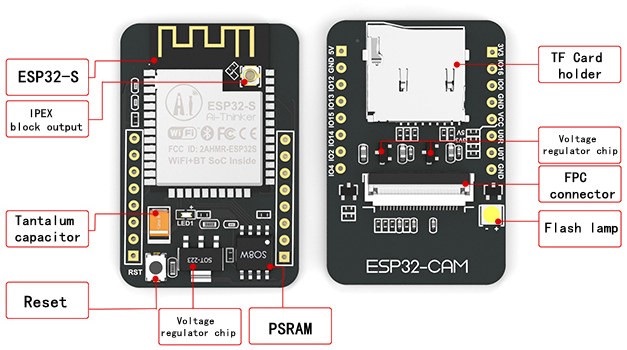


 The following code should load.
 Before uploading the code, you need to insert your network credentials in the following variables:

 You also have the option to take photos by clicking the
  First, you need to enroll a new face. It will make several attempts to save the face. After enrolling a new user, it should detect the face later on (subject 0).
 And that's it. Now you have your video streaming web server up and running with face detection and recognition with the example from the library.
 This guide is also fully compatible with the ESP8266 board. However, since Wi-Fi manager library uses quite a lot of memory you may encounter a memory error while saving the script to your board. From our experience, restarting the board after uploading the script, removes the error and makes the project work after that. We recommend using the ESP32, but you can also continue this tutorial using an ESP8266 board.
 Here's how the process works:
When the ESP32 boots for the first time, it's set as an Access Point;
You can connect to that Access Point by establishing a connection with the WiFiManager network and going to the IP address 192.164.4.1;
A web page opens that allows you to choose and configure a network;
The ESP32 saves those network credentials so that later it can connect to that network (Station mode);
Once a new SSID and password is set, the ESP32 reboots, it is set to Station mode and tries to connect to the previously saved network;
If it establishes a connection, the process is completed successfully. Otherwise, it will be set up as an Access Point for you to configure new network credentials.
To set up the Wi-Fi Manager on the ESP32 using MicroPython, we'll use the WiFiManager library by tayfunulu. In the library GitHub page, you can find the following diagram that shows an overview on how everything works.
Here's how the process works:
When the ESP32 boots for the first time, it's set as an Access Point;
You can connect to that Access Point by establishing a connection with the WiFiManager network and going to the IP address 192.164.4.1;
A web page opens that allows you to choose and configure a network;
The ESP32 saves those network credentials so that later it can connect to that network (Station mode);
Once a new SSID and password is set, the ESP32 reboots, it is set to Station mode and tries to connect to the previously saved network;
If it establishes a connection, the process is completed successfully. Otherwise, it will be set up as an Access Point for you to configure new network credentials.
To set up the Wi-Fi Manager on the ESP32 using MicroPython, we'll use the WiFiManager library by tayfunulu. In the library GitHub page, you can find the following diagram that shows an overview on how everything works.


 The file should be saved on the device folder with the name wifimgr.py as highlighted in the following figure.
 Now, you can use the library functionalities in your code by importing the library.
 And that's it. The library was uploaded to your board. To make sure that it was uploaded successfully, in the Shell you can type:
 After uploading the library to your board, you can use the library functionalities in your code by importing the library.
 That means that the ESP32 was successfully set as an Access Point. Now, you can connect to that Access Point to choose your network and type your credentials. To do that, follow the next steps.
In your computer, or smartphone, open the Wi-Fi settings and connect to the
That means that the ESP32 was successfully set as an Access Point. Now, you can connect to that Access Point to choose your network and type your credentials. To do that, follow the next steps.
In your computer, or smartphone, open the Wi-Fi settings and connect to the  The password is
  Once you're successfully connected to the WiFiManager network, open a browser and type 192.168.4.1. The following page should load:
 Select your network, type the password and click
  This message means that your ESP32 is set up as a Wi-Fi Station and it is connected to your local network. Now, to access the ESP32, go again to your Wi-Fi settings in your computer or smartphone and connect again to your network.
In the Python shell, the ESP32 IP address should be printed.
This message means that your ESP32 is set up as a Wi-Fi Station and it is connected to your local network. Now, to access the ESP32, go again to your Wi-Fi settings in your computer or smartphone and connect again to your network.
In the Python shell, the ESP32 IP address should be printed.


 With this project you'll learn how to:
Send sensor readings via LoRa radio between two ESP32 boards;
Add LoRa and Wi-Fi capabilities simultaneously to your projects (LoRa + Web Server on the same ESP32 board);
Use the TTGO LoRa32 SX1276 OLED board or similar development boards for IoT projects.
With this project you'll learn how to:
Send sensor readings via LoRa radio between two ESP32 boards;
Add LoRa and Wi-Fi capabilities simultaneously to your projects (LoRa + Web Server on the same ESP32 board);
Use the TTGO LoRa32 SX1276 OLED board or similar development boards for IoT projects.
 The LoRa sender sends BME280 sensor readings via LoRa radio every 10 seconds;
The LoRa receiver gets the readings and displays them on a web server;
You can monitor the sensor readings by accessing the web server;
The LoRa sender and the Lora receiver can be several hundred meters apart depending on their location. So, you can use this project to monitor sensor readings from your fields or greenhouses if they are a bit apart from your house;
The LoRa receiver is running an asynchronous web server and the web page files are saved on the ESP32 filesystem (SPIFFS);
The LoRa receiver also shows the date and time the last readings were received. To get date and time, we use the Network Time Protocol with the ESP32.
The LoRa sender sends BME280 sensor readings via LoRa radio every 10 seconds;
The LoRa receiver gets the readings and displays them on a web server;
You can monitor the sensor readings by accessing the web server;
The LoRa sender and the Lora receiver can be several hundred meters apart depending on their location. So, you can use this project to monitor sensor readings from your fields or greenhouses if they are a bit apart from your house;
The LoRa receiver is running an asynchronous web server and the web page files are saved on the ESP32 filesystem (SPIFFS);
The LoRa receiver also shows the date and time the last readings were received. To get date and time, we use the Network Time Protocol with the ESP32.


 Finally, press the upload button.
 Open the Serial Monitor at a baud rate of 115200. You should get something as shown below.
 The OLED of your board should be displaying the latest sensor readings.
 Your LoRa Sender is ready. Now, let's move on to the LoRa Receiver.
 As you can see, it contains a background image and styles to make the web page more appealing. There are several ways to display images on an ESP32 web server. We'll store the image on the ESP32 filesystem (SPIFFS). We'll also store the HTML file on SPIFFS.

 After a few seconds, the files should be successfully uploaded to SPIFFS.
 You should also get the IP address displayed on the OLED.

 With these boards we were able to get a stable LoRa communication up to 180 meters (590 ft) in open field. These means that we can have the sender and receiver 180 meters apart and we're still able to get and check the readings on the web server.
 Getting a stable communication at a distance of 180 meters with such low cost boards and without any further customization is really impressive.
However, in a previous project using an RFM95 SX1276 LoRa transceiver chip with an home made antenna, we got better results: more than 250 meters with many obstacles in between.
Getting a stable communication at a distance of 180 meters with such low cost boards and without any further customization is really impressive.
However, in a previous project using an RFM95 SX1276 LoRa transceiver chip with an home made antenna, we got better results: more than 250 meters with many obstacles in between.
 The communication range will really depend on your environment, the LoRa board you're using and many other variables.
 We have other ESP32-CAM projects in our blog that you might like. In fact you can take this project further, by adding a PIR sensor to take a photo when motion is detected, a physical pushbutton to take a photo, or also include video streaming capabilities in another URL path.
Other ESP32-CAM projects and tutorials:
ESP32-CAM PIR Motion Detector with Photo Capture (saves to microSD card)
ESP32-CAM Video Streaming and Face Recognition with Arduino IDE
ESP32-CAM Video Streaming Web Server (Home Assistant, Node-RED, etc)
ESP32-CAM Take Photo and Save to MicroSD Card
ESP32-CAM Troubleshooting Guide
We have other ESP32-CAM projects in our blog that you might like. In fact you can take this project further, by adding a PIR sensor to take a photo when motion is detected, a physical pushbutton to take a photo, or also include video streaming capabilities in another URL path.
Other ESP32-CAM projects and tutorials:
ESP32-CAM PIR Motion Detector with Photo Capture (saves to microSD card)
ESP32-CAM Video Streaming and Face Recognition with Arduino IDE
ESP32-CAM Video Streaming Web Server (Home Assistant, Node-RED, etc)
ESP32-CAM Take Photo and Save to MicroSD Card
ESP32-CAM Troubleshooting Guide
 When you access the web server, you'll see three buttons:

 In your Arduino IDE Serial Monitor window, you should see similar messages:

 For an introduction to LoRa communication, read: ESP32 with LoRa using Arduino IDE.

 The OLED displays communicates using I2C communication protocol. It is internally connected to the ESP32 on the following pins:
 3. After installing the SSD1306 library from Adafruit, type
 After installing the libraries, restart your Arduino IDE.
 After uploading the code to your board, it should start sending LoRa packets.


 An
An  The PCB we'll build is very versatile and it can be used with an ESP32, ESP32-CAM, ESP8266, Arduino or any other microcontroller.
 You can power it with a battery, rechargeable batteries + solar panels, or any voltage source.
 It can be turned on by different triggers for example from a pushbutton press, motion detected by a PIR sensor, a magnetic reed switch, or any other digital sensor.


 You send a HIGH signal to the TRIGGER pin (
 To keep your microcontroller powered on, you need to send a HIGH signal from one of its GPIOs to the LATCH pin (labeled as IN) (
 When you're done with that task, you can cut the power by sending a LOW signal to the LATCH PIN (
 If you want to customize your PCB, you just need to upload the following files:
EasyEDA project files to edit the PCB
Or you can simply download the Gerber files that I've used and order the final PCBs yourself.
In my opinion, the most important step when creating a PCB is to first ensure your circuit actually works on a breadboard or stripboard before designing the circuit.
If you want to customize your PCB, you just need to upload the following files:
EasyEDA project files to edit the PCB
Or you can simply download the Gerber files that I've used and order the final PCBs yourself.
In my opinion, the most important step when creating a PCB is to first ensure your circuit actually works on a breadboard or stripboard before designing the circuit.
 Creating the circuit works like in any other circuit software tool, you place some components and you wire them together. When you're happy with your circuit and pins usage, make sure you assign each component to a footprint.

 Once you're done, save your project and generate the Gerber files.
 This software allows you to automatically order your PCBs from JLCPCB. Alternatively, you can also follow the next steps to order the exact PCBs we've built.


 To build your PCB and follow this tutorial, you need the following parts:
Microcontroller or Development Board, for example:
ESP32 Dev Board (read ESP32 boards review)
ESP8266 NodeMCU (read ESP8266 boards review)
Arduino UNO (read best Arduino Starter Kits)
AO3413 SMD Transistor P-Channel MOSFET
2x 2N3904 SMD Transistor BJT NPN
SMD Resistors: 220K Ohm, 2x 100K Ohm, 2x 10K Ohm, 1K Ohm, 330 Ohm, and 220 Ohm (1206 package)
SMD LED (1206 package)
2x SMD Diodes (for example: 1N5819W)
PIR motion sensor (or reed switch, pushbutton, etc)
Power Supply
You can use the preceding links or go directly to MakerAdvisor.com/tools to find all the parts for your projects at the best price!
To build your PCB and follow this tutorial, you need the following parts:
Microcontroller or Development Board, for example:
ESP32 Dev Board (read ESP32 boards review)
ESP8266 NodeMCU (read ESP8266 boards review)
Arduino UNO (read best Arduino Starter Kits)
AO3413 SMD Transistor P-Channel MOSFET
2x 2N3904 SMD Transistor BJT NPN
SMD Resistors: 220K Ohm, 2x 100K Ohm, 2x 10K Ohm, 1K Ohm, 330 Ohm, and 220 Ohm (1206 package)
SMD LED (1206 package)
2x SMD Diodes (for example: 1N5819W)
PIR motion sensor (or reed switch, pushbutton, etc)
Power Supply
You can use the preceding links or go directly to MakerAdvisor.com/tools to find all the parts for your projects at the best price!

 As usual, everything comes very well packaged and the PCBs are really high quality, specially the silkscreen.

 To solder the PCBs, I've used the TS80 soldering iron. The TS80 soldering iron is the TS100 successor. I have a review about the TS100 soldering iron. I didn't have time yet to write a review about the TS80, but it's by far the best portable soldering iron I've used.


 In the setup(), define the powerLatch and led pins as outputs.
 When the ESP32 is on, the whole circuit consumes about 65 mA.
 After 10 seconds, the ESP32 turns off. If we measure the power consumption, you can see that the ESP32 is not consuming any power. It's completely powered off.
 This would work exactly the same for an ESP8266, Arduino, STM32 or any other microcontroller.
The PIR motion sensor consumes very little power, about 14 uA. So, even with a small battery it would last years. But if you're using a pushbutton or a reed switch,
This would work exactly the same for an ESP8266, Arduino, STM32 or any other microcontroller.
The PIR motion sensor consumes very little power, about 14 uA. So, even with a small battery it would last years. But if you're using a pushbutton or a reed switch, 
 In this tutorial, we'll cover the following concepts:
Connecting I2C Devices with ESP32
Scan I2C Address with ESP32
Use Different I2C Pins with ESP32 (change default I2C pins)
ESP32 with Multiple I2C Devicessame bus, different addresses
same address
ESP32 Using Two I2C Bus Interfaces
We'll program the ESP32 using Arduino IDE, so before proceeding with this tutorial you should have the ESP32 add-on installed in your Arduino IDE. Follow the next tutorial to install the ESP32 on the Arduino IDE, if you haven't already.
Installing the ESP32 Board in Arduino IDE (Windows, Mac OS X, and Linux instructions)
In this tutorial, we'll cover the following concepts:
Connecting I2C Devices with ESP32
Scan I2C Address with ESP32
Use Different I2C Pins with ESP32 (change default I2C pins)
ESP32 with Multiple I2C Devicessame bus, different addresses
same address
ESP32 Using Two I2C Bus Interfaces
We'll program the ESP32 using Arduino IDE, so before proceeding with this tutorial you should have the ESP32 add-on installed in your Arduino IDE. Follow the next tutorial to install the ESP32 on the Arduino IDE, if you haven't already.
Installing the ESP32 Board in Arduino IDE (Windows, Mac OS X, and Linux instructions)

 The SDA and SCL lines are active low, so they should be pulled up with resistors. Typical values are 4.7k Ohm for 5V devices and 2.4k Ohm for 3.3V devices.
Most sensors we use in our projects are breakout boards that already have the resistors built-in. So, usually, when you're dealing with this type of electronics components you don't need to worry about this.
Connecting an I2C device to an ESP32 is normally as simple as connecting GND to GND, SDA to SDA, SCL to SCL and a positive power supply to a peripheral, usually 3.3V (but it depends on the module you're using).
The SDA and SCL lines are active low, so they should be pulled up with resistors. Typical values are 4.7k Ohm for 5V devices and 2.4k Ohm for 3.3V devices.
Most sensors we use in our projects are breakout boards that already have the resistors built-in. So, usually, when you're dealing with this type of electronics components you don't need to worry about this.
Connecting an I2C device to an ESP32 is normally as simple as connecting GND to GND, SDA to SDA, SCL to SCL and a positive power supply to a peripheral, usually 3.3V (but it depends on the module you're using).

 So, the example sketch to read from the BME280 using other pins, for example GPIO 33 as SDA and and GPIO 32 as SCL is as follows.


 In this example, we'll use a DS18B20 temperature sensor, and we'll send a text message when the temperature is above 28oC. Once the temperature has decreased below the threshold, we'll send another SMS alert.
To send an SMS with the T-Call ESP32 SIM800L module, you just need to use modem.sendSMS(SMS_TARGET, smsMessage) after initializing a modem object for the SIM800L module (using the TinyGSM library).
In this example, we'll use a DS18B20 temperature sensor, and we'll send a text message when the temperature is above 28oC. Once the temperature has decreased below the threshold, we'll send another SMS alert.
To send an SMS with the T-Call ESP32 SIM800L module, you just need to use modem.sendSMS(SMS_TARGET, smsMessage) after initializing a modem object for the SIM800L module (using the TinyGSM library).

 Besides Wi-Fi and Bluetooth, you can communicate with this ESP32 board using SMS, phone calls or you can connect it to the internet. In this tutorial, you'll learn how to send an SMS notification.
For a complete overview of this board, you can read the following article: $11 TTGO T-Call ESP32 with SIM800L GSM/GPRS (Overview)
Besides Wi-Fi and Bluetooth, you can communicate with this ESP32 board using SMS, phone calls or you can connect it to the internet. In this tutorial, you'll learn how to send an SMS notification.
For a complete overview of this board, you can read the following article: $11 TTGO T-Call ESP32 with SIM800L GSM/GPRS (Overview)


 Then, search for
  After installing the libraries, restart your Arduino IDE.
 To follow this tutorial you need the following parts:

 After a few seconds, you should receive an SMS on the recipient's phone number.


 When the temperature goes below the threshold, I'll receive another SMS.


 Besides Wi-Fi and Bluetooth, you can communicate with this ESP32 board using SMS or phone calls and you can connect it to the internet using your SIM card data plan. This is great for IoT projects that don't have access to a nearby router.
 The package includes some header pins, a battery connector, and an external antenna that you should connect to your board.
 However, we had some issues with that antenna, so we decided to switch to another type of antenna and all the problems were solved. The following figure shows the new antenna.


 We're connecting the SDA pin to GPIO 18 and the SCL pin to GPIO 19. We're not using the default I2C GPIOs because they are being used by the battery power management IC of the T-Call ESP32 SIM800L board.
 In this example, it publishes new sensor readings every 60 minutes, but for testing purposes you can use a shorter delay.
Then, open a browser and type your server domain on the
In this example, it publishes new sensor readings every 60 minutes, but for testing purposes you can use a shorter delay.
Then, open a browser and type your server domain on the 


 Let's take a look at the first form to see how it works (the other forms work in a similar way).
 If you make a request on an invalid URL, we call the notFound() function, defined at the beginning of the sketch.
 Then, open your browser and type the IP address. This web page should load:
 For example, type

 Type a String in the first input field and press Submit, repeat the same process for the Int and Float input values. Every time you press the Submit button for a field, you'll see an alert message like this:
 Press the OK button to reload the web page and see the current values updated.
If you have your Arduino IDE Serial Monitor open, you'll see that the stored values are being printed over and over again:
Press the OK button to reload the web page and see the current values updated.
If you have your Arduino IDE Serial Monitor open, you'll see that the stored values are being printed over and over again:
 For a final project, you can delete all those lines in your loop() that print all stored values every 5 seconds, we just left them on purpose for debugging.

 A hall effect sensor can detect variations in the magnetic field in its surroundings. The greater the magnetic field, the greater the sensor's output voltage.
 The hall effect sensor can be combined with a threshold detection to act as a switch, for example. Additionally, hall effect sensors are mainly used to:
Detect proximity;
Calculate positioning;
Count the number of revolutions of a wheel;
Detect a door closing;
And much more.
The hall effect sensor can be combined with a threshold detection to act as a switch, for example. Additionally, hall effect sensors are mainly used to:
Detect proximity;
Calculate positioning;
Count the number of revolutions of a wheel;
Detect a door closing;
And much more.
 Or decreasing depending on the magnet pole that is facing the sensor:
The closer the magnet is to the sensor, the greater the absolute values are.
Or decreasing depending on the magnet pole that is facing the sensor:
The closer the magnet is to the sensor, the greater the absolute values are.

 The web server we'll build updates the readings automatically without the need to refresh the web page.
With this project you'll learn:
How to read temperature and humidity from DHT sensors;
Build an asynchronous web server using the ESPAsyncWebServer library;
Update the sensor readings automatically without the need to refresh the web page.
For a more in-depth explanation on how to use the DHT22 and DHT11 temperature and humidity sensors with the ESP32, read our complete guide: ESP32 with DHT11/DHT22 Temperature and Humidity Sensor using Arduino IDE
The web server we'll build updates the readings automatically without the need to refresh the web page.
With this project you'll learn:
How to read temperature and humidity from DHT sensors;
Build an asynchronous web server using the ESPAsyncWebServer library;
Update the sensor readings automatically without the need to refresh the web page.
For a more in-depth explanation on how to use the DHT22 and DHT11 temperature and humidity sensors with the ESP32, read our complete guide: ESP32 with DHT11/DHT22 Temperature and Humidity Sensor using Arduino IDE
 To complete this tutorial you need the following parts:
ESP32 development board (read ESP32 development boards comparison)
DHT22 or DHT11 Temperature and Humidity Sensor
4.7k Ohm Resistor
Breadboard
Jumper wires
You can use the preceding links or go directly to MakerAdvisor.com/tools to find all the parts for your projects at the best price!
To complete this tutorial you need the following parts:
ESP32 development board (read ESP32 development boards comparison)
DHT22 or DHT11 Temperature and Humidity Sensor
4.7k Ohm Resistor
Breadboard
Jumper wires
You can use the preceding links or go directly to MakerAdvisor.com/tools to find all the parts for your projects at the best price!

 As you can see in the above figure, the web page shows one heading and two paragraphs. There is a paragraph to display the temperature and another to display the humidity. There are also two icons to style our page.
Let's see how this web page is created.
All the HTML text with styles included is stored in the index_html variable. Now we'll go through the HTML text and see what each part does.
The following <meta> tag makes your web page responsive in any browser.
As you can see in the above figure, the web page shows one heading and two paragraphs. There is a paragraph to display the temperature and another to display the humidity. There are also two icons to style our page.
Let's see how this web page is created.
All the HTML text with styles included is stored in the index_html variable. Now we'll go through the HTML text and see what each part does.
The following <meta> tag makes your web page responsive in any browser.
 Search the icon you're looking for. For example, thermometer.
 Click the desired icon. Then, you just need to copy the HTML text provided.
 To chose the color, you just need to pass the style parameter with the color in hexadecimal, as follows:


 Before proceeding with this tutorial you should have the ESP32 add-on installed in your Arduino IDE. Follow one of the following tutorials to install the ESP32 on the Arduino IDE, if you haven't already.
Installing the ESP32 Board in Arduino IDE (Windows, Mac OS X, and Linux instructions)
You might also like reading other BME280 guides:
ESP32 with BME280 Sensor using Arduino IDE
ESP8266 with BME280 using Arduino IDE
ESP32/ESP8266 with BME280 using MicroPython
Arduino Board with BME280
Before proceeding with this tutorial you should have the ESP32 add-on installed in your Arduino IDE. Follow one of the following tutorials to install the ESP32 on the Arduino IDE, if you haven't already.
Installing the ESP32 Board in Arduino IDE (Windows, Mac OS X, and Linux instructions)
You might also like reading other BME280 guides:
ESP32 with BME280 Sensor using Arduino IDE
ESP8266 with BME280 using Arduino IDE
ESP32/ESP8266 with BME280 using MicroPython
Arduino Board with BME280
 The sensor can communicate using either SPI or I2C communication protocols (there are modules of this sensor that just communicate with I2C, these just come with four pins).
To use SPI communication protocol, you use the following pins:
SCK this is the SPI Clock pin
SDO MISO
SDI MOSI
CS Chip Select
To use I2C communication protocol, the sensor uses the following pins:
SCK this is also the SCL pin
SDI this is also the SDA pin
The sensor can communicate using either SPI or I2C communication protocols (there are modules of this sensor that just communicate with I2C, these just come with four pins).
To use SPI communication protocol, you use the following pins:
SCK this is the SPI Clock pin
SDO MISO
SDI MOSI
CS Chip Select
To use I2C communication protocol, the sensor uses the following pins:
SCK this is also the SCL pin
SDI this is also the SDA pin

 After installing the BME280 library, and the Adafruit_Sensor library, open the Arduino IDE and, go to
 The table doesn't have any styles applied. You can use CSS to style the table with your own preferences. You may found this link useful: CSS Styling Tables.
 Open your browser, paste the IP address, and you should see the latest sensor readings. To update the readings, you just need to refresh the web page.


 To follow this tutorial you need the following parts:
ESP32 or ESP8266 (read ESP32 vs ESP8266)
BME280 sensor
Breadboard
Jumper wires
You can use the preceding links or go directly to MakerAdvisor.com/tools to find all the parts for your projects at the best price!
To follow this tutorial you need the following parts:
ESP32 or ESP8266 (read ESP32 vs ESP8266)
BME280 sensor
Breadboard
Jumper wires
You can use the preceding links or go directly to MakerAdvisor.com/tools to find all the parts for your projects at the best price!


 You can select each point to see the exact timestamp.

 You might also like reading other DS18B20 guides:
ESP8266 DS18B20 Temperature Sensor with Arduino IDE
ESP32/ESP8266 DS18B20 Temperature Sensor with MicroPython
ESP32 with Multiple DS18B20 Temperature Sensors
DS18B20 Temperature Sensor with Arduino
You might also like reading other DS18B20 guides:
ESP8266 DS18B20 Temperature Sensor with Arduino IDE
ESP32/ESP8266 DS18B20 Temperature Sensor with MicroPython
ESP32 with Multiple DS18B20 Temperature Sensors
DS18B20 Temperature Sensor with Arduino
 Each DS18B20 temperature sensor has a unique 64-bit serial code. This allows you to wire multiple sensors to the same data wire. So, you can get temperature from multiple sensors using just one GPIO.
The DS18B20 temperature sensor is also available in waterproof version.
Each DS18B20 temperature sensor has a unique 64-bit serial code. This allows you to wire multiple sensors to the same data wire. So, you can get temperature from multiple sensors using just one GPIO.
The DS18B20 temperature sensor is also available in waterproof version.
 Here's a summary of the most relevant specs of the DS18B20 temperature sensor:
Communicates over one-wire bus communication
Power supply range: 3.0V to 5.5V
Operating temperature range: -55oC to +125oC
Accuracy +/-0.5 oC (between the range -10oC to 85oC)
For more information consult the DS18B20 datasheet.
Here's a summary of the most relevant specs of the DS18B20 temperature sensor:
Communicates over one-wire bus communication
Power supply range: 3.0V to 5.5V
Operating temperature range: -55oC to +125oC
Accuracy +/-0.5 oC (between the range -10oC to 85oC)
For more information consult the DS18B20 datasheet.


 The DS18B20 temperature sensor communicates using one-wire protocol and each sensor has a unique 64-bit serial code, so you can read the temperature from multiple sensors using just one single GPIO. You just need to wire all data lines together as shown in the following schematic diagram:

 We have a dedicated article on how to interface multiple DS18B20 temperature sensors with the EPS32. Just follow the next tutorial:
ESP32 with Multiple DS18B20 Temperature Sensors
We have a dedicated article on how to interface multiple DS18B20 temperature sensors with the EPS32. Just follow the next tutorial:
ESP32 with Multiple DS18B20 Temperature Sensors

 To build the web server we'll use the ESPAsyncWebServer library that provides an easy way to build an asynchronous web server. Building an asynchronous web server has several advantages. We recommend taking a quick look at the library documentation on its GitHub page.

 Note: there's also a waterproof version of the DS18B20 temperature sensor.
Here's the main specifications of the DS18B20 temperature sensor:
Comunicates over 1-wire bus communication
Operating range temperature: -55oC to 125oC
Accuracy +/-0.5 oC (between the range -10oC to 85oC)
From left to right: the first pin is GND, the second is data, and the rightmost pin is VCC.
Note: there's also a waterproof version of the DS18B20 temperature sensor.
Here's the main specifications of the DS18B20 temperature sensor:
Comunicates over 1-wire bus communication
Operating range temperature: -55oC to 125oC
Accuracy +/-0.5 oC (between the range -10oC to 85oC)
From left to right: the first pin is GND, the second is data, and the rightmost pin is VCC.
 ESP32 DOIT DEVKIT V1 Board read ESP32 Development Boards Review and Comparison
DS18B20 temperature sensor (we're using 3 sensors in this example)
4.7k Ohm resistor
Jumper wires
Breadboard
You can use the preceding links or go directly to MakerAdvisor.com/tools to find all the parts for your projects at the best price!
ESP32 DOIT DEVKIT V1 Board read ESP32 Development Boards Review and Comparison
DS18B20 temperature sensor (we're using 3 sensors in this example)
4.7k Ohm resistor
Jumper wires
Breadboard
You can use the preceding links or go directly to MakerAdvisor.com/tools to find all the parts for your projects at the best price!
 In the previous schematic, the round side of the sensor is facing backwards. The flat part is facing forward.
 Untick the
  The example code below reads temperature in Celsius and Fahrenheit from each sensor and prints the results in the Serial Monitor.


 As a regular ESP32 board, it features a BOOT and a EN (RST) button. Some models have the buttons at the back, some have both at the front, and others have one at the front and other at the back. However, all boards should work in a similar way.


 Inside that folder, create a new folder called
  Inside the


 Drag and drop your images. You can upload up to 20 images at the same time. For this example we'll be using the following six images.
 Then, copy the data from the first field. That's what you need to use as source in your <img src=> HTML tag.


 Enter the following into the Additional Board Manager URLs field:
https://raw.githubusercontent.com/espressif/arduino-esp32/gh-pages/package_esp32_index.json
Then, click the OK button:
Enter the following into the Additional Board Manager URLs field:
https://raw.githubusercontent.com/espressif/arduino-esp32/gh-pages/package_esp32_index.json
Then, click the OK button:

 Search for
  That's it. It should be installed after a few seconds.

 2. Select the Port (if you don't see the COM Port in your Arduino IDE, you need to install the CP210x USB to UART Bridge VCP Drivers):
 3. Open the following example under
  4. A new sketch opens in your Arduino IDE:
 5. Press the
  7. Open the Arduino IDE Serial Monitor at a baud rate of 115200:
 8. Press the ESP32 on-board
 Press the
  After that, you should see the
  We'll show you how to wire the sensor to the ESP32, install the required libraries, and write a simple sketch that displays the sensor readings.
 This sensor communicates using I2C communication protocol, so the wiring is very simple. You can use the default ESP32 I2C pins as shown in the following table:
 If you're using one of these sensors, to use I2C communication protocol, use the following pins:


 To read the value of the ESP32 touch pins, use the touchRead(GPIO) function, that accepts as argument, the GPIO you want to read.

 You can also use the serial plotter to better see the values. Close the serial monitor, go to
 With the previous code running, go back to the serial monitor.
Now, touch the aluminium foil, and you'll see the values changing again.
With the previous code running, go back to the serial monitor.
Now, touch the aluminium foil, and you'll see the values changing again.
 In our case, when we're not touching the pin, the normal value is above 70. And when we touch the aluminum foil it drops to some value below 10.
So, we can set a threshold value, and when the reading goes below that value, an LED lights up. A good threshold value in this case is 20, for example.
In our case, when we're not touching the pin, the normal value is above 70. And when we touch the aluminum foil it drops to some value below 10.
So, we can set a threshold value, and when the reading goes below that value, an LED lights up. A good threshold value in this case is 20, for example.


 Reading analog inputs with the ESP32 is as easy as using the analogRead(GPIO) function, that accepts as argument, the GPIO you want to read.
We also have other tutorials on how to use analog pins with ESP board:
ESP8266 ADC Read Analog Values with Arduino IDE, MicroPython and Lua
ESP32 Analog Readings with MicroPython
Reading analog inputs with the ESP32 is as easy as using the analogRead(GPIO) function, that accepts as argument, the GPIO you want to read.
We also have other tutorials on how to use analog pins with ESP board:
ESP8266 ADC Read Analog Values with Arduino IDE, MicroPython and Lua
ESP32 Analog Readings with MicroPython


 Learn more about the ESP32 GPIOs: ESP32 Pinout Reference.
These analog input pins have 12-bit resolution. This means that when you read an analog input, its range may vary from 0 to 4095.
Learn more about the ESP32 GPIOs: ESP32 Pinout Reference.
These analog input pins have 12-bit resolution. This means that when you read an analog input, its range may vary from 0 to 4095.

 The maximum value you'll get is 4095 and the minimum value is 0.

 The idea of using the OLED display with the ESP32 or ESP8266 is to ilustrate how you can create a physical user interface for your boards.
 The temperature and humidity will be measured using the DHT22 temperature and humidity sensor (you can also use DHT11).
 If you're not familiar with the DHT11/DHT22 sensor, we recommend reading the following guide:
ESP32 with DHT11/DHT22 Sensor (Arduino IDE)
If you're not familiar with the DHT11/DHT22 sensor, we recommend reading the following guide:
ESP32 with DHT11/DHT22 Sensor (Arduino IDE)


 Additionally, BLE supports not only point-to-point communication, but also broadcast mode, and mesh network.
Take a look at the table below that compares BLE and Bluetooth Classic in more detail.
Additionally, BLE supports not only point-to-point communication, but also broadcast mode, and mesh network.
Take a look at the table below that compares BLE and Bluetooth Classic in more detail.
 View Image Souce
Due to its properties, BLE is suitable for applications that need to exchange small amounts of data periodically running on a coin cell. For example, BLE is of great use in healthcare, fitness, tracking, beacons, security, and home automation industries.
View Image Souce
Due to its properties, BLE is suitable for applications that need to exchange small amounts of data periodically running on a coin cell. For example, BLE is of great use in healthcare, fitness, tracking, beacons, security, and home automation industries.

 As mentioned previously, BLE also supports broadcast mode and mesh network:

 View Image Souce

 Go to the Serial Monitor with the ESP32 running the BLE_scan example, press the ESP32 (with the BLE_scan sketch) ENABLE button to restart and wait a few seconds while it scans.
 The scanner found two devices: one is the ESP32 (it has the name
 Don't forget go to the Bluetooth settings and enable Bluetooth adapter in your smartphone. You may also want to make it visible to other devices to test other sketches later on.
 Once everything is ready in your smartphone and the ESP32 is running the BLE server sketch, in the app, tap the scan button to scan for nearby devices. You should find an ESP32 with the name
  Click the
  The characteristic has the READ and WRITE properties, and the value is the one you've previously defined in the BLE server sketch. So, everything is working fine.

 It features a measuring range from 300 to 1100hPa with an accuracy down to 0.02 hPa.
Because temperature affects the pressure, the sensor comes with a temperature sensor to give temperature compensated pressure readings.
Additionally, because the pressure changes with altitude, you can also estimate the altitude based on the current pressure measurement.
It features a measuring range from 300 to 1100hPa with an accuracy down to 0.02 hPa.
Because temperature affects the pressure, the sensor comes with a temperature sensor to give temperature compensated pressure readings.
Additionally, because the pressure changes with altitude, you can also estimate the altitude based on the current pressure measurement.

 After installing, restart your Arduino IDE.
 Then, open the Serial Monitor at a baud rate of 9600. You should get the sensor readings, as shown in the following figure.


 On the ESP8266, the pin marked as D1 corresponds to GPIO 5 and the pin marked as D2 corresponds to GPIO 4.

 Getting analog readings with ESP32 and ESP8266 is a bit different, so there is a section for each board in this tutorial.
 The following table shows some differences between analog reading on the ESP8266 and the ESP32.
 In this example we're using GPIO 34 to read analog values from the potentiometer, but you can choose any other GPIO that supports ADC. Read our ESP32 Pinout Guide to learn more about the ESP32 GPIOs.
 The ESP8266 supports analog reading only on the A0 pin.
 Check the shell of your MicroPython IDE to read the values from the potentiometer. If you're using an ESP32 you should get readings between 0 and 4095 or readings between 0 and 1023 with an ESP8266.

 To learn more about deep sleep and other wake up sources, you can follow the next tutorials:
 The ESP32 RTC controller has a built-in timer you can use to wake up the ESP32 after a predefined amount of time.
 Every 5 seconds, the ESP32 wakes up, prints a message on the serial monitor, and goes to deep sleep again.
Every time the ESP32 wakes up, the bootCount variable increases. It also prints the wake up reason as shown in the figure below.
Every 5 seconds, the ESP32 wakes up, prints a message on the serial monitor, and goes to deep sleep again.
Every time the ESP32 wakes up, the bootCount variable increases. It also prints the wake up reason as shown in the figure below.
 However, notice that if you press the EN button on the ESP32 board, it resets the boot count to 1 again.
 The ESP32 can be awake from deep sleep using several wake up sources: timer, external wake up and touch wake up. This article shows how to use touch wake up.
To learn more about deep sleep and other wake up sources, you can follow the next tutorials:
The ESP32 can be awake from deep sleep using several wake up sources: timer, external wake up and touch wake up. This article shows how to use touch wake up.
To learn more about deep sleep and other wake up sources, you can follow the next tutorials:

 You can see that touch sensor 0 corresponds to GPIO 4, touch sensor 2 to GPIO 2, and so on.
 (This schematic uses the ESP32 DEVKIT V1 module version with 30 GPIOs if you're using another model, please check the pinout for the board you're using.)


 Throughout this article we'll cover the following subjects:
how to put the ESP32 in deep sleep mode;
wake up the ESP32 by changing the value of one GPIO (with a pushbutton) using the ext0 method;
wake up the ESP32 using several GPIOs using the ext1 method;
identify which GPIO caused the wake up.
To learn more about deep sleep and other wake up sources, you can follow the next tutorials:
Throughout this article we'll cover the following subjects:
how to put the ESP32 in deep sleep mode;
wake up the ESP32 by changing the value of one GPIO (with a pushbutton) using the ext0 method;
wake up the ESP32 using several GPIOs using the ext1 method;
identify which GPIO caused the wake up.
To learn more about deep sleep and other wake up sources, you can follow the next tutorials:

 (This schematic uses the ESP32 DEVKIT V1 module version with 30 GPIOs if you're using another model, please check the pinout for the board you're using.)
 Try this several times, and see the boot count increasing in each button press.
 Using this method is useful to wake up your ESP32 using a pushbutton, for example, to make a certain task. However, with this method you can only use one GPIO as wake up source.
What if you want to have different buttons, all of them wake up the ESP, but do different tasks? For that you need to use the ext1 method.
Using this method is useful to wake up your ESP32 using a pushbutton, for example, to make a certain task. However, with this method you can only use one GPIO as wake up source.
What if you want to have different buttons, all of them wake up the ESP, but do different tasks? For that you need to use the ext1 method.
 3. Copy the Hex number to the BUTTON_PIN_BITMASK variable, and you should get:

 Open the Serial Monitor at a baud rate of 115200. Press the pushbuttons to wake up the ESP32.
You should get something similar on the serial monitor.
Open the Serial Monitor at a baud rate of 115200. Press the pushbuttons to wake up the ESP32.
You should get something similar on the serial monitor.


 This is especially useful to trigger an action whenever motion is detected or whenever a pushbutton is pressed without the need for constantly checking its state.


 After 20 seconds the LED turns off.

 The ESP32 Espressif datasheet also provides a table comparing the power consumption of the different power modes.
 And here's also
 If you put your ESP32 in deep sleep mode, it will reduce the power consumption and your batteries will last longer.
Having your ESP32 in deep sleep mode means cutting with the activities that consume more power while operating, but leave just enough activity to wake up the processor when something interesting happens.
In deep sleep mode neither CPU or Wi-Fi activities take place, but the Ultra Low Power (ULP) co-processor can still be powered on.
While the ESP32 is in deep sleep mode the RTC memory also remains powered on, so we can write a program for the ULP co-processor and store it in the RTC memory to access peripheral devices, internal timers, and internal sensors.
This mode of operation is useful if you need to wake up the main CPU by an external event, timer, or both, while maintaining minimal power consumption.
If you put your ESP32 in deep sleep mode, it will reduce the power consumption and your batteries will last longer.
Having your ESP32 in deep sleep mode means cutting with the activities that consume more power while operating, but leave just enough activity to wake up the processor when something interesting happens.
In deep sleep mode neither CPU or Wi-Fi activities take place, but the Ultra Low Power (ULP) co-processor can still be powered on.
While the ESP32 is in deep sleep mode the RTC memory also remains powered on, so we can write a program for the ULP co-processor and store it in the RTC memory to access peripheral devices, internal timers, and internal sensors.
This mode of operation is useful if you need to wake up the main CPU by an external event, timer, or both, while maintaining minimal power consumption.


 Before trying to upload a new code, you should check the connections with a multimeter in continuity mode check that you haven't inadvertently solder anything to the next pin.
 If everything is soldered properly, you won't need to press the BOOT button when uploading new code. You also won't get the Fatal Error Occurred: Failed to connect to ESP32: Timed out waiting for packet header.


 If at this moment you can't find your ESP32 board name, we recommend repeating the installation process from scratch.
 It might be one of these two problems:
  Go to Google and search for your particular chip to find the drivers and install them in your operating system.
 You can download the CP2102 drivers on the Silicon Labs website.
 After they are installed, restart the Arduino IDE and you should see the COM port in the Tools menu.


 The advantage of using an I2C LCD is that the wiring is really simple. You just need to wire the SDA and SCL pins.
Additionally, it comes with a built-in potentiometer you can use to adjust the contrast between the background and the characters on the LCD. On a regular LCD you need to add a potentiometer to the circuit to adjust the contrast.
The advantage of using an I2C LCD is that the wiring is really simple. You just need to wire the SDA and SCL pins.
Additionally, it comes with a built-in potentiometer you can use to adjust the contrast between the background and the characters on the LCD. On a regular LCD you need to add a potentiometer to the circuit to adjust the contrast.

 Wire your LCD to the ESP32 by following the next schematic diagram. We're using the ESP32 default I2C pins (GPIO 21 and GPIO 22).
 You can also use the following table as a reference.
 You can also use the following table as a reference.
 In this simple sketch we show you the most useful and important functions from the LiquidCrystal_I2C library. So, let's take a quick look at how the code works.

 Copy the byte variable to your code (before the setup()). You can call it heart:
 Alexa will respond to the following commands:
Alexa, turn on lamp 1
Alexa, turn off lamp 1
Alexa, turn on lamp 2
Alexa, turn on lamp 2
Alexa, turn on lamps turns on both lamps
Alexa, turn off lamps turns off both lamps
When you say something like Alexa, turn on lamp 1, the ESP8266 or ESP32 will trigger a relay to turn on lamp 1. When you say something like Alexa, turn off lamp 1, the ESP8266 or ESP32 will send a signal to the relay to turn off the lamp. This works similarly for lamp 2.
Alexa will respond to the following commands:
Alexa, turn on lamp 1
Alexa, turn off lamp 1
Alexa, turn on lamp 2
Alexa, turn on lamp 2
Alexa, turn on lamps turns on both lamps
Alexa, turn off lamps turns off both lamps
When you say something like Alexa, turn on lamp 1, the ESP8266 or ESP32 will trigger a relay to turn on lamp 1. When you say something like Alexa, turn off lamp 1, the ESP8266 or ESP32 will send a signal to the relay to turn off the lamp. This works similarly for lamp 2.

 ESP Board (you can use either ESP32 or ESP8266):
ESP8266 read Best ESP8266 Wi-Fi Development Boards
ESP32 we use the ESP32 DOIT DEVKIT V1 Board 36 GPIOs (read ESP32 development boards comparison)
Alexa Echo, Echo Show or Echo Dot
ESP Board (you can use either ESP32 or ESP8266):
ESP8266 read Best ESP8266 Wi-Fi Development Boards
ESP32 we use the ESP32 DOIT DEVKIT V1 Board 36 GPIOs (read ESP32 development boards comparison)
Alexa Echo, Echo Show or Echo Dot  Buying an Amazon Echo through Amazon is not possible for all countries. We provide links for Amazon in UK, USA, and Germany. If the Amazon Echo does not ship to your country through Amazon, you can get one from eBay (available worldwide).
 This wall panel switch has a push button in its circuit, as shown in the figure below, that when pressed emits a 433 MHz signal. You can use that signal to control whatever you want. This wall panel switch uses a 27A 12V type battery (not included in the package). So, you may want to buy one, when you get your wall panel switch.

 In my case:
switch 1:
In my case:
switch 1: 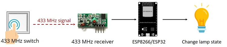


 Alternatively, you can also discover devices using the Amazon Alexa app, by following the steps shown in the figure below.
 Then, ask Alexa to turn on/off the lamps. You'll also get information about the lamps state on the Serial Monitor.
 After making sure everything is working properly, you can turn your circuit into a permanent solution.
 Now you can ask Alexa to control your lamps with the following voice commands:
Alexa, turn on lamp 1
Alexa, turn off lamp 1
Alexa, turn on lamp 2
Alexa, turn on lamp 2
You can also control both lamps at the same time by creating a group in the Amazon Alexa app. We called it lamps.
Now you can ask Alexa to control your lamps with the following voice commands:
Alexa, turn on lamp 1
Alexa, turn off lamp 1
Alexa, turn on lamp 2
Alexa, turn on lamp 2
You can also control both lamps at the same time by creating a group in the Amazon Alexa app. We called it lamps.
 Now, you can control both lamps at the same time, using the following voice commands.
Alexa, turn on lamps
Alexa, turn off lamps
You can also physically control your lamps using the 433 MHz wall panel switches.
Now, you can control both lamps at the same time, using the following voice commands.
Alexa, turn on lamps
Alexa, turn off lamps
You can also physically control your lamps using the 433 MHz wall panel switches.


 To use MQTT, you need a broker. We'll be using Mosquitto broker installed on a Raspberry Pi. Read How to Install Mosquitto Broker on Raspberry Pi.
If you're not familiar with MQTT make sure you read our introductory tutorial: What is MQTT and How It Works
To use MQTT, you need a broker. We'll be using Mosquitto broker installed on a Raspberry Pi. Read How to Install Mosquitto Broker on Raspberry Pi.
If you're not familiar with MQTT make sure you read our introductory tutorial: What is MQTT and How It Works
 ESP#1 publishes messages on the


 Now, you can use the library functionalities in your code by importing the library.
 On the other side, ESP#1 board should receive the received message. The received message is published by ESP#2 on the
 OTA programming is useful when you need to update code to ESP32 boards that are not easily accessible. The example we'll show here works when the ESP32 and your browser are on your local network.
The only disadvantage of the OTA Web Updater is that you have to add the code for OTA in every sketch you upload, so that you're able to use OTA in the future.
OTA programming is useful when you need to update code to ESP32 boards that are not easily accessible. The example we'll show here works when the ESP32 and your browser are on your local network.
The only disadvantage of the OTA Web Updater is that you have to add the code for OTA in every sketch you upload, so that you're able to use OTA in the future.
 The following code should load.
 Now, you can upload code to your ESP32 over-the-air using a browser on your local network.
To test the OTA Web Updater you can disconnect the ESP32 from your computer and power it using a power bank, for example (this is optional, we're suggesting this to mimic a situation in which the ESP32 is not connected to your computer).
Now, you can upload code to your ESP32 over-the-air using a browser on your local network.
To test the OTA Web Updater you can disconnect the ESP32 from your computer and power it using a power bank, for example (this is optional, we're suggesting this to mimic a situation in which the ESP32 is not connected to your computer).
 Enter the username and the password:

 A new file on the folder sketch should be created. Go to
 The ESP32 built-in LED should be blinking.
 Congratulations! You've uploaded a new code to your ESP32 over-the-air.


 You don't want this to happen. You want the ESP32 to remember what was happening before losing power and return to the last state.
To solve this problem, you can save the lamp's state in the flash memory. Then, you just need to add a condition at the beginning of your sketch to check the last lamp state, and turn the lamp on or off accordingly.
The following figure shows what we're going to do:
You don't want this to happen. You want the ESP32 to remember what was happening before losing power and return to the last state.
To solve this problem, you can save the lamp's state in the flash memory. Then, you just need to add a condition at the beginning of your sketch to check the last lamp state, and turn the lamp on or off accordingly.
The following figure shows what we're going to do:


 You should see the files on the ESP32/ESP8266 board on the device folder. By default, when you burn MicroPython firmware, a boot.py file is created.
For this project you'll need a boot.py file and a main.py file. The boot.py file has the code that only needs to run once on boot. This includes importing libraries, network credentials, instantiating pins, connecting to your network, and other configurations.
The main.py file will contain the code that runs the web server to serve files and perform tasks based on the requests received by the client.
You should see the files on the ESP32/ESP8266 board on the device folder. By default, when you burn MicroPython firmware, a boot.py file is created.
For this project you'll need a boot.py file and a main.py file. The boot.py file has the code that only needs to run once on boot. This includes importing libraries, network credentials, instantiating pins, connecting to your network, and other configurations.
The main.py file will contain the code that runs the web server to serve files and perform tasks based on the requests received by the client.


 Create a socket using socket.socket(), and specify the socket type. We create a new socket object called s with the given address family, and socket type. This is a STREAM TCP socket:
 After a few seconds, it should establish a connection with your router and print the IP address on the Shell.
 Open your browser, and type your ESP IP address you've just found. You should see the web server page as shown below.
 When you press the ON button, you make a request on the ESP IP address followed by /?led=on. The ESP32/ESP8266 on-board LED turns on, and the GPIO state is updated on the page.
 When you press the OFF button, you make a request on the ESP IP address followed by /?led=off. The LED turns off, and the GPIO state is updated.
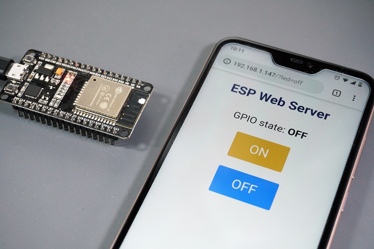
 Before proceeding with this tutorial you should have the ESP32 add-on installed in your Arduino IDE. Follow one of the following tutorials to install the ESP32 on the Arduino IDE, if you haven't already.
Installing the ESP32 Board in Arduino IDE (Windows instructions)
Installing the ESP32 Board in Arduino IDE (Mac and Linux instructions)
We also recommend taking a look at the following resources:
Getting Started with ESP32 Dev Module
ESP32 Pinout Reference: Which GPIO pins should you use?
Before proceeding with this tutorial you should have the ESP32 add-on installed in your Arduino IDE. Follow one of the following tutorials to install the ESP32 on the Arduino IDE, if you haven't already.
Installing the ESP32 Board in Arduino IDE (Windows instructions)
Installing the ESP32 Board in Arduino IDE (Mac and Linux instructions)
We also recommend taking a look at the following resources:
Getting Started with ESP32 Dev Module
ESP32 Pinout Reference: Which GPIO pins should you use?
 (This schematic uses the ESP32 DEVKIT V1 module version with 30 GPIOs if you're using another model, please check the pinout for the board you're using.)

 (This schematic uses the ESP32 DEVKIT V1 module version with 30 GPIOs if you're using another model, please check the pinout for the board you're using.)
 All GPIOs are outputting the same PWM signal. So, all three LEDs increase and decrease the brightness simultaneously, resulting in a synchronized effect.


 Read the voltage from a potentiometer and dim an LED accordingly to the shaft's position of the potentiometer.


 The LED brightness changes when you rotate the potentiometer.

 For demonstration purposes, the web server we'll build controls an ESP32 output, but it can be easily adapted for other purposes like displaying sensor readings.
 The web server you'll build controls an LED connected to the ESP32 GPIO 2. This is the ESP32 on-board LED. You can control any other GPIO;
The web server page shows two buttons: ON and OFF to turn GPIO 2 on and off;
The web server page also shows the current GPIO state.
The following figure shows a simplified diagram to demonstrate how everything works.
The web server you'll build controls an LED connected to the ESP32 GPIO 2. This is the ESP32 on-board LED. You can control any other GPIO;
The web server page shows two buttons: ON and OFF to turn GPIO 2 on and off;
The web server page also shows the current GPIO state.
The following figure shows a simplified diagram to demonstrate how everything works.
 The ESP32 runs a web server code based on the ESPAsyncWebServer library;
The HTML and CSS files are stored on the ESP32 SPIFFS (Serial Peripheral Interface Flash File System);
When you make a request on a specific URL using your browser, the ESP32 responds with the requested files;
When you click the ON button, you are redirected to the root URL followed by
The ESP32 runs a web server code based on the ESPAsyncWebServer library;
The HTML and CSS files are stored on the ESP32 SPIFFS (Serial Peripheral Interface Flash File System);
When you make a request on a specific URL using your browser, the ESP32 responds with the requested files;
When you click the ON button, you are redirected to the root URL followed by 


 If you're using a different operating system, make sure you follow the right guide:
Install uPyCraft IDE Windows PC Instructions
Install uPyCraft IDE Mac OS X Instructions
After installing uPyCraft IDE in your computer, we recommend reading: Getting Started with MicroPython on ESP32 and ESP8266.
If you're using a different operating system, make sure you follow the right guide:
Install uPyCraft IDE Windows PC Instructions
Install uPyCraft IDE Mac OS X Instructions
After installing uPyCraft IDE in your computer, we recommend reading: Getting Started with MicroPython on ESP32 and ESP8266.

 We'll be using this software to flash our ESP based boards with MicroPython firmware as well as to program the boards.
 Follow the next tutorial to flash your ESP boards with the MicroPyhton firmware:
How to flash MicroPython firmware into ESP32/ESP8266
Follow the next tutorial to flash your ESP boards with the MicroPyhton firmware:
How to flash MicroPython firmware into ESP32/ESP8266

 When we upload code to the ESP32 using the Arduino IDE, it just runs we don't have to worry which core executes the code.
There's a function that you can use to identify in which core the code is running:
When we upload code to the ESP32 using the Arduino IDE, it just runs we don't have to worry which core executes the code.
There's a function that you can use to identify in which core the code is running:

 We'll create two tasks running on different cores:
Task1 runs on core 0;
Task2 runs on core 1;
We'll create two tasks running on different cores:
Task1 runs on core 0;
Task2 runs on core 1;
 Upload the next sketch to your ESP32 to blink each LED in a different core:
 As expected Task1 is running on core 0, while Task2 is running on core 1.
In your circuit, one LED should be blinking every 1 second, and the other should be blinking every 700 milliseconds.
As expected Task1 is running on core 0, while Task2 is running on core 1.
In your circuit, one LED should be blinking every 1 second, and the other should be blinking every 700 milliseconds.


 As you can see, it prints the IP address
  In our case, the ESP32 MAC Address is
  In most projects with the ESP32, we connect the ESP32 to a wireless router (see our ESP32 web server tutorial). This way we can access the ESP32 through the local network.
In this situation the router acts as an access point and the ESP32 is set as a station. In this scenario, you need to be connected to your router (local network) to control the ESP32.
In most projects with the ESP32, we connect the ESP32 to a wireless router (see our ESP32 web server tutorial). This way we can access the ESP32 through the local network.
In this situation the router acts as an access point and the ESP32 is set as a station. In this scenario, you need to be connected to your router (local network) to control the ESP32.
 But if you set the ESP32 as an access point (hotspot), you can be connected to the ESP32 using any device with Wi-Fi capabilities without the need to connect to your router.
In simple words, when you set the ESP32 as an access point you create its own Wi-Fi network and nearby Wi-Fi devices (stations) can connect to it (like your smartphone or your computer).
But if you set the ESP32 as an access point (hotspot), you can be connected to the ESP32 using any device with Wi-Fi capabilities without the need to connect to your router.
In simple words, when you set the ESP32 as an access point you create its own Wi-Fi network and nearby Wi-Fi devices (stations) can connect to it (like your smartphone or your computer).
 Here we'll show you how to set the ESP32 as an access point in your web server projects. This way, you don't need to be connected to a router to control your ESP32. Because the ESP32 doesn't connect further to a wired network (like your router), it is called soft-AP (soft Access Point).
 ESP32 development board read ESP32 Development Boards Review and Comparison
2x 5mm LED
2x 330 Ohm resistor
Breadboard
Jumper wires
You can use the preceding links or go directly to MakerAdvisor.com/tools to find all the parts for your projects at the best price!
ESP32 development board read ESP32 Development Boards Review and Comparison
2x 5mm LED
2x 330 Ohm resistor
Breadboard
Jumper wires
You can use the preceding links or go directly to MakerAdvisor.com/tools to find all the parts for your projects at the best price!


 Enter the password you've defined earlier in the code.
 Open your web browser and type the IP address 192.168.4.1. The web server page should load:
 To connect to the access point on your computer, go to the Network and Internet Settings and select the
  Insert the password you've defined earlier.
 And it's done! Now, to access the ESP32 web server page, you just need to type the ESP32 IP address on your browser.

 4) Search for ESP32 and press install button for the
  5) That's it. It should be installed after a few seconds:

 Copy the location from the
  With this example we'll also explore two important concepts: interrupts and timers.
Before proceeding with this tutorial you should have the ESP32 add-on installed in your Arduino IDE. Follow one of the following tutorials to install the ESP32 on the Arduino IDE, if you haven't already.
Installing the ESP32 Board in Arduino IDE (Windows instructions)
Installing the ESP32 Board in Arduino IDE (Mac and Linux instructions)
With this example we'll also explore two important concepts: interrupts and timers.
Before proceeding with this tutorial you should have the ESP32 add-on installed in your Arduino IDE. Follow one of the following tutorials to install the ESP32 on the Arduino IDE, if you haven't already.
Installing the ESP32 Board in Arduino IDE (Windows instructions)
Installing the ESP32 Board in Arduino IDE (Mac and Linux instructions)


 Move your hand in front of the PIR sensor. The LED should turn on, and a message is printed in the Serial Monitor saying MOTION DETECTED!!!. After 10 seconds the LED should turn off.


 There's also another popular method to program ESP32 development boards using the Atom text editor combined with PlatformIO IDE. With this method you can still use the same programming language you use on Arduino IDE.
This next tutorial was tested on a Windows 10 PC and on a Mac OS X computer.
There's also another popular method to program ESP32 development boards using the Atom text editor combined with PlatformIO IDE. With this method you can still use the same programming language you use on Arduino IDE.
This next tutorial was tested on a Windows 10 PC and on a Mac OS X computer.
 After that, open the downloaded installation file and run it. The installation is pretty straightforward. Complete the on-screen instructions to finish the Atom installation.

 After that, press
  Run the next sequence of commands to check the Python and pip version installed:


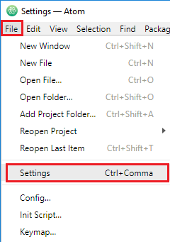 On the left menu, open the
  Search for
  Install the
  Press the
  A new window loads that allows you to create a new project for your board, follow these next steps:
Name your project (example: Blink);
Search for
A new window loads that allows you to create a new project for your board, follow these next steps:
Name your project (example: Blink);
Search for  After the new project is created, you'll see the project folder on the left menu that you can use to navigate through files and folders.
 Open the
  The
The 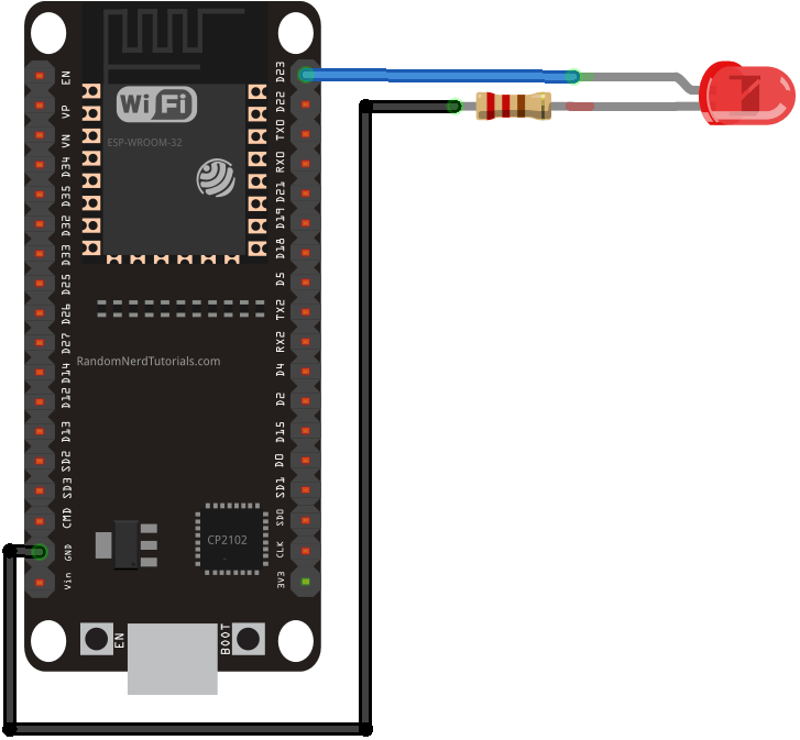 Here's a sketch for testing purposes that blinks the LED:
 Wait a few seconds while the sketch uploads to your board:
 After uploading the sketch, your ESP32 should be blinking the LED attached to GPIO 23 every 1 second.
That's it! The PlatformIO was successfully installed and you can use it to program your ESP32 board.
After uploading the sketch, your ESP32 should be blinking the LED attached to GPIO 23 every 1 second.
That's it! The PlatformIO was successfully installed and you can use it to program your ESP32 board.

 The PlatformIO software should automatically complete your settings. Otherwise, select your ESP32 COM port and its baudrate. Then, press the
  Just like the Arduino IDE Serial Monitor, you have a window that outputs all the Serial.println() commands used in your code:
 As you can see, it's printing the messages: LED on and LED off.

 This modulation technique allows long range communication of small amounts of data (which means a low bandwidth), high immunity to interference, while minimizing power consumption. So, it allows long distance communication with low power requirements.

 Keep in mind that LoRa is not suitable for projects that:
Require high data-rate transmission;
Need very frequent transmissions;
Or are in highly populated networks.
Keep in mind that LoRa is not suitable for projects that:
Require high data-rate transmission;
Need very frequent transmissions;
Or are in highly populated networks.
 Point to point communication
Or build a LoRa network (using LoRaWAN for example)
Point to point communication
Or build a LoRa network (using LoRaWAN for example)
 Unlike Wi-Fi or Bluetooth that only support short distance communication, two LoRa devices with a proper antenna can exchange data over a long distance.
 You can easily configure your ESP32 with a LoRa chip to transmit and receive data reliably at more than 200 meters distance (you can get better results depending on your enviroment and LoRa settings). There are also other LoRa solutions that easily have a range of more than 30Km.
 The LoRaWAN protocol is a Low Power Wide Area Network (LPWAN) specification derived from LoRa technology standardized by the LoRa Alliance. We won't explore LoRaWAN in this tutorial, but for more information you can check the LoRa Alliance and The Things Network websites.
 The later ESP32 has access to Wi-Fi, and it can run a web server that displays the moisture readings.
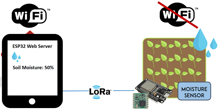 This is just an example that illustrates how you can use the LoRa technology in your ESP32 projects.

 To follow this part you need the following components:
2x ESP32 DOIT DEVKIT V1 Board
2x LoRa Transceiver modules (RFM95)
RFM95 LoRa breakout board (optional)
Jumper wires
Breadboard or stripboard
Alternative:
2x TTGO LoRa32 SX1276 OLED
Instead of using an ESP32 and a separated LoRa transceiver module, there are ESP32 development boards with a LoRa chip and an OLED built-in, which makes wiring much simpler. If you have one of those boards, you can follow: TTGO LoRa32 SX1276 OLED Board: Getting Started with Arduino IDE.
To follow this part you need the following components:
2x ESP32 DOIT DEVKIT V1 Board
2x LoRa Transceiver modules (RFM95)
RFM95 LoRa breakout board (optional)
Jumper wires
Breadboard or stripboard
Alternative:
2x TTGO LoRa32 SX1276 OLED
Instead of using an ESP32 and a separated LoRa transceiver module, there are ESP32 development boards with a LoRa chip and an OLED built-in, which makes wiring much simpler. If you have one of those boards, you can follow: TTGO LoRa32 SX1276 OLED Board: Getting Started with Arduino IDE.


 Before getting your LoRa transceiver module, make sure you check the correct frequency for your location. You can visit the following web page to learn more about RF signals and regulations according to each country. For example, in Portugal we can use a frequency between 863 and 870 MHz or we can use 433MHz. For this project, we'll be using an RFM95 that operates at 868 MHz.
 There are a few options that you can use to access the transceiver pins.
You may solder some wires directly to the transceiver;
Break header pins and solder each one separately;
Or you can buy a breakout board that makes the pins breadboard friendly.
We've soldered a header to the module as shown in the figure below.
There are a few options that you can use to access the transceiver pins.
You may solder some wires directly to the transceiver;
Break header pins and solder each one separately;
Or you can buy a breakout board that makes the pins breadboard friendly.
We've soldered a header to the module as shown in the figure below.
 This way you can access the module's pins with regular jumper wires, or even put some header pins to connect them directly to a stripboard or breadboard.
 You can connect a real antenna, or you can make one yourself by using a conductive wire as shown in the figure below. Some breakout boards come with a special connector to add a proper antenna.
 The wire length depends on the frequency:
868 MHz: 86,3 mm (3.4 inch)
915 MHz: 81,9 mm (3.22 inch)
433 MHz: 173,1 mm (6.8 inch)
For our module we need to use a 86,3 mm wire soldered directly to the transceiver's ANA pin. Note that using a proper antenna will extend the communication range.
The wire length depends on the frequency:
868 MHz: 86,3 mm (3.4 inch)
915 MHz: 81,9 mm (3.22 inch)
433 MHz: 173,1 mm (6.8 inch)
For our module we need to use a 86,3 mm wire soldered directly to the transceiver's ANA pin. Note that using a proper antenna will extend the communication range.


 Congratulations! You've built a LoRa Sender and a LoRa Receiver using the ESP32.
 In this example we're just sending an hello message, but the idea is to replace that text with useful information.

 The ESP32 reads temperature using the DS18B20 temperature sensor.
After getting the temperature, it makes a request to an NTP (Network Time Protocol) server to get date and time. So, the ESP32 needs a Wi-Fi connection.
The data (temperature and timestamp) are logged to a microSD card. To log data to the microSD card we're using a microSD card module.
After completing these previous tasks, the ESP32 sleeps for 10 minutes.
The ESP32 wakes up and repeats the process.
The ESP32 reads temperature using the DS18B20 temperature sensor.
After getting the temperature, it makes a request to an NTP (Network Time Protocol) server to get date and time. So, the ESP32 needs a Wi-Fi connection.
The data (temperature and timestamp) are logged to a microSD card. To log data to the microSD card we're using a microSD card module.
After completing these previous tasks, the ESP32 sleeps for 10 minutes.
The ESP32 wakes up and repeats the process.
 ESP32 DOIT DEVKIT V1 Board read ESP32 Development Boards Review and Comparison
MicroSD card module
MicroSD card
DS18B20 temperature sensor
10k Ohm resistor
Jumper wires
Breadboard
You can use the preceding links or go directly to MakerAdvisor.com/tools to find all the parts for your projects at the best price!
ESP32 DOIT DEVKIT V1 Board read ESP32 Development Boards Review and Comparison
MicroSD card module
MicroSD card
DS18B20 temperature sensor
10k Ohm resistor
Jumper wires
Breadboard
You can use the preceding links or go directly to MakerAdvisor.com/tools to find all the parts for your projects at the best price!


 You can copy the file content to a spreadsheet on Google Sheets for example, and then split the data by commas. To split data by commas, select the column where you have your data, then go to

 The Node-RED application publishes messages (
 Raspberry Pi read Best Raspberry Pi 3 Starter Kits
ESP32 DOIT DEVKIT V1 Board read ESP32 Development Boards Review and Comparison
BME280 sensor module
1x 5mm LED
1x 220 Ohm resistor
Breadboard
Jumper wires
You can use the preceding links or go directly to MakerAdvisor.com/tools to find all the parts for your projects at the best price!
Raspberry Pi read Best Raspberry Pi 3 Starter Kits
ESP32 DOIT DEVKIT V1 Board read ESP32 Development Boards Review and Comparison
BME280 sensor module
1x 5mm LED
1x 220 Ohm resistor
Breadboard
Jumper wires
You can use the preceding links or go directly to MakerAdvisor.com/tools to find all the parts for your projects at the best price!
 The sensor can communicate using either SPI or I2C communication protocols (there are modules of this sensor that just communicate with I2C, these just come with four pins).
To use SPI communication protocol, use the following pins:
SCK this is the SPI Clock pin
SDO MISO
SDI MOSI
CS Chip Select
To use I2C communication protocol, the sensor uses the following pins:
SCK SCL pin
SDI SDA pin
The sensor can communicate using either SPI or I2C communication protocols (there are modules of this sensor that just communicate with I2C, these just come with four pins).
To use SPI communication protocol, use the following pins:
SCK this is the SPI Clock pin
SDO MISO
SDI MOSI
CS Chip Select
To use I2C communication protocol, the sensor uses the following pins:
SCK SCL pin
SDI SDA pin
 Here's how your circuit should look:


 Then, paste the code provided and click
  The following nodes should load:
 After making any changes, click the


 ESP32 DOIT DEVKIT V1 Board read ESP32 Development Boards Review and Comparison
DC motor
L298N motor driver
Power source: 4x 1.5 AA batteries or Bench power supply
2x 100nF ceramic capacitors (optional)
1x SPDT slide switch (optional)
Jumper wires
You can use the preceding links or go directly to MakerAdvisor.com/tools to find all the parts for your projects at the best price!
ESP32 DOIT DEVKIT V1 Board read ESP32 Development Boards Review and Comparison
DC motor
L298N motor driver
Power source: 4x 1.5 AA batteries or Bench power supply
2x 100nF ceramic capacitors (optional)
1x SPDT slide switch (optional)
Jumper wires
You can use the preceding links or go directly to MakerAdvisor.com/tools to find all the parts for your projects at the best price!

 The motor driver has a two terminal block in each side for each motor. OUT1 and OUT2 at the left and OUT3 and OUT4 at the right.


 But if you're using more than one servo or other type, you'll probably need to power up your servos using an external power supply.
 If you're using a small servo like the S0009, you need to connect:
GND -> ESP32 GND pin;
Power -> ESP32 VIN pin;
Signal -> GPIO 13 (or any PWM pin).
If you're using a small servo like the S0009, you need to connect:
GND -> ESP32 GND pin;
Power -> ESP32 VIN pin;
Signal -> GPIO 13 (or any PWM pin).

 To control the motor you can simply use the PWM capabilities of the ESP32 by sending a 50Hz signal with the appropriate pulse width. Or you can use a library to make this task much simpler.


 Press the ESP32 Enable button to restart the board, and copy the ESP32 IP address that shows up on the Serial Monitor.
 Open your browser, paste the ESP IP address, and you should see the web page you've created previously. Move the slider to control the servo motor.
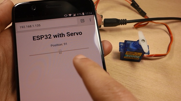 In the Serial Monitor, you can also see the HTTP requests you're sending to the ESP32 when you move the slider.
 Experiment with your web server for a while to see if it's working properly.

 First, the ESP connects to your Wi-Fi network;
Then, the BME280 takes the temperature, humidity, and pressure readings;
Your ESP32 or ESP8266 communicates with the IFTTT Webhooks service that publishes the readings to a spreadsheet on Google Sheets that is saved in your Google Drive's folder;
After publishing the readings, the ESP goes into deep sleep mode for 30 minutes;
After 30 minutes the ESP wakes up;
After waking up, the ESP connects to Wi-Fi, and the process repeats.
First, the ESP connects to your Wi-Fi network;
Then, the BME280 takes the temperature, humidity, and pressure readings;
Your ESP32 or ESP8266 communicates with the IFTTT Webhooks service that publishes the readings to a spreadsheet on Google Sheets that is saved in your Google Drive's folder;
After publishing the readings, the ESP goes into deep sleep mode for 30 minutes;
After 30 minutes the ESP wakes up;
After waking up, the ESP connects to Wi-Fi, and the process repeats.


 Continue reading this post to see how to integrate the IFTTT Google Sheets service with your ESP32 or ESP8266.


 The ESP32 chip has a built-in clock, so the readings are very accurate and it publishes to the spreadsheet every 30 minutes. On the other hand, the ESP8266 publishes new readings approximately every 28 to 29 minutes.

 I've designed the shield to be a compact weather station. The PCB has a lot of features so that it can suit a lot of different projects for different applications. In fact, I didn't use all the PCB features in this project.
Additionally, this shield can also be used as a learning shield as it comes with some of the most used components when starting to learn how to program the ESP32.
I've designed the shield to be a compact weather station. The PCB has a lot of features so that it can suit a lot of different projects for different applications. In fact, I didn't use all the PCB features in this project.
Additionally, this shield can also be used as a learning shield as it comes with some of the most used components when starting to learn how to program the ESP32.
 The shield allows you to control:
2x SMD LEDs
1x Pushbutton
1x Trimpot
1x DHT22 temperature and humidity sensor
1x BMP180 barometric sensor
1x Light dependent resistor
1x MicroSD card module
2x Terminal blocks that give you access to 3 GPIOs to connect other components
The microSD card module is a very interesting addition to the shield: it can be used to store readings if you want to build a data logger, or it can store an HTML file to serve a web page as we'll do in this project. I think this is a better and easier way to build a web server that requires more complex web pages.
The shield allows you to control:
2x SMD LEDs
1x Pushbutton
1x Trimpot
1x DHT22 temperature and humidity sensor
1x BMP180 barometric sensor
1x Light dependent resistor
1x MicroSD card module
2x Terminal blocks that give you access to 3 GPIOs to connect other components
The microSD card module is a very interesting addition to the shield: it can be used to store readings if you want to build a data logger, or it can store an HTML file to serve a web page as we'll do in this project. I think this is a better and easier way to build a web server that requires more complex web pages.


 3. You'll see a success message at the bottom. Then, you can use the Gerber Viewer link at the bottom right corner to check if everything went as expected. You can view the top and bottom of the PCB. You can view or hide the solder-mask, silkscreen, copper, etc.
 With the default settings, you can order 10 PCBs for just $2. However, if you want to select other settings like a different PCB Color it will cost you a few more dollars.
When, you're happy with your order. Click the
With the default settings, you can order 10 PCBs for just $2. However, if you want to select other settings like a different PCB Color it will cost you a few more dollars.
When, you're happy with your order. Click the  My PCBs took 1 day to be manufactured and they arrived in 5 business days using DHL delivery option.
 Taking a closer look at the PCBs, I must say that I'm really impressed with the quality. I don't think you can get a better PCB service for this price.

 Here's a list of all the components you need to solder on the PCB:
2x SMD LEDs
2x 330 Ohm SMD resistors
1x 10k Ohm SMD resistor
1x 4.7k Ohm SMD resistor
1x Trimpot (10k)
1x Pushbutton
1x SD card module
1x BMP180 barometric sensor
1x DHT22 temperature and humidity sensor
2x Screw terminal blocks
Female pin header socket
ESP32 DOIT DEVKIT V1 Board (version with 30 GPIOs) you can get this board from Banggood, or from eBay
The following figure shows how the PCB looks like after soldering all the components.
Here's a list of all the components you need to solder on the PCB:
2x SMD LEDs
2x 330 Ohm SMD resistors
1x 10k Ohm SMD resistor
1x 4.7k Ohm SMD resistor
1x Trimpot (10k)
1x Pushbutton
1x SD card module
1x BMP180 barometric sensor
1x DHT22 temperature and humidity sensor
2x Screw terminal blocks
Female pin header socket
ESP32 DOIT DEVKIT V1 Board (version with 30 GPIOs) you can get this board from Banggood, or from eBay
The following figure shows how the PCB looks like after soldering all the components.

 Now, everything should be ready.
 By the end of the project, you have your own ESP32 weather station web server, and all the hardware is well compacted on a PCB.
Open your browser, type the IP address and you should see a table with the latest sensor readings. The web server displays the DHT22, BMP180, potentiometer and LDR readings. The readings are updated every 10 seconds without the need to refresh the web page.
By the end of the project, you have your own ESP32 weather station web server, and all the hardware is well compacted on a PCB.
Open your browser, type the IP address and you should see a table with the latest sensor readings. The web server displays the DHT22, BMP180, potentiometer and LDR readings. The readings are updated every 10 seconds without the need to refresh the web page.
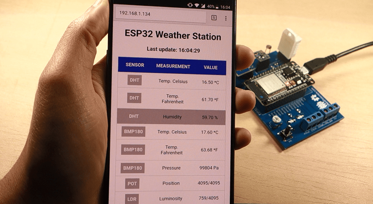 To update the readings without refreshing the web page, we use AJAX. As you can read here, AJAX is a developer's dream, because it can update the web page without reloading the page, request and receive data from a server, after the page has loaded, and send data to a server in the background.
